EP1559951B1 - Feu de véhicule et procédé de montage pour feu de véhicule - Google Patents
Feu de véhicule et procédé de montage pour feu de véhicule Download PDFInfo
- Publication number
- EP1559951B1 EP1559951B1 EP05100287A EP05100287A EP1559951B1 EP 1559951 B1 EP1559951 B1 EP 1559951B1 EP 05100287 A EP05100287 A EP 05100287A EP 05100287 A EP05100287 A EP 05100287A EP 1559951 B1 EP1559951 B1 EP 1559951B1
- Authority
- EP
- European Patent Office
- Prior art keywords
- section
- dome
- headlamp
- cross
- oblong opening
- Prior art date
- Legal status (The legal status is an assumption and is not a legal conclusion. Google has not performed a legal analysis and makes no representation as to the accuracy of the status listed.)
- Expired - Lifetime
Links
- 238000000034 method Methods 0.000 title claims abstract description 10
- 230000007704 transition Effects 0.000 description 7
- 238000006073 displacement reaction Methods 0.000 description 3
- 238000001746 injection moulding Methods 0.000 description 2
- 238000003780 insertion Methods 0.000 description 2
- 230000037431 insertion Effects 0.000 description 2
- 239000000463 material Substances 0.000 description 2
- 230000003534 oscillatory effect Effects 0.000 description 2
- 210000000746 body region Anatomy 0.000 description 1
- 238000010276 construction Methods 0.000 description 1
- 230000000694 effects Effects 0.000 description 1
- 238000009434 installation Methods 0.000 description 1
- 230000002265 prevention Effects 0.000 description 1
Images


Classifications
-
- B—PERFORMING OPERATIONS; TRANSPORTING
- B60—VEHICLES IN GENERAL
- B60Q—ARRANGEMENT OF SIGNALLING OR LIGHTING DEVICES, THE MOUNTING OR SUPPORTING THEREOF OR CIRCUITS THEREFOR, FOR VEHICLES IN GENERAL
- B60Q1/00—Arrangement of optical signalling or lighting devices, the mounting or supporting thereof or circuits therefor
- B60Q1/26—Arrangement of optical signalling or lighting devices, the mounting or supporting thereof or circuits therefor the devices being primarily intended to indicate the vehicle, or parts thereof, or to give signals, to other traffic
- B60Q1/2615—Arrangement of optical signalling or lighting devices, the mounting or supporting thereof or circuits therefor the devices being primarily intended to indicate the vehicle, or parts thereof, or to give signals, to other traffic mounted on the vehicle body, e.g. with magnets
Definitions
- the invention relates to a vehicle lamp with a housing according to the preamble of patent claim 1.
- a vehicle lamp which consists of a housing, a printed circuit board arranged in the housing with an LED contacted thereon as the light source and a housing closing the lens.
- the housing has in its rear region a projecting from the housing dome, through which the electrical contact of the vehicle lamp is passed.
- at least two bores for carrying out fastening screws are introduced into the housing.
- the vehicle body In order to mount the light on the vehicle body or on a holding element arranged on the vehicle body for this purpose, the vehicle body must have an opening for the dome and, in addition to the bores of the housing, suitable bores.
- the vehicle lamp is placed on the vehicle body or the holding element and the fastening screws are pushed through the holes of the housing and the vehicle body or the holding element. Then in a second assembly step in each case a threaded nut must be screwed onto the mounting screws in order to screw them in a third assembly step by means of suitable tools and to secure the vehicle lamp.
- a disadvantage of the known vehicle lamp and the associated method for mounting is that the housing must have additional holes and the vehicle body or the retaining element according to cursing holes for the mounting screws. Furthermore, it is disadvantageous that must be mounted during assembly both from the front and from the back and that for the assembly tool is needed.
- a vehicle lamp with a housing and a projecting from the housing dome known.
- the dome protrudes from a rear side of the housing and allows a fixing of the housing to a receiving area of the vehicle body.
- a disadvantage of the known vehicle lamp is that a further dome for locking the housing must be provided on the vehicle body, which engages in a corresponding opening after the housing has been rotated after insertion of the dome in the receiving area.
- a disadvantage of the known vehicle lamp is further that for disassembling the same a screwdriver must be inserted into a disassembly slot of the lamp to allow lifting of the vehicle lamp and a subsequent unscrewing against the installation twisting.
- a vehicle lamp with a housing and a back-projecting dome known.
- the vehicle lamp is inserted in the region of a circular collar laterally into a slot of a locking receptacle, so that the housing of the vehicle lamp is latchingly held in the ⁇ -shaped locking receptacle.
- the object of the invention is to develop a vehicle lamp according to the preamble of claim 1, and the method for mounting such a vehicle lamp so that it is simple and inexpensive to produce and in addition quickly and without mounting tools on a vehicle body or arranged on the vehicle body holding element can be mounted.
- the invention has the features of claim 1.
- the vehicle lamp by means of projecting from the rear region of the housing dome in the receiving area of the vehicle body or the arranged on the vehicle body holding element can be fixed, the vehicle lamp is simple and inexpensive to produce, since it does not have to have additional areas in which mounting screws or other fasteners can be arranged, which saves material and the vehicle additional space.
- the arranged on the vehicle lamp dome thus fulfills the one task that it passes through the electrical contact of the vehicle lamp and on the other hand the task that the vehicle lamp is fixed by means of the dome.
- the embodiment according to the invention is characterized in that the projecting dome has at least one collar-shaped region, that the receiving region has at least one slot-shaped opening which is formed such that at least a portion of the slot-shaped openings in the width cross-section greater than the cross-section of the collar-shaped portion of the dome and at least one further region of the slot-shaped opening in the width cross-section is smaller than the cross-section of the collar-shaped region of the dome and wherein the dome arranged in a rear region of the vehicle lamp is displaceable in the slot-shaped opening and thereby fixable.
- Forming a dome with a collar-shaped area is easy to implement in terms of injection molding in the case of the housings customarily produced in the plastic injection molding process.
- the slot-shaped opening with the different width cross-sections is easy to produce, since it can be stamped for example in the vehicle body.
- the slot-like opening is formed similar to a keyhole and thus allows the insertion and the displacement of the dome in the opening.
- the vehicle lamp in the fixed position in the receiving area permanently safe and rattle-free, according to the invention has a transition region between the at least two different width cross-sectional dimensions of the slot-shaped opening resilient latching elements. Particularly safe and rattle-free, the vehicle lamp is held when the width cross-section of the resilient latching element in the normal position is less than the cross section of the dome.
- the slot-shaped opening has at least two areas whose width cross section is larger than the cross section of the collar-shaped area of the dome list.
- a movement of the vehicle lamp in the fixed position in the axial direction of the dome is prevented in an advantageous development of the vehicle lamp according to the invention that the distance between the rear wall of the housing of the vehicle lamp and pointing to the housing edge of the arranged on the cathedral collar-shaped area only slightly larger is, as the thickness of the slot-shaped opening surrounding body portion or retaining element.
- the body region surrounding the slot-shaped opening or the retaining element surrounded the slot-shaped opening has a circumferential ridge, which corresponds to the outer contour of the vehicle lamp and includes these in the installed state.
- the circumferential web has at least one interruption in an advantageous development, so that the vehicle lamp is pressed slightly over the web by means of a tool and then displaced in the slot-shaped opening can.
- the vehicle lamp may have resilient regions in the outer region of its contour.
- the vehicle lamp is protected in the fixed position against rotation about the longitudinal axis of the dome and thus ensures the desired light distribution, which surrounds the slot-shaped opening body portion or the slot-shaped opening surrounding retaining element at least one further guidance region for the vehicle lamp.
- the method of assembly is advantageously designed such that in a first assembly step, the dome with the collar-shaped region arranged thereon is pushed through the region of the slot-shaped opening whose width cross section is greater than the cross section of the collar-shaped region of the dome and that in a second assembly step Vehicle lamp is displaced in accordance with the longitudinal orientation of the slot-shaped opening in the direction of the region of the slot-shaped opening whose width cross section is smaller than the cross section of the collar-shaped portion of the dome.
- the vehicle lamp is kept permanently secure and rattle-free in the receiving area, since the method for mounting is additionally designed such that the arranged in a transition region between the at least two different width cross-sectional dimensions of the slot-shaped opening resilient locking elements during the second assembly step through the dome only to the longitudinal edges the slot-shaped opening are pressed and, as soon as the dome is moved into the region of the slot-shaped opening whose width cross section is smaller than the cross section of the collar-shaped portion of the dome, spring back to its normal position.
- the dome is held against the force of the resilient locking elements in the region of the slot-shaped opening whose width cross section is smaller than the cross section of the collar-shaped portion of the dome.
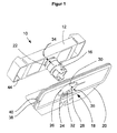
- FIG. 1 shows in a perspective view from below a vehicle lamp (10) according to the invention in the unassembled state, and a holding element (20) having a receiving area (18) for the vehicle lamp (10), wherein the holding element (20) on a vehicle body, not shown is arranged.
- a holding element (20) having a receiving area (18) for the vehicle lamp (10), wherein the holding element (20) on a vehicle body, not shown is arranged.
- the dome (16) has, in addition to holding and locking elements for the contact arrangement, not shown, a collar-shaped region (22).
- the first region (26) of the slot-shaped opening (24) has a width cross section which is greater than the cross section of the collar-shaped region (22) of the dome (16).
- resilient detent elements (32) are arranged, which are pressed during the pushing movement of the vehicle lamp (10) through the dome (16) to the longitudinal edges of the slot-shaped opening (24) and as soon as the dome ( 16) in the second region (28), spring back to its normal position.
- This locking element (32) cause the dome (16) is securely and permanently fixed in the second area (28) and thus prevent rattling of the vehicle lamp (10) due to unwanted oscillatory movements in the longitudinal extent of the slot-shaped opening (24).
- the holding element (20) in addition to the locking elements (32) has a circumferential ridge (38) which is connected to the outer contour of the vehicle lamp (10) corresponds and encloses this in the installed state.
- the vehicle lamp (10) now, it has to be pushed over the web (38) at least on a side surface lying in the direction of the longitudinal extent of the slot-shaped opening (24).
- the housing (12) on specially designed resilient areas (44) which are pressed during assembly in the direction opposite to the holding element (20) and as soon as the vehicle lamp (10) is mounted, spring back to its desired position.
- the web (38) has at least one interruption (40) through which the resilient region (44) of the housing (12) can be engaged behind by means of an auxiliary tool, via the web (38) is lifted and the vehicle lamp (10) in the slot-shaped opening (24) of the second region (28) in the first region (26) can be moved ,
- the vehicle lamp (10) is securely and permanently fixed to the holding element (20).
- FIG. 2 shows the in FIG. 1 illustrated vehicle lamp (10) in a perspective view from above.
- the vehicle lamp (10) consists of a housing (12) which is covered by a lens (14).
- the further construction of the vehicle lamp (10), the holding element (20), the method of assembly and the method for disassembly is in the description of the figures FIG. 1 has been explained sufficiently, so that it needs no rest here.
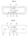
- FIGS. 3a to 3d show different design variants of the receiving area (18).
- FIG. 3a is the receiving area (18) similar to that in FIG. 1 and FIG. 2 formed receiving area (18).
- the latching elements (32) arranged in the transition area (30) between the first area (26) and the second area (28) exert their resilient effect via notches in the adjacent, full-surface area Achieve material area.
- the latching elements (32) arranged in the transition region (30) between the first region (26) and the second region (28) are formed in a sawtooth shape counter to the dismantling direction of the vehicle lamp so as to prevent disassembly of a vehicle lamp once mounted.
- This measure can serve, for example, for theft prevention.
- the holding element according to FIG. 3b Guide portions (42) engage in the integrally formed on the rear portion of the vehicle lamp mandrels to prevent rotation of the vehicle lamp.
- the receiving area (18) has a slot-shaped opening (24) with two first areas (26), so that the vehicle lamp can be mounted from two sides.
- a second region (28) is formed in the central region of the slot-shaped opening (24).
- latching elements (32) arranged on the right and left in the transition region (30).
- 3d figure shows a receiving area (18) for vehicle lights, which has two spaced-apart, projecting from the rear portion of the housing dome.
- the two domes are pushed through the first two areas (26) of the slot-shaped opening (24) and then the vehicle lamp according to the longitudinal extension of the slot-shaped opening (24) in the two second regions (28) displaced and thereby fixed.
Landscapes
- Engineering & Computer Science (AREA)
- Mechanical Engineering (AREA)
- Lighting Device Outwards From Vehicle And Optical Signal (AREA)
- Non-Portable Lighting Devices Or Systems Thereof (AREA)
- Automobile Manufacture Line, Endless Track Vehicle, Trailer (AREA)
Claims (9)
- Feu de véhicule (10) avec un boîtier (12), une glace (14) fermant le boîtier (12), au moins une source lumineuse disposée dans le feu du véhicule (10), au moins un dôme (16) faisant saillie d'une zone arrière du boîtier (12) et permettant le passage de la connexion électrique du feu du véhicule (10) et au moins une zone de logement (18) pour le feu du véhicule (10) sur une carrosserie de véhicule ou sur un élément de maintien (20) fixé pour cela à la carrosserie de véhicule,
le feu de véhicule (10) pouvant être fixé dans la zone de logement (18) de la carrosserie de véhicule ou l'élément de maintien (20) disposé pour cela sur la carrosserie de véhicule par l'intermédiaire du dôme (16) faisant saillie de la zone arrière du boîtier (12),
caractérisé en ce que
le dôme saillant (16) présente au moins une zone en forme de collerette (22),
la zone de logement (18) présente au moins une ouverture en forme de trou oblong (24) qui est conçue de façon telle qu'au moins une zone (26) de l'ouverture en forme de trou oblong (24) est, dans la section en largeur, plus grande que la section de la zone en forme de collerette (22) du dôme (16) et au moins une autre zone (28) de l'ouverture en forme de trou oblong (24) est, dans la section en largeur, plus petite que la section de la zone en forme de collerette (22) du dôme (16)
et le dôme (16) disposé dans une zone arrière du feu de véhicule (10) pouvant être déplacé dans l'ouverture en forme de trou oblong (24) et être fixé par le fait qu'une zone de transition (30) entre les zones (26, 28) - ayant des dimensions de section en largeur différentes - de l'ouverture en forme de trou oblong (24) présente des éléments d'encliquetage élastiques (32). - Feu de véhicule selon la revendication 1, caractérisé en ce que l'ouverture en forme de trou oblong (24) présente au moins deux zones (26) dont la section en largeur est plus grande que la section de la zone en forme de collerette (22) du dôme (16).
- Feu de véhicule selon la revendication 1 ou 2. caractérisé en ce que l'ouverture en forme de trou oblong (24) présente le même nombre de zones (26, 28) dont la section en largeur est plus grande que la section de la zone en forme de collerette (22) du dôme (16) et dont la section en largeur est plus petite que la section de la zone en forme de collerette (22) du dôme (16).
- Feu de véhicule selon l'une des revendications 1 à 3, caractérisé en ce que la section en largeur des éléments d'encliquetage élastiques (32) est, en position normale, plus petite que la section du dôme (16).
- Feu de véhicule selon l'une dés revendications 1 à 4, caractérisé en ce que la distance (34) entre la paroi arrière du boîtier (12) du feu de véhicule (10) et le bord, faisant face au boîtier (12), de la zone en forme de collerette (22) disposée sur le dôme (16) n'est que légèrement plus grande que l'épaisseur (36) de la zone de carrosserie ou de l'élément de maintien (20) entourant l'ouverture en forme de trou oblong (24).
- Feu de véhicule selon l'une des revendications 1 à 5, caractérisé en ce que la zone de carrosserie entourant l'ouverture en forme de trou oblong (24) ou l'élément de maintien (20) entourant l'ouverture en forme de trou oblong (24) présente une nervure périphérique (38) qui correspond au contour extérieur du feu de véhicule (10) et englobe celui-ci à l'état monté.
- Feu de véhicule selon la revendication 6. caractérisé en ce que la nervure périphérique (38) présente au moins une interruption (40).
- Feu de véhicule selon l'une des revendications 1 à 7, caractérisé en ce que la zone de carrosserie entourant l'ouverture en forme de trou oblong (24) ou l'élément de maintien (20) entourant l'ouverture en forme de trou oblong (24) présente au moins une autre zone de guidage (42) pour le feu de véhicule (10).
- Procédé de montage d'un feu de véhicule (10) conçu conformément aux revendications précédentes, dans lequel le feu de véhicule (10) peut être fixé par l'intermédiaire d'un mouvement relatif entre le dôme (16) faisant saillie de la zone arrière du boîtier (12) et la zone de logement (18) de la carrosserie de véhicule ou de l'élément de maintien (20) disposé pour cela sur la carrosserie de véhicule,
caractérisé en ce que
dans une première étape de montage, le dôme (16) avec la zone en forme de collerette (22) disposée dessus est passé à travers la zone (26) de l'ouverture en forme de trou oblong (24) dont la section en largeur est plus grande que la section de la zone en forme de collerette (22) du dôme (16), et
dans une deuxième étape de montage, le feu de véhicule (10) est, d'après l'orientation longitudinale de l'ouverture en forme de trou oblong (24), déplacé en direction de la zone (28) de l'ouverture en forme de trou oblong (24) dont la section en largeur est plus petite que la section de la zone en forme de collerette (22) du dôme (16), et
les éléments d'encliquetage élastiques (32) disposés dans la zone de transition (30) entre les au moins deux dimensions de section en largeur différentes de l'ouverture en forme de trou oblong (24) sont dans un premier temps poussés par le dôme (16) en direction des arêtes longitudinales de l'ouverture en forme de trou oblong (24) et, dès que le dôme (16) est déplacé dans la zone (28) de l'ouverture en forme de trou oblong (24) dont la section en largeur est plus petite que la section de la zone en forme de collerette (22) du dôme (16), reviennent élastiquement dans leur position normale.
Applications Claiming Priority (2)
| Application Number | Priority Date | Filing Date | Title |
|---|---|---|---|
| DE102004004129A DE102004004129A1 (de) | 2004-01-28 | 2004-01-28 | Fahrzeugleuchte und Verfahren zur Montage der Fahrzeugleuchte |
| DE102004004129 | 2004-01-28 |
Publications (3)
| Publication Number | Publication Date |
|---|---|
| EP1559951A2 EP1559951A2 (fr) | 2005-08-03 |
| EP1559951A3 EP1559951A3 (fr) | 2006-10-25 |
| EP1559951B1 true EP1559951B1 (fr) | 2008-05-07 |
Family
ID=34638763
Family Applications (1)
| Application Number | Title | Priority Date | Filing Date |
|---|---|---|---|
| EP05100287A Expired - Lifetime EP1559951B1 (fr) | 2004-01-28 | 2005-01-19 | Feu de véhicule et procédé de montage pour feu de véhicule |
Country Status (3)
| Country | Link |
|---|---|
| EP (1) | EP1559951B1 (fr) |
| AT (1) | ATE394633T1 (fr) |
| DE (2) | DE102004004129A1 (fr) |
Families Citing this family (6)
| Publication number | Priority date | Publication date | Assignee | Title |
|---|---|---|---|---|
| DE102005001103A1 (de) * | 2005-01-08 | 2006-07-20 | Hella Kgaa Hueck & Co. | Fahrzeugleuchte |
| FR2925416B1 (fr) * | 2007-12-19 | 2010-01-22 | Peugeot Citroen Automobiles Sa | Bloc optique a fixer sur une structure de vehicule |
| DE102010026218A1 (de) * | 2010-07-06 | 2012-01-12 | Gm Global Technology Operations Llc (N.D.Ges.D. Staates Delaware) | Befestigungsmittel |
| DE102012024275A1 (de) * | 2012-12-12 | 2014-06-26 | GM Global Technology Operations LLC (n. d. Gesetzen des Staates Delaware) | Befestigungsvorrichtung zum Befestigen von mechanischen, elektrischen und/oder elektronischen Modulen |
| DE102013102835B4 (de) * | 2013-03-20 | 2022-12-29 | HELLA GmbH & Co. KGaA | Beleuchtungsvorrichtung |
| CN110230798B (zh) * | 2019-03-28 | 2024-05-14 | 常州星宇车灯股份有限公司 | 防拆卸车灯和具有其的车辆 |
Family Cites Families (3)
| Publication number | Priority date | Publication date | Assignee | Title |
|---|---|---|---|---|
| DD262633A1 (de) * | 1987-06-12 | 1988-12-07 | Ruhla Fahrzeugelektrik | Leuchte fuer fahrzeuge, insbesondere kennzeichenleuchte fuer kraftfahrzeuge |
| FR2662981B1 (fr) * | 1990-06-08 | 1992-07-31 | Valeo Vision | Dispositif et procede pour le montage automatique d'un equipement sur support, et plus particulierement d'un dispositif d'eclairage et/ou de signalisation sur un vehicule automobile. |
| DE20302651U1 (de) * | 2003-02-18 | 2003-06-12 | ASPÖCK Systems Fahrzeugelektrik Ges.m.b.H. & Co KG, Peuerbach | Punktaußenleuchte für Fahrzeuge |
-
2004
- 2004-01-28 DE DE102004004129A patent/DE102004004129A1/de not_active Withdrawn
-
2005
- 2005-01-19 AT AT05100287T patent/ATE394633T1/de not_active IP Right Cessation
- 2005-01-19 DE DE502005003931T patent/DE502005003931D1/de not_active Expired - Lifetime
- 2005-01-19 EP EP05100287A patent/EP1559951B1/fr not_active Expired - Lifetime
Also Published As
| Publication number | Publication date |
|---|---|
| DE102004004129A1 (de) | 2005-09-08 |
| DE502005003931D1 (de) | 2008-06-19 |
| EP1559951A2 (fr) | 2005-08-03 |
| EP1559951A3 (fr) | 2006-10-25 |
| ATE394633T1 (de) | 2008-05-15 |
Similar Documents
| Publication | Publication Date | Title |
|---|---|---|
| EP2655902B1 (fr) | Écrou de cage pourvu d'un dispositif de retenue | |
| EP1979634B1 (fr) | Unité de montage destinée à un anneau de fixation d'une boucle de ceinture | |
| EP1810896B1 (fr) | Module avec un capteur de pluie et une agrafe de fixation pour le capteur de pluie. | |
| DE4413635C2 (de) | Befestigungsvorrichtung für eine Scheibenwischeranlage | |
| DE10304278B4 (de) | Struktur zur Befestigung einer Anzeigeeinheit an einer Instrumentenkonsole eines Automobils | |
| DE102017209492A1 (de) | Halterung zur Befestigung eines Sensors, insbesondere Radarsensors, an einem Fahrzeug und ein System aus einer Halterung und dem Sensor | |
| EP0790153B1 (fr) | Dispositif de fixation d'un module de sac de sécurité gonflable | |
| DE102017210291A1 (de) | Halterung zur Befestigung eines Sensors, insbesondere Radarsensors, an einem Fahrzeug und ein System aus einer Halterung und dem Sensor | |
| WO2007131830A1 (fr) | Dispositif et procédé pour fixer un moteur d'essuie-glace sur une tringlerie d'essuie-glace | |
| EP1559951B1 (fr) | Feu de véhicule et procédé de montage pour feu de véhicule | |
| EP3934022B1 (fr) | Antenne de toit | |
| DE3210164C2 (de) | Vorrichtung zum Befestigen eines Lüfters in einer Gehäusewand eines elektrischen Gerätes | |
| DE3921173C2 (fr) | ||
| WO2005051695A1 (fr) | Support d'unite comportant un systeme de fixation de serrure integre destine a une portiere de vehicule | |
| EP0609534B1 (fr) | Dispositif pour fixer des pièces, en particulier des pièces de véhicules à moteur | |
| EP0092665B1 (fr) | Dispositif de fixation pour le bras d'un rétroviseur extérieur de véhicule utilitaire | |
| DE102016218271A1 (de) | Manteleinheit für eine verstellbare Lenksäule eines Kraftfahrzeugs | |
| DE69806445T2 (de) | Vorrichtung zur vorübergehenden Befestigung einer Beleuchtungs- oder Signaleinrichtung auf der Karosserie eines Kraftfahrzeuges | |
| DE102006059096B4 (de) | Baugruppe zur fahrzeugseitigen Befestigung eines Gurtschlosses | |
| DE10334629B3 (de) | Schaltungsmodul und Verfahren zu dessen Herstellung | |
| EP1375275A2 (fr) | Unité d'entraínement avec un élément d' arrêt | |
| EP0412418A2 (fr) | Bouton de demande d'arrêt | |
| EP1371530B1 (fr) | Dispositif de fixation | |
| DE102016107858B4 (de) | Heckblendenanordnung eines Kraftfahrzeugs | |
| EP0063294B1 (fr) | Dispositif de fixation, en particulier pour accoudoir ou poignées à la paroi intérieure de carosserie pour véhicules |
Legal Events
| Date | Code | Title | Description |
|---|---|---|---|
| PUAI | Public reference made under article 153(3) epc to a published international application that has entered the european phase |
Free format text: ORIGINAL CODE: 0009012 |
|
| AK | Designated contracting states |
Kind code of ref document: A2 Designated state(s): AT BE BG CH CY CZ DE DK EE ES FI FR GB GR HU IE IS IT LI LT LU MC NL PL PT RO SE SI SK TR |
|
| AX | Request for extension of the european patent |
Extension state: AL BA HR LV MK YU |
|
| PUAL | Search report despatched |
Free format text: ORIGINAL CODE: 0009013 |
|
| AK | Designated contracting states |
Kind code of ref document: A3 Designated state(s): AT BE BG CH CY CZ DE DK EE ES FI FR GB GR HU IE IS IT LI LT LU MC NL PL PT RO SE SI SK TR |
|
| AX | Request for extension of the european patent |
Extension state: AL BA HR LV MK YU |
|
| 17P | Request for examination filed |
Effective date: 20070327 |
|
| 17Q | First examination report despatched |
Effective date: 20070430 |
|
| AKX | Designation fees paid |
Designated state(s): AT BE BG CH CY CZ DE DK EE ES FI FR GB GR HU IE IS IT LI LT LU MC NL PL PT RO SE SI SK TR |
|
| GRAC | Information related to communication of intention to grant a patent modified |
Free format text: ORIGINAL CODE: EPIDOSCIGR1 |
|
| GRAP | Despatch of communication of intention to grant a patent |
Free format text: ORIGINAL CODE: EPIDOSNIGR1 |
|
| GRAS | Grant fee paid |
Free format text: ORIGINAL CODE: EPIDOSNIGR3 |
|
| GRAA | (expected) grant |
Free format text: ORIGINAL CODE: 0009210 |
|
| AK | Designated contracting states |
Kind code of ref document: B1 Designated state(s): AT BE BG CH CY CZ DE DK EE ES FI FR GB GR HU IE IS IT LI LT LU MC NL PL PT RO SE SI SK TR |
|
| REG | Reference to a national code |
Ref country code: GB Ref legal event code: FG4D Free format text: NOT ENGLISH |
|
| REG | Reference to a national code |
Ref country code: CH Ref legal event code: EP |
|
| REG | Reference to a national code |
Ref country code: IE Ref legal event code: FG4D Free format text: LANGUAGE OF EP DOCUMENT: GERMAN |
|
| REF | Corresponds to: |
Ref document number: 502005003931 Country of ref document: DE Date of ref document: 20080619 Kind code of ref document: P |
|
| PG25 | Lapsed in a contracting state [announced via postgrant information from national office to epo] |
Ref country code: SI Free format text: LAPSE BECAUSE OF FAILURE TO SUBMIT A TRANSLATION OF THE DESCRIPTION OR TO PAY THE FEE WITHIN THE PRESCRIBED TIME-LIMIT Effective date: 20080507 |
|
| PG25 | Lapsed in a contracting state [announced via postgrant information from national office to epo] |
Ref country code: ES Free format text: LAPSE BECAUSE OF FAILURE TO SUBMIT A TRANSLATION OF THE DESCRIPTION OR TO PAY THE FEE WITHIN THE PRESCRIBED TIME-LIMIT Effective date: 20080818 Ref country code: NL Free format text: LAPSE BECAUSE OF FAILURE TO SUBMIT A TRANSLATION OF THE DESCRIPTION OR TO PAY THE FEE WITHIN THE PRESCRIBED TIME-LIMIT Effective date: 20080507 Ref country code: FI Free format text: LAPSE BECAUSE OF FAILURE TO SUBMIT A TRANSLATION OF THE DESCRIPTION OR TO PAY THE FEE WITHIN THE PRESCRIBED TIME-LIMIT Effective date: 20080507 |
|
| NLV1 | Nl: lapsed or annulled due to failure to fulfill the requirements of art. 29p and 29m of the patents act | ||
| PG25 | Lapsed in a contracting state [announced via postgrant information from national office to epo] |
Ref country code: PL Free format text: LAPSE BECAUSE OF FAILURE TO SUBMIT A TRANSLATION OF THE DESCRIPTION OR TO PAY THE FEE WITHIN THE PRESCRIBED TIME-LIMIT Effective date: 20080507 |
|
| REG | Reference to a national code |
Ref country code: IE Ref legal event code: FD4D |
|
| PG25 | Lapsed in a contracting state [announced via postgrant information from national office to epo] |
Ref country code: IS Free format text: LAPSE BECAUSE OF FAILURE TO SUBMIT A TRANSLATION OF THE DESCRIPTION OR TO PAY THE FEE WITHIN THE PRESCRIBED TIME-LIMIT Effective date: 20080907 |
|
| PG25 | Lapsed in a contracting state [announced via postgrant information from national office to epo] |
Ref country code: DK Free format text: LAPSE BECAUSE OF FAILURE TO SUBMIT A TRANSLATION OF THE DESCRIPTION OR TO PAY THE FEE WITHIN THE PRESCRIBED TIME-LIMIT Effective date: 20080507 Ref country code: SE Free format text: LAPSE BECAUSE OF FAILURE TO SUBMIT A TRANSLATION OF THE DESCRIPTION OR TO PAY THE FEE WITHIN THE PRESCRIBED TIME-LIMIT Effective date: 20080807 Ref country code: IE Free format text: LAPSE BECAUSE OF FAILURE TO SUBMIT A TRANSLATION OF THE DESCRIPTION OR TO PAY THE FEE WITHIN THE PRESCRIBED TIME-LIMIT Effective date: 20080507 Ref country code: LT Free format text: LAPSE BECAUSE OF FAILURE TO SUBMIT A TRANSLATION OF THE DESCRIPTION OR TO PAY THE FEE WITHIN THE PRESCRIBED TIME-LIMIT Effective date: 20080507 Ref country code: CZ Free format text: LAPSE BECAUSE OF FAILURE TO SUBMIT A TRANSLATION OF THE DESCRIPTION OR TO PAY THE FEE WITHIN THE PRESCRIBED TIME-LIMIT Effective date: 20080507 |
|
| PG25 | Lapsed in a contracting state [announced via postgrant information from national office to epo] |
Ref country code: PT Free format text: LAPSE BECAUSE OF FAILURE TO SUBMIT A TRANSLATION OF THE DESCRIPTION OR TO PAY THE FEE WITHIN THE PRESCRIBED TIME-LIMIT Effective date: 20081007 Ref country code: RO Free format text: LAPSE BECAUSE OF FAILURE TO SUBMIT A TRANSLATION OF THE DESCRIPTION OR TO PAY THE FEE WITHIN THE PRESCRIBED TIME-LIMIT Effective date: 20080507 Ref country code: SK Free format text: LAPSE BECAUSE OF FAILURE TO SUBMIT A TRANSLATION OF THE DESCRIPTION OR TO PAY THE FEE WITHIN THE PRESCRIBED TIME-LIMIT Effective date: 20080507 |
|
| PLBE | No opposition filed within time limit |
Free format text: ORIGINAL CODE: 0009261 |
|
| STAA | Information on the status of an ep patent application or granted ep patent |
Free format text: STATUS: NO OPPOSITION FILED WITHIN TIME LIMIT |
|
| 26N | No opposition filed |
Effective date: 20090210 |
|
| PG25 | Lapsed in a contracting state [announced via postgrant information from national office to epo] |
Ref country code: EE Free format text: LAPSE BECAUSE OF FAILURE TO SUBMIT A TRANSLATION OF THE DESCRIPTION OR TO PAY THE FEE WITHIN THE PRESCRIBED TIME-LIMIT Effective date: 20080507 Ref country code: BG Free format text: LAPSE BECAUSE OF FAILURE TO SUBMIT A TRANSLATION OF THE DESCRIPTION OR TO PAY THE FEE WITHIN THE PRESCRIBED TIME-LIMIT Effective date: 20080807 |
|
| PG25 | Lapsed in a contracting state [announced via postgrant information from national office to epo] |
Ref country code: IT Free format text: LAPSE BECAUSE OF FAILURE TO SUBMIT A TRANSLATION OF THE DESCRIPTION OR TO PAY THE FEE WITHIN THE PRESCRIBED TIME-LIMIT Effective date: 20080507 Ref country code: MC Free format text: LAPSE BECAUSE OF NON-PAYMENT OF DUE FEES Effective date: 20090131 |
|
| REG | Reference to a national code |
Ref country code: CH Ref legal event code: PL |
|
| GBPC | Gb: european patent ceased through non-payment of renewal fee |
Effective date: 20090119 |
|
| PG25 | Lapsed in a contracting state [announced via postgrant information from national office to epo] |
Ref country code: LI Free format text: LAPSE BECAUSE OF NON-PAYMENT OF DUE FEES Effective date: 20090131 Ref country code: CH Free format text: LAPSE BECAUSE OF NON-PAYMENT OF DUE FEES Effective date: 20090131 |
|
| PG25 | Lapsed in a contracting state [announced via postgrant information from national office to epo] |
Ref country code: GB Free format text: LAPSE BECAUSE OF NON-PAYMENT OF DUE FEES Effective date: 20090119 |
|
| PG25 | Lapsed in a contracting state [announced via postgrant information from national office to epo] |
Ref country code: BE Free format text: LAPSE BECAUSE OF NON-PAYMENT OF DUE FEES Effective date: 20090131 |
|
| PGFP | Annual fee paid to national office [announced via postgrant information from national office to epo] |
Ref country code: FR Payment date: 20100208 Year of fee payment: 6 |
|
| PG25 | Lapsed in a contracting state [announced via postgrant information from national office to epo] |
Ref country code: AT Free format text: LAPSE BECAUSE OF NON-PAYMENT OF DUE FEES Effective date: 20090119 |
|
| PGFP | Annual fee paid to national office [announced via postgrant information from national office to epo] |
Ref country code: DE Payment date: 20100114 Year of fee payment: 6 |
|
| PG25 | Lapsed in a contracting state [announced via postgrant information from national office to epo] |
Ref country code: GR Free format text: LAPSE BECAUSE OF FAILURE TO SUBMIT A TRANSLATION OF THE DESCRIPTION OR TO PAY THE FEE WITHIN THE PRESCRIBED TIME-LIMIT Effective date: 20080808 |
|
| PG25 | Lapsed in a contracting state [announced via postgrant information from national office to epo] |
Ref country code: LU Free format text: LAPSE BECAUSE OF NON-PAYMENT OF DUE FEES Effective date: 20090119 |
|
| PG25 | Lapsed in a contracting state [announced via postgrant information from national office to epo] |
Ref country code: HU Free format text: LAPSE BECAUSE OF FAILURE TO SUBMIT A TRANSLATION OF THE DESCRIPTION OR TO PAY THE FEE WITHIN THE PRESCRIBED TIME-LIMIT Effective date: 20081108 |
|
| PG25 | Lapsed in a contracting state [announced via postgrant information from national office to epo] |
Ref country code: TR Free format text: LAPSE BECAUSE OF FAILURE TO SUBMIT A TRANSLATION OF THE DESCRIPTION OR TO PAY THE FEE WITHIN THE PRESCRIBED TIME-LIMIT Effective date: 20080507 |
|
| PG25 | Lapsed in a contracting state [announced via postgrant information from national office to epo] |
Ref country code: CY Free format text: LAPSE BECAUSE OF FAILURE TO SUBMIT A TRANSLATION OF THE DESCRIPTION OR TO PAY THE FEE WITHIN THE PRESCRIBED TIME-LIMIT Effective date: 20080507 |
|
| REG | Reference to a national code |
Ref country code: FR Ref legal event code: ST Effective date: 20110930 |
|
| PG25 | Lapsed in a contracting state [announced via postgrant information from national office to epo] |
Ref country code: FR Free format text: LAPSE BECAUSE OF NON-PAYMENT OF DUE FEES Effective date: 20110131 |
|
| REG | Reference to a national code |
Ref country code: DE Ref legal event code: R119 Ref document number: 502005003931 Country of ref document: DE Effective date: 20110802 |
|
| PG25 | Lapsed in a contracting state [announced via postgrant information from national office to epo] |
Ref country code: DE Free format text: LAPSE BECAUSE OF NON-PAYMENT OF DUE FEES Effective date: 20110802 |