EP0754923A2 - Procédé et dispositif de production d'azote d'ultra haute pureté - Google Patents
Procédé et dispositif de production d'azote d'ultra haute pureté Download PDFInfo
- Publication number
- EP0754923A2 EP0754923A2 EP96401577A EP96401577A EP0754923A2 EP 0754923 A2 EP0754923 A2 EP 0754923A2 EP 96401577 A EP96401577 A EP 96401577A EP 96401577 A EP96401577 A EP 96401577A EP 0754923 A2 EP0754923 A2 EP 0754923A2
- Authority
- EP
- European Patent Office
- Prior art keywords
- rectification column
- pressure rectification
- nitrogen gas
- high purity
- ultra
- Prior art date
- Legal status (The legal status is an assumption and is not a legal conclusion. Google has not performed a legal analysis and makes no representation as to the accuracy of the status listed.)
- Ceased
Links
Images

Classifications
-
- B—PERFORMING OPERATIONS; TRANSPORTING
- B01—PHYSICAL OR CHEMICAL PROCESSES OR APPARATUS IN GENERAL
- B01D—SEPARATION
- B01D53/00—Separation of gases or vapours; Recovering vapours of volatile solvents from gases; Chemical or biological purification of waste gases, e.g. engine exhaust gases, smoke, fumes, flue gases, aerosols
- B01D53/02—Separation of gases or vapours; Recovering vapours of volatile solvents from gases; Chemical or biological purification of waste gases, e.g. engine exhaust gases, smoke, fumes, flue gases, aerosols by adsorption, e.g. preparative gas chromatography
- B01D53/04—Separation of gases or vapours; Recovering vapours of volatile solvents from gases; Chemical or biological purification of waste gases, e.g. engine exhaust gases, smoke, fumes, flue gases, aerosols by adsorption, e.g. preparative gas chromatography with stationary adsorbents
- B01D53/0407—Constructional details of adsorbing systems
- B01D53/0438—Cooling or heating systems
-
- B—PERFORMING OPERATIONS; TRANSPORTING
- B01—PHYSICAL OR CHEMICAL PROCESSES OR APPARATUS IN GENERAL
- B01D—SEPARATION
- B01D53/00—Separation of gases or vapours; Recovering vapours of volatile solvents from gases; Chemical or biological purification of waste gases, e.g. engine exhaust gases, smoke, fumes, flue gases, aerosols
- B01D53/02—Separation of gases or vapours; Recovering vapours of volatile solvents from gases; Chemical or biological purification of waste gases, e.g. engine exhaust gases, smoke, fumes, flue gases, aerosols by adsorption, e.g. preparative gas chromatography
- B01D53/04—Separation of gases or vapours; Recovering vapours of volatile solvents from gases; Chemical or biological purification of waste gases, e.g. engine exhaust gases, smoke, fumes, flue gases, aerosols by adsorption, e.g. preparative gas chromatography with stationary adsorbents
- B01D53/0407—Constructional details of adsorbing systems
- B01D53/0423—Beds in columns
-
- F—MECHANICAL ENGINEERING; LIGHTING; HEATING; WEAPONS; BLASTING
- F25—REFRIGERATION OR COOLING; COMBINED HEATING AND REFRIGERATION SYSTEMS; HEAT PUMP SYSTEMS; MANUFACTURE OR STORAGE OF ICE; LIQUEFACTION SOLIDIFICATION OF GASES
- F25J—LIQUEFACTION, SOLIDIFICATION OR SEPARATION OF GASES OR GASEOUS OR LIQUEFIED GASEOUS MIXTURES BY PRESSURE AND COLD TREATMENT OR BY BRINGING THEM INTO THE SUPERCRITICAL STATE
- F25J3/00—Processes or apparatus for separating the constituents of gaseous or liquefied gaseous mixtures involving the use of liquefaction or solidification
- F25J3/02—Processes or apparatus for separating the constituents of gaseous or liquefied gaseous mixtures involving the use of liquefaction or solidification by rectification, i.e. by continuous interchange of heat and material between a vapour stream and a liquid stream
- F25J3/04—Processes or apparatus for separating the constituents of gaseous or liquefied gaseous mixtures involving the use of liquefaction or solidification by rectification, i.e. by continuous interchange of heat and material between a vapour stream and a liquid stream for air
- F25J3/04151—Purification and (pre-)cooling of the feed air; recuperative heat-exchange with product streams
- F25J3/04157—Afterstage cooling and so-called "pre-cooling" of the feed air upstream the air purification unit and main heat exchange line
-
- F—MECHANICAL ENGINEERING; LIGHTING; HEATING; WEAPONS; BLASTING
- F25—REFRIGERATION OR COOLING; COMBINED HEATING AND REFRIGERATION SYSTEMS; HEAT PUMP SYSTEMS; MANUFACTURE OR STORAGE OF ICE; LIQUEFACTION SOLIDIFICATION OF GASES
- F25J—LIQUEFACTION, SOLIDIFICATION OR SEPARATION OF GASES OR GASEOUS OR LIQUEFIED GASEOUS MIXTURES BY PRESSURE AND COLD TREATMENT OR BY BRINGING THEM INTO THE SUPERCRITICAL STATE
- F25J3/00—Processes or apparatus for separating the constituents of gaseous or liquefied gaseous mixtures involving the use of liquefaction or solidification
- F25J3/02—Processes or apparatus for separating the constituents of gaseous or liquefied gaseous mixtures involving the use of liquefaction or solidification by rectification, i.e. by continuous interchange of heat and material between a vapour stream and a liquid stream
- F25J3/04—Processes or apparatus for separating the constituents of gaseous or liquefied gaseous mixtures involving the use of liquefaction or solidification by rectification, i.e. by continuous interchange of heat and material between a vapour stream and a liquid stream for air
- F25J3/04248—Generation of cold for compensating heat leaks or liquid production, e.g. by Joule-Thompson expansion
- F25J3/04254—Generation of cold for compensating heat leaks or liquid production, e.g. by Joule-Thompson expansion using the cold stored in external cryogenic fluids
-
- F—MECHANICAL ENGINEERING; LIGHTING; HEATING; WEAPONS; BLASTING
- F25—REFRIGERATION OR COOLING; COMBINED HEATING AND REFRIGERATION SYSTEMS; HEAT PUMP SYSTEMS; MANUFACTURE OR STORAGE OF ICE; LIQUEFACTION SOLIDIFICATION OF GASES
- F25J—LIQUEFACTION, SOLIDIFICATION OR SEPARATION OF GASES OR GASEOUS OR LIQUEFIED GASEOUS MIXTURES BY PRESSURE AND COLD TREATMENT OR BY BRINGING THEM INTO THE SUPERCRITICAL STATE
- F25J3/00—Processes or apparatus for separating the constituents of gaseous or liquefied gaseous mixtures involving the use of liquefaction or solidification
- F25J3/02—Processes or apparatus for separating the constituents of gaseous or liquefied gaseous mixtures involving the use of liquefaction or solidification by rectification, i.e. by continuous interchange of heat and material between a vapour stream and a liquid stream
- F25J3/04—Processes or apparatus for separating the constituents of gaseous or liquefied gaseous mixtures involving the use of liquefaction or solidification by rectification, i.e. by continuous interchange of heat and material between a vapour stream and a liquid stream for air
- F25J3/04248—Generation of cold for compensating heat leaks or liquid production, e.g. by Joule-Thompson expansion
- F25J3/04284—Generation of cold for compensating heat leaks or liquid production, e.g. by Joule-Thompson expansion using internal refrigeration by open-loop gas work expansion, e.g. of intermediate or oxygen enriched (waste-)streams
- F25J3/04321—Generation of cold for compensating heat leaks or liquid production, e.g. by Joule-Thompson expansion using internal refrigeration by open-loop gas work expansion, e.g. of intermediate or oxygen enriched (waste-)streams of oxygen
-
- F—MECHANICAL ENGINEERING; LIGHTING; HEATING; WEAPONS; BLASTING
- F25—REFRIGERATION OR COOLING; COMBINED HEATING AND REFRIGERATION SYSTEMS; HEAT PUMP SYSTEMS; MANUFACTURE OR STORAGE OF ICE; LIQUEFACTION SOLIDIFICATION OF GASES
- F25J—LIQUEFACTION, SOLIDIFICATION OR SEPARATION OF GASES OR GASEOUS OR LIQUEFIED GASEOUS MIXTURES BY PRESSURE AND COLD TREATMENT OR BY BRINGING THEM INTO THE SUPERCRITICAL STATE
- F25J3/00—Processes or apparatus for separating the constituents of gaseous or liquefied gaseous mixtures involving the use of liquefaction or solidification
- F25J3/02—Processes or apparatus for separating the constituents of gaseous or liquefied gaseous mixtures involving the use of liquefaction or solidification by rectification, i.e. by continuous interchange of heat and material between a vapour stream and a liquid stream
- F25J3/04—Processes or apparatus for separating the constituents of gaseous or liquefied gaseous mixtures involving the use of liquefaction or solidification by rectification, i.e. by continuous interchange of heat and material between a vapour stream and a liquid stream for air
- F25J3/04248—Generation of cold for compensating heat leaks or liquid production, e.g. by Joule-Thompson expansion
- F25J3/04333—Generation of cold for compensating heat leaks or liquid production, e.g. by Joule-Thompson expansion using quasi-closed loop internal vapor compression refrigeration cycles, e.g. of intermediate or oxygen enriched (waste-)streams
- F25J3/04351—Generation of cold for compensating heat leaks or liquid production, e.g. by Joule-Thompson expansion using quasi-closed loop internal vapor compression refrigeration cycles, e.g. of intermediate or oxygen enriched (waste-)streams of nitrogen
- F25J3/04357—Generation of cold for compensating heat leaks or liquid production, e.g. by Joule-Thompson expansion using quasi-closed loop internal vapor compression refrigeration cycles, e.g. of intermediate or oxygen enriched (waste-)streams of nitrogen and comprising a gas work expansion loop
-
- F—MECHANICAL ENGINEERING; LIGHTING; HEATING; WEAPONS; BLASTING
- F25—REFRIGERATION OR COOLING; COMBINED HEATING AND REFRIGERATION SYSTEMS; HEAT PUMP SYSTEMS; MANUFACTURE OR STORAGE OF ICE; LIQUEFACTION SOLIDIFICATION OF GASES
- F25J—LIQUEFACTION, SOLIDIFICATION OR SEPARATION OF GASES OR GASEOUS OR LIQUEFIED GASEOUS MIXTURES BY PRESSURE AND COLD TREATMENT OR BY BRINGING THEM INTO THE SUPERCRITICAL STATE
- F25J3/00—Processes or apparatus for separating the constituents of gaseous or liquefied gaseous mixtures involving the use of liquefaction or solidification
- F25J3/02—Processes or apparatus for separating the constituents of gaseous or liquefied gaseous mixtures involving the use of liquefaction or solidification by rectification, i.e. by continuous interchange of heat and material between a vapour stream and a liquid stream
- F25J3/04—Processes or apparatus for separating the constituents of gaseous or liquefied gaseous mixtures involving the use of liquefaction or solidification by rectification, i.e. by continuous interchange of heat and material between a vapour stream and a liquid stream for air
- F25J3/04636—Processes or apparatus for separating the constituents of gaseous or liquefied gaseous mixtures involving the use of liquefaction or solidification by rectification, i.e. by continuous interchange of heat and material between a vapour stream and a liquid stream for air using a hybrid air separation unit, e.g. combined process by cryogenic separation and non-cryogenic separation techniques
-
- F—MECHANICAL ENGINEERING; LIGHTING; HEATING; WEAPONS; BLASTING
- F25—REFRIGERATION OR COOLING; COMBINED HEATING AND REFRIGERATION SYSTEMS; HEAT PUMP SYSTEMS; MANUFACTURE OR STORAGE OF ICE; LIQUEFACTION SOLIDIFICATION OF GASES
- F25J—LIQUEFACTION, SOLIDIFICATION OR SEPARATION OF GASES OR GASEOUS OR LIQUEFIED GASEOUS MIXTURES BY PRESSURE AND COLD TREATMENT OR BY BRINGING THEM INTO THE SUPERCRITICAL STATE
- F25J3/00—Processes or apparatus for separating the constituents of gaseous or liquefied gaseous mixtures involving the use of liquefaction or solidification
- F25J3/02—Processes or apparatus for separating the constituents of gaseous or liquefied gaseous mixtures involving the use of liquefaction or solidification by rectification, i.e. by continuous interchange of heat and material between a vapour stream and a liquid stream
- F25J3/04—Processes or apparatus for separating the constituents of gaseous or liquefied gaseous mixtures involving the use of liquefaction or solidification by rectification, i.e. by continuous interchange of heat and material between a vapour stream and a liquid stream for air
- F25J3/04642—Recovering noble gases from air
-
- B—PERFORMING OPERATIONS; TRANSPORTING
- B01—PHYSICAL OR CHEMICAL PROCESSES OR APPARATUS IN GENERAL
- B01D—SEPARATION
- B01D2256/00—Main component in the product gas stream after treatment
- B01D2256/10—Nitrogen
-
- B—PERFORMING OPERATIONS; TRANSPORTING
- B01—PHYSICAL OR CHEMICAL PROCESSES OR APPARATUS IN GENERAL
- B01D—SEPARATION
- B01D2257/00—Components to be removed
- B01D2257/50—Carbon oxides
- B01D2257/504—Carbon dioxide
-
- B—PERFORMING OPERATIONS; TRANSPORTING
- B01—PHYSICAL OR CHEMICAL PROCESSES OR APPARATUS IN GENERAL
- B01D—SEPARATION
- B01D2257/00—Components to be removed
- B01D2257/80—Water
-
- B—PERFORMING OPERATIONS; TRANSPORTING
- B01—PHYSICAL OR CHEMICAL PROCESSES OR APPARATUS IN GENERAL
- B01D—SEPARATION
- B01D2259/00—Type of treatment
- B01D2259/40—Further details for adsorption processes and devices
- B01D2259/40001—Methods relating to additional, e.g. intermediate, treatment of process gas
-
- F—MECHANICAL ENGINEERING; LIGHTING; HEATING; WEAPONS; BLASTING
- F25—REFRIGERATION OR COOLING; COMBINED HEATING AND REFRIGERATION SYSTEMS; HEAT PUMP SYSTEMS; MANUFACTURE OR STORAGE OF ICE; LIQUEFACTION SOLIDIFICATION OF GASES
- F25J—LIQUEFACTION, SOLIDIFICATION OR SEPARATION OF GASES OR GASEOUS OR LIQUEFIED GASEOUS MIXTURES BY PRESSURE AND COLD TREATMENT OR BY BRINGING THEM INTO THE SUPERCRITICAL STATE
- F25J2200/00—Processes or apparatus using separation by rectification
- F25J2200/04—Processes or apparatus using separation by rectification in a dual pressure main column system
-
- F—MECHANICAL ENGINEERING; LIGHTING; HEATING; WEAPONS; BLASTING
- F25—REFRIGERATION OR COOLING; COMBINED HEATING AND REFRIGERATION SYSTEMS; HEAT PUMP SYSTEMS; MANUFACTURE OR STORAGE OF ICE; LIQUEFACTION SOLIDIFICATION OF GASES
- F25J—LIQUEFACTION, SOLIDIFICATION OR SEPARATION OF GASES OR GASEOUS OR LIQUEFIED GASEOUS MIXTURES BY PRESSURE AND COLD TREATMENT OR BY BRINGING THEM INTO THE SUPERCRITICAL STATE
- F25J2200/00—Processes or apparatus using separation by rectification
- F25J2200/90—Details relating to column internals, e.g. structured packing, gas or liquid distribution
-
- F—MECHANICAL ENGINEERING; LIGHTING; HEATING; WEAPONS; BLASTING
- F25—REFRIGERATION OR COOLING; COMBINED HEATING AND REFRIGERATION SYSTEMS; HEAT PUMP SYSTEMS; MANUFACTURE OR STORAGE OF ICE; LIQUEFACTION SOLIDIFICATION OF GASES
- F25J—LIQUEFACTION, SOLIDIFICATION OR SEPARATION OF GASES OR GASEOUS OR LIQUEFIED GASEOUS MIXTURES BY PRESSURE AND COLD TREATMENT OR BY BRINGING THEM INTO THE SUPERCRITICAL STATE
- F25J2205/00—Processes or apparatus using other separation and/or other processing means
- F25J2205/60—Processes or apparatus using other separation and/or other processing means using adsorption on solid adsorbents, e.g. by temperature-swing adsorption [TSA] at the hot or cold end
-
- F—MECHANICAL ENGINEERING; LIGHTING; HEATING; WEAPONS; BLASTING
- F25—REFRIGERATION OR COOLING; COMBINED HEATING AND REFRIGERATION SYSTEMS; HEAT PUMP SYSTEMS; MANUFACTURE OR STORAGE OF ICE; LIQUEFACTION SOLIDIFICATION OF GASES
- F25J—LIQUEFACTION, SOLIDIFICATION OR SEPARATION OF GASES OR GASEOUS OR LIQUEFIED GASEOUS MIXTURES BY PRESSURE AND COLD TREATMENT OR BY BRINGING THEM INTO THE SUPERCRITICAL STATE
- F25J2205/00—Processes or apparatus using other separation and/or other processing means
- F25J2205/82—Processes or apparatus using other separation and/or other processing means using a reactor with combustion or catalytic reaction
-
- F—MECHANICAL ENGINEERING; LIGHTING; HEATING; WEAPONS; BLASTING
- F25—REFRIGERATION OR COOLING; COMBINED HEATING AND REFRIGERATION SYSTEMS; HEAT PUMP SYSTEMS; MANUFACTURE OR STORAGE OF ICE; LIQUEFACTION SOLIDIFICATION OF GASES
- F25J—LIQUEFACTION, SOLIDIFICATION OR SEPARATION OF GASES OR GASEOUS OR LIQUEFIED GASEOUS MIXTURES BY PRESSURE AND COLD TREATMENT OR BY BRINGING THEM INTO THE SUPERCRITICAL STATE
- F25J2210/00—Processes characterised by the type or other details of the feed stream
- F25J2210/42—Nitrogen
-
- F—MECHANICAL ENGINEERING; LIGHTING; HEATING; WEAPONS; BLASTING
- F25—REFRIGERATION OR COOLING; COMBINED HEATING AND REFRIGERATION SYSTEMS; HEAT PUMP SYSTEMS; MANUFACTURE OR STORAGE OF ICE; LIQUEFACTION SOLIDIFICATION OF GASES
- F25J—LIQUEFACTION, SOLIDIFICATION OR SEPARATION OF GASES OR GASEOUS OR LIQUEFIED GASEOUS MIXTURES BY PRESSURE AND COLD TREATMENT OR BY BRINGING THEM INTO THE SUPERCRITICAL STATE
- F25J2215/00—Processes characterised by the type or other details of the product stream
- F25J2215/30—Helium
-
- F—MECHANICAL ENGINEERING; LIGHTING; HEATING; WEAPONS; BLASTING
- F25—REFRIGERATION OR COOLING; COMBINED HEATING AND REFRIGERATION SYSTEMS; HEAT PUMP SYSTEMS; MANUFACTURE OR STORAGE OF ICE; LIQUEFACTION SOLIDIFICATION OF GASES
- F25J—LIQUEFACTION, SOLIDIFICATION OR SEPARATION OF GASES OR GASEOUS OR LIQUEFIED GASEOUS MIXTURES BY PRESSURE AND COLD TREATMENT OR BY BRINGING THEM INTO THE SUPERCRITICAL STATE
- F25J2215/00—Processes characterised by the type or other details of the product stream
- F25J2215/42—Nitrogen or special cases, e.g. multiple or low purity N2
- F25J2215/44—Ultra high purity nitrogen, i.e. generally less than 1 ppb impurities
-
- F—MECHANICAL ENGINEERING; LIGHTING; HEATING; WEAPONS; BLASTING
- F25—REFRIGERATION OR COOLING; COMBINED HEATING AND REFRIGERATION SYSTEMS; HEAT PUMP SYSTEMS; MANUFACTURE OR STORAGE OF ICE; LIQUEFACTION SOLIDIFICATION OF GASES
- F25J—LIQUEFACTION, SOLIDIFICATION OR SEPARATION OF GASES OR GASEOUS OR LIQUEFIED GASEOUS MIXTURES BY PRESSURE AND COLD TREATMENT OR BY BRINGING THEM INTO THE SUPERCRITICAL STATE
- F25J2220/00—Processes or apparatus involving steps for the removal of impurities
- F25J2220/42—Separating low boiling, i.e. more volatile components from nitrogen, e.g. He, H2, Ne
-
- F—MECHANICAL ENGINEERING; LIGHTING; HEATING; WEAPONS; BLASTING
- F25—REFRIGERATION OR COOLING; COMBINED HEATING AND REFRIGERATION SYSTEMS; HEAT PUMP SYSTEMS; MANUFACTURE OR STORAGE OF ICE; LIQUEFACTION SOLIDIFICATION OF GASES
- F25J—LIQUEFACTION, SOLIDIFICATION OR SEPARATION OF GASES OR GASEOUS OR LIQUEFIED GASEOUS MIXTURES BY PRESSURE AND COLD TREATMENT OR BY BRINGING THEM INTO THE SUPERCRITICAL STATE
- F25J2220/00—Processes or apparatus involving steps for the removal of impurities
- F25J2220/44—Separating high boiling, i.e. less volatile components from nitrogen, e.g. CO, Ar, O2, hydrocarbons
-
- F—MECHANICAL ENGINEERING; LIGHTING; HEATING; WEAPONS; BLASTING
- F25—REFRIGERATION OR COOLING; COMBINED HEATING AND REFRIGERATION SYSTEMS; HEAT PUMP SYSTEMS; MANUFACTURE OR STORAGE OF ICE; LIQUEFACTION SOLIDIFICATION OF GASES
- F25J—LIQUEFACTION, SOLIDIFICATION OR SEPARATION OF GASES OR GASEOUS OR LIQUEFIED GASEOUS MIXTURES BY PRESSURE AND COLD TREATMENT OR BY BRINGING THEM INTO THE SUPERCRITICAL STATE
- F25J2230/00—Processes or apparatus involving steps for increasing the pressure of gaseous process streams
- F25J2230/42—Processes or apparatus involving steps for increasing the pressure of gaseous process streams the fluid being nitrogen
-
- F—MECHANICAL ENGINEERING; LIGHTING; HEATING; WEAPONS; BLASTING
- F25—REFRIGERATION OR COOLING; COMBINED HEATING AND REFRIGERATION SYSTEMS; HEAT PUMP SYSTEMS; MANUFACTURE OR STORAGE OF ICE; LIQUEFACTION SOLIDIFICATION OF GASES
- F25J—LIQUEFACTION, SOLIDIFICATION OR SEPARATION OF GASES OR GASEOUS OR LIQUEFIED GASEOUS MIXTURES BY PRESSURE AND COLD TREATMENT OR BY BRINGING THEM INTO THE SUPERCRITICAL STATE
- F25J2245/00—Processes or apparatus involving steps for recycling of process streams
- F25J2245/42—Processes or apparatus involving steps for recycling of process streams the recycled stream being nitrogen
-
- F—MECHANICAL ENGINEERING; LIGHTING; HEATING; WEAPONS; BLASTING
- F25—REFRIGERATION OR COOLING; COMBINED HEATING AND REFRIGERATION SYSTEMS; HEAT PUMP SYSTEMS; MANUFACTURE OR STORAGE OF ICE; LIQUEFACTION SOLIDIFICATION OF GASES
- F25J—LIQUEFACTION, SOLIDIFICATION OR SEPARATION OF GASES OR GASEOUS OR LIQUEFIED GASEOUS MIXTURES BY PRESSURE AND COLD TREATMENT OR BY BRINGING THEM INTO THE SUPERCRITICAL STATE
- F25J2270/00—Refrigeration techniques used
- F25J2270/90—External refrigeration, e.g. conventional closed-loop mechanical refrigeration unit using Freon or NH3, unspecified external refrigeration
-
- Y—GENERAL TAGGING OF NEW TECHNOLOGICAL DEVELOPMENTS; GENERAL TAGGING OF CROSS-SECTIONAL TECHNOLOGIES SPANNING OVER SEVERAL SECTIONS OF THE IPC; TECHNICAL SUBJECTS COVERED BY FORMER USPC CROSS-REFERENCE ART COLLECTIONS [XRACs] AND DIGESTS
- Y02—TECHNOLOGIES OR APPLICATIONS FOR MITIGATION OR ADAPTATION AGAINST CLIMATE CHANGE
- Y02C—CAPTURE, STORAGE, SEQUESTRATION OR DISPOSAL OF GREENHOUSE GASES [GHG]
- Y02C20/00—Capture or disposal of greenhouse gases
- Y02C20/40—Capture or disposal of greenhouse gases of CO2
-
- Y—GENERAL TAGGING OF NEW TECHNOLOGICAL DEVELOPMENTS; GENERAL TAGGING OF CROSS-SECTIONAL TECHNOLOGIES SPANNING OVER SEVERAL SECTIONS OF THE IPC; TECHNICAL SUBJECTS COVERED BY FORMER USPC CROSS-REFERENCE ART COLLECTIONS [XRACs] AND DIGESTS
- Y10—TECHNICAL SUBJECTS COVERED BY FORMER USPC
- Y10S—TECHNICAL SUBJECTS COVERED BY FORMER USPC CROSS-REFERENCE ART COLLECTIONS [XRACs] AND DIGESTS
- Y10S62/00—Refrigeration
- Y10S62/912—External refrigeration system
- Y10S62/913—Liquified gas
Definitions
- the present invention relates to an ultra-high purity nitrogen generating method and unit therefor, and especially to a method and unit for producing nitrogen gas or liquid nitogen of ultra-high purity preferable for the manufacture of submicron LSI by using air as a feed material and a rectification column.
- the present invention is intended to dissolve these problems.
- An ultra-high purity nitrogen generating method comprises: a first step of removing, from feed air, carbon dioxide, moisture and catalyst poisons of an oxidation catalyst contained therein by means of a decarbonating drier; a second step of cooling down the feed air obtained by the first step, and introducing the cooled feed air to a low-pressure rectification column, where it is roughly rectified so as to be further freed of the carbon dioxide, moisture and catalyst poisons; a third step of warming raw nitrogen gas that is the nitrogen gas obtained by the second step and containing oxygen, and then compressing the warmed raw nitrogen gas; a fourth step of introducing the raw nitrogen gas obtained by the third step to an oxidation column, where carbon monoxide in the raw nitrogen gas is converted to carbon dioxide and hydrogen also contained therein to water, and then cooling down the raw nitrogen gas, and introducing the cooled raw nitrogen gas to an adsorption column, where the carbon dioxide and water in the raw nitrogen gas are removed by adsorption, thereby providing feed raw nitrogen gas; a fifth step
- Said cold used in the eighth step can be introduced from the outside of said cold box into said low-pressure rectification column.
- oxygen-rich liquid air reservoired in the bottom portion of said low-pressure rectification column may be evaporated to provide waste gas, and after a part of this waste gas is heated, it may be adiabatically expanded so as to be used as said cold used in the eighth step.
- Said reboiler-condenser is disposed in the inner lower portion of said low-pressure rectification column, and said oxygen-rich liquid air can be evaporated by the same reboiler-condenser to provide waste gas.
- liquid nitrogen for back-up use may be introduced from the outside of said cold box into said low-pressure rectification column.
- An ultra-high purity nitrogen generating unit comprises: a decarbonating drier for removing, from feed air, carbon dioxide, moisture and catalyst poisons of an oxidation catalyst contained therein; a low-pressure rectification column for roughly rectifying the feed air passed through said decarbonating drier, thereby obtaining raw nitrogen gas that is the nitrogen gas further freed of the catalyst poisons of the oxidation catalyst and containing oxygen; a compressor for elevating the temperature and pressure of said raw nitrogen gas obtained in said low-pressure rectification column; an oxidation column for converting carbon monoxide in the raw nitrogen gas that has passed through said compressor to carbon dioxide and hydrogen also contained therein to water; an adsorption column for cooling down the carbon dioxide and water formed by said oxidation column and removing them by adsorption, thereby obtaining feed raw nitrogen gas; an intermediate-pressure rectification column for rectfying said feed raw nitrogen gas, thereby obtaining an ultra-high purity nitrogen gas product or ultra-high purity liquid nitrogen product from a rectifying stage that is
- Said cold supply means can be a means of introducing said cold from the outside of said cold box to said low-pressure rectification column.
- Said cold supply means may involve an expansion turbine for adiabatically expanding waste gas obtained from the oxygen-rich liquid air reservoired in the bottoom portion of said low-pressure rectification column and introducing the expanded waste gas to said heat exchanger as cold.
- said cold supply means may involve an expansion turbine for taking out a part of said feed raw nitrogen gas introduced in said intermediate-pressure rectification column from the way of said heat exchanger, adiabatically expanding the takenout nitrogen gas, and introducing the expanded nitrogen gas to said heat exchanger as cold.
- an ultra-high purity nitrogen generating unit preferably comprises: a means for introducing, at the back-up time, liquid nitrogen for back-up use from the outside of said cold box into said low-pressure rectification column.
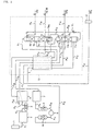
- feed air (1,000 Nm 3 /h) is introduced into an air filter 1 so as to be freed of dust, and this feed air freed of dust is introduced into a compressor 2 through a pipe P1 so as to be compressed to a pressure necessary for air separation, for example to 3.8 ata.
- a Freon refrigerator 3 After the compressed feed air is then passed through a Freon refrigerator 3 through a pipe P2 so as to be cooled down, it is fed to a decarbonating drier 4 through a pipe P3.
- This decarbonating drier 4 comprises two molecular sieve columns which are alternately switched over for use, where the feed air will be fed to one of them so that carbon dioxide (CO 2 ) and moisture (H 2 O) and sulfides such as SOx and H 2 S which become catalyst poisons of an oxidation catalyst, contained in the feed air, are removed by adsorption.
- waste gas impure oxygen gas
- a main heat exchanger 5 which will be hereinafter mentioned is fed as a regeneration gas for the decarbonating drier 4.
- the feed air ascending from the lower portion and liquid nitrogen (reflux liquid) descending from the inner upper portion of the low-pressure rectification column 6 are therefore brought into countercurrent contact with each other, whereby oxygen in the feed air is liquefied, SOx and H 2 S which become catalyst poisons are completely removed and low purity nitrogen gas containing the remaining oxygen component is separated by rectification.
- the reflux liquid descending from the upper portion and reboil gas formed in the bottom portion are brought in countercurrent contact with each other, whereby nitroggen in the reflux liquid is evaporated, oxygen in the reboil gas is liquefied and the liquefied oxygen is led to a reboiler-condenser 6RC in the inner lower portion of the low-pressure rectification column 6 as oxygen-rich liquid air.
- said low purity nitrogen gas nitrogen gas containing an oxygen component, i.e. raw nitrogen gas
- This raw nitrogen gas is fed to the main heat exchanger 5 through a pipe P7 so as to be used as a cold source for the main heat exchanger 5.
- Raw nitrogen gas led out of the main heat exchanger 5 gets normal temperature and a pressure of 3.1 ata.
- This raw nitrogen gas is further introduced to a recycle compressor 7 by way of a pipe P8 so as to be compressed to a pressure of 9.3 ata, and then led to an oxidation column 8 filled with an oxidation catalyst through a pipe P9.
- the feed raw nitrogen gas ascends through the rectifying portions 11b, 11d, in the intermediate-pressure rectification column 11, it is brought into contact with the descending reflux liquid so as to liquefy its oxygen component, and reservoired in the bottom portion of the intermediate-pressure rectification column 11 as oxygen-rich liquid air.
- the rectified nitrogen gas freed of oxygen component is taken out of the top portion of the intermediate-pressure rectification column 11 and led into the reboiler-condenser 6RC in the lower portion of the low-pressure rectification column 6 through a pipe P14.
- the rectified nitrogen gas is liquefied, the thus-obtained liquid nitrogen is returned to a reservoir portion R1 in the upper portion of the intermediate-pressure rectification column 11 through a pipe P15, and impurities which have not been liquefied such as helium (He), hydrogen (H 2 ) and neon (Nc) are discharged from the lower portion of the reboilewr-condenser 6RC through a pipe P16.
- impurities which have not been liquefied such as helium (He), hydrogen (H 2 ) and neon (Nc) are discharged from the lower portion of the reboilewr-condenser 6RC through a pipe P16.
- Said liquid nitrogen returned to the reservoir portion R1 of the intermediate-pressure rectification column 11 is of high purity nitrogen least containing components other than nitrogen.
- this liquid nitrogen is caused to flow down from the reservoir portion R1 through a rectifying portion lld consisting of plural rectifying stages.
- the resulting ultra-high purity nitrogen gas is taken out of a take-out portion 11c in the middle portion of the intermediate-pressure rectification column 11 through a pipe P17, it is led to the main heat exchanger 5 so as to get normal temperature.
- nitrogen gas is freed of fine dust by means of a particle filter (dust filter) 12 provided on a pipe P18, it is taken out at a pressure of about 8.3 ata and at a flow rate of about 700 Nm 3 /h as a gas product. Further, from the reservoir portion R2 of the intermediate-pressure rectification column 11, an ultra-high purity liquid nitrogen product is taken out in a liquid state through a pipe P19.
- a particle filter dust filter
- the liquid nitrogen in which the oxygen component has been concentrated in the bottom portion of the intermediate-pressure rectification column 11 is passed through a pipe P20 and expanded to 3.3 ata by an expansion valve V1 provided on the pipe P20, and the expanded liquid nitrogen is fed to the upper portion of the low-pressure rectification column 6 as cold and feed nitrogen so as to be used as a reflux liquid and feed nitrogen to the low-pressure rectification column 6.
- the oxygen-rich liquid air in the bottom portion of the low-pressure rectification column 6 is used as a cold source in the reboiler-condenser 6RC disposed in the bottom portion of the low-pressure rectification column 6 so as to be evaporated in itself.
- a part of this oxygen-rich gas is returned as reboil gas to the bottom portion of the low-pressure rectification column 6, and the remaining oxygen-rich gas is passed through a pipe P21 to recover cold as a cold source for the main heat exchanger 5.
- the oxygen-rich gas which has got normal temperature due to heat exchange in the main heat exchanger 5 is led to the other molecular sieve column of the decarbonating drier 4 through a pipe P22 so as to be used as a regeneration gas for the decarbonating drier 4. and then discharged as waste gas through a pipe P23.
- a part 13 surrounded by a dotted line is a cold box.
- the main heat exchanger 5, low-pressure rectification column 6, intermediate-pressure rectification column 11, expansion valve V1 and pipes thereof are accomodated in the inside of said cold box 13.
- This cold box 13 is thermally insulated from the atmospheric air because it is a low-temperature portion.
- liquid nitrogen is fed, in an amount as large as about 1/100 of the feed air fed to the compressor 2 through the pipe P1, from the outside into the low-pressure rectification column 6 by way of the pipe P6.
- the liquid nitrogen which has been fed by way of the pipe P6, as mentioned above, is passed through the same route as the feed air and roughly rectified by the low-pressure rectification column 6, it is led to the oxidation column 8 and adsorption column 10, where impurities such as carbon monoxide and catalyst poisons are removed therefrom.
- liquid nitrogen for back-up use is roughly rectified as a feed gas in the low-pressure rectifcation column 6.
- carbon monoxide and hydrogen in raw nitrogen gas obtained in the low-pressure rectification column 6 are converted to carbon dioxide and water in the oxidation column 8, respectively, they are removed by adsorption in the adsorption column 10.
- the same nitrogen gas is fed to the intermediate-pressure rectification column 11.
- Cold energy of the liquid nitrogen for back-up use is fed to the intermediate-pressure rectification column 11 by way of the reboiler-condenser 6RC. Accordingly, a nitrogen component and cold energy in the liquid nitrogen for back-up use can be recovered about 100% and ultra-high purity nitrogen can be produced even at the back-up time.
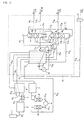
- such cold may be generated by use of an expansion turbine as in the second embodiment illustrated in Fig.2.
- waste gas oxygen-rich gas
- a passage for the waste gas is divided to two passages before it gets into the main heat exchanger 5.
- a pipe P30 which is one branched passage has a shut-off valve V2 provided thereon, and a pipe P31 which is the other branched passage extends through the main heat exchanger 5 from its low-temperature side to the way between the low-temperature side and normal temperature side.
- Said pipe P31 has a shut-off valve V3 and expansion turbine 15 provided thereon outside of the main heat exchanger 5.
- Cold generated in the expansion turbine 15 is joined to the pipe P30 by way of a pipe P32, and introduced into the main heat exchanger 5 so as to be used as a cold source therefor.
- the amount of cold is increased or decreased by adjusting the open degree of the shut-off valves V 2 , V 3 to regulate the flow rate of gas passing through the expansion turbine 15, with no supply of cold from the outside. Since the amount of cold can be therefore made to correspond to the amounts of liquid nitrogen and nitrogen gas to be taken out as products, it is possible to stabilize the operation of the whole of the unit.
- Fig. 3 shows a third embodiment of the present invention.
- the feed raw nitrogen gas which has been freed of carbon dioxide and moisture by adsorption is introduced into the main heat exchanger 5 through the pipe P12.
- this third embodiment illustrated in Fig. 3 it is devised that after a part of feed raw nitrogen gas is taken out of the way between the low temperature side and normal temperature side of the main heat exchanger 5 through a pipe P33 and adiabatically expanded by the expansion turbine 15, it is joined, by a pipe P34. with raw nitrogen gas for recycle use taken out of the top portion of the low-pressure rectification column 6 through the pipe P7 and then introduced into the main heat exchanger 5
- a shut-off valve V4 and the expansion turbine 15 are inserted in series in the pipe P33, a pipe P35 is connected in parallel to both the ends of this series connection of said shut-off valve V4 and expansion turbine 15, and a shut-off valve V5 is provided in this pipe P35.
- the reboiler-condenser 6RC is made in one body with the low-pressure rectification column 6 in the aforementioned embodiment, it may be provided separately from the low-pressure rectification column 6.
- the catalyst activity can be semi-permamently maintained because feed air is passed through the oxidation column after catalyst poisons such as SOx and H 2 S are removed through the normal temperature purification and the low temperature liquefying rectification in the low-pressure rectification column. Futher, ultra-high purity nitrogen can be recovered at a higher yield because low purity nitrogen separated by the low temperature liquefying rectification is recycled.
- liquid nitrogen fed at the back-up time is fed to the low-pressure rectification clomun so as to be subjected to low temperature liquefying rectification and then passed through the oxidation column and adsorption column, it is possible to reliably remove catalyst poisons such as SOx and H 2 S, carbon monoxide and hydrogen, without providing any special impurity removing facilities. Furthermore, since it is constructed that cold energy of liquid nitrogen for back-up use is recovered 100%, it is possible to produce ultra-hgh purity nitrogen at a higher yield even at the back-up time.
- Fig. 1 is a flow diagram showing a first embodiment of an ultra-high purity nitrogen generating method and unit according to the present invention:
Landscapes
- Engineering & Computer Science (AREA)
- General Engineering & Computer Science (AREA)
- Physics & Mathematics (AREA)
- Thermal Sciences (AREA)
- Mechanical Engineering (AREA)
- Chemical & Material Sciences (AREA)
- Chemical Kinetics & Catalysis (AREA)
- Analytical Chemistry (AREA)
- Oil, Petroleum & Natural Gas (AREA)
- General Chemical & Material Sciences (AREA)
- Health & Medical Sciences (AREA)
- Emergency Medicine (AREA)
- Separation By Low-Temperature Treatments (AREA)
- Separation Of Gases By Adsorption (AREA)
- Exhaust Gas Treatment By Means Of Catalyst (AREA)
Applications Claiming Priority (2)
| Application Number | Priority Date | Filing Date | Title |
|---|---|---|---|
| JP185933/95 | 1995-07-21 | ||
| JP7185933A JPH0933166A (ja) | 1995-07-21 | 1995-07-21 | 超高純度窒素製造方法及び装置 |
Publications (2)
| Publication Number | Publication Date |
|---|---|
| EP0754923A2 true EP0754923A2 (fr) | 1997-01-22 |
| EP0754923A3 EP0754923A3 (fr) | 1997-09-10 |
Family
ID=16179426
Family Applications (1)
| Application Number | Title | Priority Date | Filing Date |
|---|---|---|---|
| EP96401577A Ceased EP0754923A3 (fr) | 1995-07-21 | 1996-07-16 | Procédé et dispositif de production d'azote d'ultra haute pureté |
Country Status (5)
| Country | Link |
|---|---|
| US (1) | US5682761A (fr) |
| EP (1) | EP0754923A3 (fr) |
| JP (1) | JPH0933166A (fr) |
| KR (1) | KR970005363A (fr) |
| CN (1) | CN1152702A (fr) |
Cited By (6)
| Publication number | Priority date | Publication date | Assignee | Title |
|---|---|---|---|---|
| EP1316769A1 (fr) * | 2001-11-28 | 2003-06-04 | Linde Aktiengesellschaft | Procédé et dispositif pour la production d'azote ultra pur à partir d'azote moins pur |
| CN109442867A (zh) * | 2018-12-19 | 2019-03-08 | 杭州特盈能源技术发展有限公司 | 一种新型外增压内液化纯氮制取装置及方法 |
| CN110195962A (zh) * | 2019-06-05 | 2019-09-03 | 杭州凯德空分设备有限公司 | 垃圾填埋气、沼气或化工尾气提取高纯二氧化碳工艺设备 |
| CN110207457A (zh) * | 2019-06-08 | 2019-09-06 | 苏州制氧机股份有限公司 | 一种能制液氮的空分设备及其使用方法 |
| CN111268658A (zh) * | 2020-03-11 | 2020-06-12 | 苏州市兴鲁空分设备科技发展有限公司 | 氩尾气回收净化方法和系统 |
| CN113758149A (zh) * | 2021-09-30 | 2021-12-07 | 河南心连心深冷能源股份有限公司 | 一种双制冷方式生产电子级一氧化碳的装置及方法 |
Families Citing this family (7)
| Publication number | Priority date | Publication date | Assignee | Title |
|---|---|---|---|---|
| JP3719832B2 (ja) * | 1997-10-14 | 2005-11-24 | 日本エア・リキード株式会社 | 超高純度窒素及び酸素の製造装置 |
| JP4078787B2 (ja) * | 2000-03-31 | 2008-04-23 | Jsr株式会社 | 化学機械研磨用水系分散体 |
| CN101487656B (zh) * | 2009-02-11 | 2010-12-01 | 王有良 | 一种液化气体中液体杂质的液相分离方法 |
| CN102213537A (zh) * | 2011-04-18 | 2011-10-12 | 开封黄河空分集团有限公司 | 低压富氧空气分离工艺 |
| DE102015004120A1 (de) * | 2015-03-31 | 2016-10-06 | Linde Aktiengesellschaft | Verfahren zum Abtrennen von Stickstoff aus einer Kohlenwasserstoff-reichen Fraktion |
| CN106500461A (zh) * | 2016-12-20 | 2017-03-15 | 上海华林工业气体有限公司 | 具有加速预冷效果的hyco冷箱系统及其加速预冷方法 |
| CN113776279B (zh) * | 2021-09-29 | 2025-02-28 | 河南心连心化学工业集团股份有限公司 | 一种空气分离装置中的污氮气用脱氧装置及脱氧净化工艺 |
Family Cites Families (3)
| Publication number | Priority date | Publication date | Assignee | Title |
|---|---|---|---|---|
| FR2695714B1 (fr) * | 1992-09-16 | 1994-10-28 | Maurice Grenier | Installation de traitement cryogénique, notamment de distillation d'air. |
| JP2893562B2 (ja) * | 1992-09-22 | 1999-05-24 | 日本エア・リキード株式会社 | 超高純度窒素製造方法及びその装置 |
| FR2706025B1 (fr) * | 1993-06-03 | 1995-07-28 | Air Liquide | Installation de distillation d'air. |
-
1995
- 1995-07-21 JP JP7185933A patent/JPH0933166A/ja active Pending
-
1996
- 1996-07-16 EP EP96401577A patent/EP0754923A3/fr not_active Ceased
- 1996-07-19 US US08/684,057 patent/US5682761A/en not_active Expired - Fee Related
- 1996-07-19 CN CN96112257A patent/CN1152702A/zh active Pending
- 1996-07-20 KR KR1019960029496A patent/KR970005363A/ko not_active Withdrawn
Cited By (10)
| Publication number | Priority date | Publication date | Assignee | Title |
|---|---|---|---|---|
| EP1316769A1 (fr) * | 2001-11-28 | 2003-06-04 | Linde Aktiengesellschaft | Procédé et dispositif pour la production d'azote ultra pur à partir d'azote moins pur |
| CN109442867A (zh) * | 2018-12-19 | 2019-03-08 | 杭州特盈能源技术发展有限公司 | 一种新型外增压内液化纯氮制取装置及方法 |
| CN109442867B (zh) * | 2018-12-19 | 2023-11-07 | 杭州特盈能源技术发展有限公司 | 一种外增压内液化纯氮制取装置及方法 |
| CN110195962A (zh) * | 2019-06-05 | 2019-09-03 | 杭州凯德空分设备有限公司 | 垃圾填埋气、沼气或化工尾气提取高纯二氧化碳工艺设备 |
| CN110207457A (zh) * | 2019-06-08 | 2019-09-06 | 苏州制氧机股份有限公司 | 一种能制液氮的空分设备及其使用方法 |
| CN110207457B (zh) * | 2019-06-08 | 2023-12-08 | 苏州制氧机股份有限公司 | 一种能制液氮的空分设备及其使用方法 |
| CN110207457B8 (zh) * | 2019-06-08 | 2023-12-29 | 苏州制氧机股份有限公司 | 一种能制液氮的空分设备及其使用方法 |
| CN111268658A (zh) * | 2020-03-11 | 2020-06-12 | 苏州市兴鲁空分设备科技发展有限公司 | 氩尾气回收净化方法和系统 |
| CN111268658B (zh) * | 2020-03-11 | 2024-03-22 | 苏州市兴鲁空分设备科技发展有限公司 | 氩尾气回收净化方法和系统 |
| CN113758149A (zh) * | 2021-09-30 | 2021-12-07 | 河南心连心深冷能源股份有限公司 | 一种双制冷方式生产电子级一氧化碳的装置及方法 |
Also Published As
| Publication number | Publication date |
|---|---|
| EP0754923A3 (fr) | 1997-09-10 |
| US5682761A (en) | 1997-11-04 |
| JPH0933166A (ja) | 1997-02-07 |
| KR970005363A (ko) | 1997-02-19 |
| CN1152702A (zh) | 1997-06-25 |
Similar Documents
| Publication | Publication Date | Title |
|---|---|---|
| US5373699A (en) | Process for the production of nitrogen by cryogenic distillation of atmospheric air | |
| EP0589646B1 (fr) | Procédé de distillation pour la production d'azote dépourvu de monoxyde de carbone | |
| US20120131951A1 (en) | Air liquefaction separation method and apparatus | |
| US5682761A (en) | Ultra-high purity nitrogen generating method and unit | |
| US4867773A (en) | Cryogenic process for nitrogen production with oxygen-enriched recycle | |
| EP0773417A2 (fr) | Procédé et dispositif pour la production d'azote par séparation d'air | |
| JPH05157448A (ja) | 供給材料空気流れを構成成分に分離する極低温法 | |
| EP0811816A2 (fr) | Procédé et dispositif de production de produits liquides d'air en proportions variables | |
| US5037462A (en) | Process and device for production of nitrogen | |
| EP0762066B1 (fr) | Production d'oxygène ultra-pur des installations cryogéniques de séparations d'air | |
| JPH07151462A (ja) | 高圧の酸素及び窒素製品を製造する圧縮原料空気の低温分離法 | |
| JPH05296651A (ja) | 超高純度窒素・酸素製造装置 | |
| US6351971B1 (en) | System and method for producing high purity argon | |
| EP0589766B1 (fr) | Procédé et appareillage pour la production d'azote ultra-pur | |
| EP0532155B2 (fr) | Procédé cryogénique pour la production de l'azote d'ultra-haute pureté | |
| EP0283213B1 (fr) | Procédé de récupération de l'argon | |
| JP3190016B2 (ja) | 高圧窒素を製造する原料空気の低温蒸留方法 | |
| JPH11118351A (ja) | 超高純度窒素及び酸素の製造装置 | |
| JP3748677B2 (ja) | 低純度酸素の製造方法及び装置 | |
| JP3667889B2 (ja) | 窒素製造方法及び装置 | |
| JPS61276680A (ja) | 空気液化分離方法 | |
| EP0821211A2 (fr) | Système cryogénique hybride pour la production de l'oxygène à basse et haute pureté | |
| JPH11132652A (ja) | 低純度酸素の製造方法及び装置 | |
| JP2000018813A (ja) | 窒素製造方法及び装置 | |
| JPH10259989A (ja) | 空気分離方法および空気分離装置 |
Legal Events
| Date | Code | Title | Description |
|---|---|---|---|
| PUAI | Public reference made under article 153(3) epc to a published international application that has entered the european phase |
Free format text: ORIGINAL CODE: 0009012 |
|
| AK | Designated contracting states |
Kind code of ref document: A2 Designated state(s): DE FR GB IT NL |
|
| PUAL | Search report despatched |
Free format text: ORIGINAL CODE: 0009013 |
|
| AK | Designated contracting states |
Kind code of ref document: A3 Designated state(s): DE FR GB IT NL |
|
| 17P | Request for examination filed |
Effective date: 19980310 |
|
| RAP1 | Party data changed (applicant data changed or rights of an application transferred) |
Owner name: L'AIR LIQUIDE S.A. Owner name: AIR LIQUIDE JAPAN, LTD. |
|
| 17Q | First examination report despatched |
Effective date: 20000407 |
|
| RAP1 | Party data changed (applicant data changed or rights of an application transferred) |
Owner name: L'AIR LIQUIDE, S.A. A DIRECTOIRE ET CONSEIL DE SU Owner name: AIR LIQUIDE JAPAN, LTD. |
|
| GRAG | Despatch of communication of intention to grant |
Free format text: ORIGINAL CODE: EPIDOS AGRA |
|
| STAA | Information on the status of an ep patent application or granted ep patent |
Free format text: STATUS: THE APPLICATION HAS BEEN REFUSED |
|
| 18R | Application refused |
Effective date: 20021115 |