EP0756207A2 - Procédé de positionnement d'un masque par rapport à un autre masque ou une pièce à traiter et dispositif de mise en oeuvre de ce procédé - Google Patents
Procédé de positionnement d'un masque par rapport à un autre masque ou une pièce à traiter et dispositif de mise en oeuvre de ce procédé Download PDFInfo
- Publication number
- EP0756207A2 EP0756207A2 EP96112043A EP96112043A EP0756207A2 EP 0756207 A2 EP0756207 A2 EP 0756207A2 EP 96112043 A EP96112043 A EP 96112043A EP 96112043 A EP96112043 A EP 96112043A EP 0756207 A2 EP0756207 A2 EP 0756207A2
- Authority
- EP
- European Patent Office
- Prior art keywords
- mask
- alignment marks
- workpiece
- light
- projection lens
- Prior art date
- Legal status (The legal status is an assumption and is not a legal conclusion. Google has not performed a legal analysis and makes no representation as to the accuracy of the status listed.)
- Granted
Links
Images


Classifications
-
- G—PHYSICS
- G03—PHOTOGRAPHY; CINEMATOGRAPHY; ANALOGOUS TECHNIQUES USING WAVES OTHER THAN OPTICAL WAVES; ELECTROGRAPHY; HOLOGRAPHY
- G03F—PHOTOMECHANICAL PRODUCTION OF TEXTURED OR PATTERNED SURFACES, e.g. FOR PRINTING, FOR PROCESSING OF SEMICONDUCTOR DEVICES; MATERIALS THEREFOR; ORIGINALS THEREFOR; APPARATUS SPECIALLY ADAPTED THEREFOR
- G03F9/00—Registration or positioning of originals, masks, frames, photographic sheets or textured or patterned surfaces, e.g. automatically
- G03F9/70—Registration or positioning of originals, masks, frames, photographic sheets or textured or patterned surfaces, e.g. automatically for microlithography
- G03F9/7003—Alignment type or strategy, e.g. leveling, global alignment
- G03F9/7023—Aligning or positioning in direction perpendicular to substrate surface
- G03F9/7026—Focusing
-
- G—PHYSICS
- G03—PHOTOGRAPHY; CINEMATOGRAPHY; ANALOGOUS TECHNIQUES USING WAVES OTHER THAN OPTICAL WAVES; ELECTROGRAPHY; HOLOGRAPHY
- G03F—PHOTOMECHANICAL PRODUCTION OF TEXTURED OR PATTERNED SURFACES, e.g. FOR PRINTING, FOR PROCESSING OF SEMICONDUCTOR DEVICES; MATERIALS THEREFOR; ORIGINALS THEREFOR; APPARATUS SPECIALLY ADAPTED THEREFOR
- G03F7/00—Photomechanical, e.g. photolithographic, production of textured or patterned surfaces, e.g. printing surfaces; Materials therefor, e.g. comprising photoresists; Apparatus specially adapted therefor
- G03F7/70—Microphotolithographic exposure; Apparatus therefor
- G03F7/70425—Imaging strategies, e.g. for increasing throughput or resolution, printing product fields larger than the image field or compensating lithography- or non-lithography errors, e.g. proximity correction, mix-and-match, stitching or double patterning
-
- G—PHYSICS
- G03—PHOTOGRAPHY; CINEMATOGRAPHY; ANALOGOUS TECHNIQUES USING WAVES OTHER THAN OPTICAL WAVES; ELECTROGRAPHY; HOLOGRAPHY
- G03F—PHOTOMECHANICAL PRODUCTION OF TEXTURED OR PATTERNED SURFACES, e.g. FOR PRINTING, FOR PROCESSING OF SEMICONDUCTOR DEVICES; MATERIALS THEREFOR; ORIGINALS THEREFOR; APPARATUS SPECIALLY ADAPTED THEREFOR
- G03F9/00—Registration or positioning of originals, masks, frames, photographic sheets or textured or patterned surfaces, e.g. automatically
- G03F9/70—Registration or positioning of originals, masks, frames, photographic sheets or textured or patterned surfaces, e.g. automatically for microlithography
- G03F9/7003—Alignment type or strategy, e.g. leveling, global alignment
-
- G—PHYSICS
- G03—PHOTOGRAPHY; CINEMATOGRAPHY; ANALOGOUS TECHNIQUES USING WAVES OTHER THAN OPTICAL WAVES; ELECTROGRAPHY; HOLOGRAPHY
- G03F—PHOTOMECHANICAL PRODUCTION OF TEXTURED OR PATTERNED SURFACES, e.g. FOR PRINTING, FOR PROCESSING OF SEMICONDUCTOR DEVICES; MATERIALS THEREFOR; ORIGINALS THEREFOR; APPARATUS SPECIALLY ADAPTED THEREFOR
- G03F9/00—Registration or positioning of originals, masks, frames, photographic sheets or textured or patterned surfaces, e.g. automatically
- G03F9/70—Registration or positioning of originals, masks, frames, photographic sheets or textured or patterned surfaces, e.g. automatically for microlithography
- G03F9/7073—Alignment marks and their environment
- G03F9/7084—Position of mark on substrate, i.e. position in (x, y, z) of mark, e.g. buried or resist covered mark, mark on rearside, at the substrate edge, in the circuit area, latent image mark, marks in plural levels
Definitions
- the invention relates to a process for positioning of one mask relative to another mask or positioning of a plurality of masks relative to a workpiece, and to a device for executing the process in an exposure device which is used for production of a semiconductor device, a printed board, a liquid crystal display and the like.
- These electronic parts are semiconductor components, liquid crystal displays, printer heads of the ink jet type, multichip modules in which a plurality of various electronic components are produced on a substrate and thus a module is formed, and the like.
- a double-sided exposure system is used as one of these exposure systems, in which mask patterns, which are located above and below the workpiece, are transferred to both of its sides.
- the masks located above and below are positioned relative to one another, and thus, the patterns which are transferred to the surface and back of the workpiece are positioned relative to one another. Then, the masks are positioned relative to the workpiece. Patterns to be subsequently transferred are positioned exactly relative to the patterns on the workpiece which were formed beforehand.
- the above described positioning is conventionally done such that alignment marks of the two masks come to lie on top of one another, and that the alignment marks of the masks and the workpiece come to lie on top of one another.
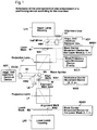
- Fig. 6 schematically shows the conventional positioning of the masks relative to one another and of the masks relative to the workpiece in the above described double-sided exposure system.
- top mask M1 a bottom mask M2, top and bottom projection lenses L1 and L2, and alignment units A1, A2, each of which comprise, for example, a mirror, two lenses and an imager (CCD)
- alignment units A1, A2 each of which comprise, for example, a mirror, two lenses and an imager (CCD)
- a dummy D for positioning of upper mask M1 relative to lower mask M2 is provided having dummy alignment marks DAM on both side thereof.
- the invention was made to eliminate the above described disadvantages in the prior art.
- a first object of the invention is to devise a process for positioning of one mask relative to another, in which a dummy is not used, and in which, furthermore, deviations of the positional relationship of an upper mask to a lower mask as a result of temperature changes can be easily corrected, and to devise a device for executing the process.
- a second object of the invention is to devise a process for positioning an upper mask and a lower mask relative to a workpiece, in which no aberration correction is necessary, in which, furthermore, it is unnecessary to produce a projection lens which has small aberration both with respect to the light with exposure wavelengths and also with respect to the light with nonexposure wavelengths, and to devise a device for executing the process.
- a third object of the invention is to devise a process for positioning an upper mask and a lower mask relative to a workpiece, in which multichromatic light can be used as the light source for alignment, in which no interference bands are formed which are caused by variation of the resist layer thickness, and in which alignment marks are easily determined, and to devise a device for executing the process.
- a fourth object of the invention is to devise a process for positioning an upper mask and a lower mask relative to a workpiece in which, during positioning, the resist on the workpiece is not exposed to the action of exposure light, and in which circuit patterns can be formed in the areas used for positioning, and to devise a device for executing the process.
- positioning of one mask relative to another mask is done by emitting light with exposure wavelengths from a first light irradiation part onto alignment marks of a first mask, by recording alignment marks of the second mask and the projection images of the alignment marks of the first mask and subjecting them to image processing, projecting them through a first projection lens and a second projection lens onto the second mask, in which at least the sides opposite the mask sides are telecentric, by computing the data of the relative positions of the two alignment marks, and by moving the second mask and/or the first mask such that the above described two alignment marks come to lie on top of one another.
- the above described objects are achieved according to a second embodiment in that positioning of masks relative to a workpiece is performed in a state in which the workpiece is remote, light with exposure wavelengths is emitted from a first light irradiation part onto alignment marks of a first mask, the alignment marks of a second mask and projection images of the alignment marks of the first mask are recorded and are projected onto the second mask through a first projection lens and a second projection lens, in which at least the sides of the lenses opposite the workpiece sides are telecentric, then the relative positions of the two alignment marks are determined, and based on data of the relative positions of the above described two alignment marks, the second mask and/or the first mask is/are moved such that the two alignment marks come to lie on top of one another.
- the light which irradiates the alignment marks of the first mask is deflected or branched between the first projection lens and the second projection lens, the alignment marks of the first mask are recorded, the relative positions thereof are determined/stored, after which emission of the light with the exposure wavelengths from the first light irradiation part is stopped, a workpiece is inserted in a predetermined position between the first projection lens and the second projection lens, and light with nonexposure wavelengths is emitted from a second light irradiation part onto alignment marks of the workpiece, the alignment marks of the workpiece are recorded and their relative positions are determined/stored. Based on the previously stored data of the relative positions of the alignment marks of the first mask and based on data of the relative positions of the alignment marks of the workpiece, the workpiece is moved such that the two come to lie on top of one another.
- the above described objects are achieved according to a third embodiment in that positioning of masks to a workpiece is done by the fact that in a state in which the workpiece is remote, from a first light irradiation part light with exposure wavelengths is emitted onto alignment marks of a first mask, that the light which irradiates the alignment marks of the above described first mask is transmitted by a first projection lens, in which at least the workpiece side is telecentric, that the above described transmission light is branched into first branched light and second branched light, that the above described first branched light is transmitted by a second projection lens in which at least the workpiece side is telecentric, that projection images of the alignment marks of the first mask which are projected onto the second mask, and alignment marks of the second mask are recorded, that relative positions of the two alignment marks are determined, that using the above described second branched light the alignment marks of the above described first mask are recorded, that the relative positions thereof are determined/stored, that based on data of the relative positions of the above described two alignment marks the second
- a fourth embodiment in that, in a device for positioning one mask relative to another mask, there are a first mask, a first mask carrier movement device for moving the first mask, a first projection lens, of which at least the side opposite the mask side is telecentric, a second mask, a second mask carrier movement device for moving the second mask, a second projection lens, of which at least the side opposite the mask side is telecentric, a light irradiation part for irradiating alignment marks of the first mask with light with the exposure wavelengths, a camera means which records projection images of the alignment marks of the first mask by the light with exposure wavelengths emitted from the light irradiation part and records the alignment marks of the second mask, and a control means which, based on the image data recorded by the camera means controls the first mask carrier movement part and/or the second mask carrier movement part.
- control means records the alignment marks of the second mask and the projection images of the alignment marks of the first mask which are projected through the first projection lens and the second projection lens onto the second mask, performs image processing and determines the relative positions thereof, if the light irradiation part emits light with exposure wavelengths, and the control means computes the data of the relative positions of the two alignment marks and moves the second mask and/or the first mask such that the two alignment marks come to lie on top of one another.
- a first mask in a device for positioning of masks relative to a workpiece, there are a first mask, a first mask carrier movement device for moving the above described first mask, a first projection lens, of which at least the side opposite the mask side is telecentric, a workpiece, a workpiece carrier movement device for moving the workpiece, a second mask, a second mask carrier movement device for moving the second mask, a second projection lens, in which at least the side opposite the mask side is telecentric, a first light irradiation part for irradiating alignment marks of the first mask with light with exposure wavelengths, a second light irradiation part for irradiating alignment marks of the workpiece with light with nonexposure wavelengths, a first camera means which records projection images of the alignment marks of the first mask by the light with exposure wavelengths emitted from the first light irradiation part and records the alignment marks of the second mask, a light branching means for branching the light which ir
- a control means which, based on the image data recorded by the first camera means, controls the first mask carrier movement device and/or the second mask carrier movement device, which controls the first mask carrier movement device and/or the second mask carrier movement device based on the image data recorded by the first camera means, and which controls the workpiece carrier movement device based on the image data recorded by the second camera means.
- the control means In the state in which the workpiece is remote, the control means has the light irradiation part emit light with exposure wavelengths, the control means records the alignment marks of the second mask and the projection images of the alignment marks of the first mask which are projected through the first projection lens and the second projection lens onto the second mask, performs image processing and determines the relative positions thereof, then the control means computes data of the relative positions of the alignment marks of the second mask and the projection images of the alignment marks of the first mask, moves the second mask and/or the first mask such that the two come to lie on top of one another.
- control means records the projection images of the alignment marks of the above described first mask by the branched light in which the light irradiating the alignment marks of the above described first mask was branched between the first projection lens and the second projection lens, or by the deflected light in which the irradiation light was deflected, performs image processing and determines/stores the relative positions thereof, after which the control means stops emission of light with exposure wavelengths from the first light irradiation part and inserts the workpiece in a predetermined position between the first projection lens and the second projection lens.
- control means has the second light irradiation part emit light with nonexposure wavelengths, records the alignment marks of the workpiece, performs image processing and determines the relative positions thereof, and based on the previously stored data of the relative positions of the alignment marks of the first mask and based on the data of the relative positions of the alignment marks of the workpiece, the control means moves the workpiece such that the two come to rest on top of one another.
- a first mask in a device for positioning of masks relative to a workpiece, there are a first mask, a first mask carrier movement device for moving the above described first mask, a first projection lens, of which at least the side opposite the mask is telecentric, a workpiece, a workpiece carrier movement device for moving the workpiece, a second mask, a second mask carrier movement device for moving the second mask, a second projection lens, of which at least the side opposite the mask is telecentric, a first light irradiation part for irradiating alignment marks of the first mask with light with the exposure wavelengths, a second light irradiation part for irradiating alignment marks of the workpiece with light with nonexposure wavelengths, a first camera means which records projection images of the alignment marks of the first mask by the light with exposure wavelengths emitted from the first light irradiation part and records the alignment marks of the second mask, a light branching means for branching of the light which ir
- the control means has the light irradiation part emit light with exposure wavelengths, and the control means records the alignment marks of the second mask and the projection images of the alignment marks of the first mask which are projected through the first projection lens and the second projection lens onto the second mask, performs image processing, and determines the relative positions thereof.
- the control means records the projected images of the alignment marks of the first mask by the branched light in which the light which irradiates the alignment marks of the first mask was branched between the first objective lens and the second objective lens, performs image processing and determines/stores the relative positions thereof.
- the control means computes data of the relative positions of the alignment marks of the second mask and the projected images of the alignment marks of the first mask, causes the second mask and/or the first mask to be moved such that the two come to lie on top of one another, and then the control means stops emission of the light with exposure wavelengths from the first light irradiation part and inserts the workpiece in a predetermined position between the first projection lens and the second projection lens, and has the second light irradiation part emit light with nonexposure wavelengths, records the alignment marks of the workpiece, performs image processing and determines the relative positions thereof. Additionally, the control means, based on the previously stored data of the relative positions of the alignment marks of the first mask and based on the data of the relative positions of the alignment marks of the workpiece causes the movement of the workpiece such that the two come to rest on top of one another.
- light with exposure wavelengths is emitted from the light irradiation part onto the alignment marks of the first mask.
- the alignment marks of the second mask and the projection images of the alignment marks of the first mask are recorded and undergo image processing and are projected through the first projection lens and the second projection lens onto the second mask, of which at least the sides opposite the mask sides are telecentric, and their relative positions are determined.
- the data of the relative positions of the two alignment marks are computed and the second mask and/or the first mask is moved such that the two alignment marks come to lie on top of one another.
- positioning of one mask relative to another mask is performed in the same way as with respect to the first and fourth embodiments, and furthermore, the light which irradiates the alignment marks of the first mask is branched or deflected, the alignment marks of the first mask are recorded, their relative positions are determined/ stored, then emission of the light with exposure wavelengths from the first light irradiation part is stopped, the workpiece is inserted in a predetermined position, the light with nonexposure wavelengths is emitted onto the alignment marks of the workpiece, the relative positions of the alignment marks of the workpiece are determined/stored and based on the previously stored data of the relative positions of the alignment marks of the first mask and based on the data of the relative positions of the workpiece, the workpiece is moved such that the two come to lie on top of one another.
- multichromatic light with nonexposure wavelengths can be used as the light which illuminates the alignment marks of the workpiece. Therefore, the alignment marks can be easily determined without formation of the above described interference bands or the like. Therefore, it is unnecessary to use an extra irradiation unit for the light with exposure wavelengths for purposes of partial illumination. Furthermore, exposure of the resist on the workpiece due to the action of exposure light during positioning is prevented, by which effective use of the alignment areas on the workpiece is enabled.
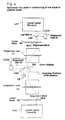
- Fig. 1 is a schematic depiction of an embodiment of a positioning device according to the invention in which an upper lamp housing LH1 and a lower lamp housing LH2 each contain a lamp (not shown) from which light with exposure wavelengths is emitted for irradiating upper and lower masks M1, M2 (described below) via shutters, optical filters, condenser lenses, and the like.
- a first alignment unit A1 is comprised of a half mirror HM1, two lenses (not shown), an imager CCD1 or the like. By means of first alignment units A1, the alignment marks of the first mask M1 and a workpiece W are recorded. Alignment units A1 are inserted and removed by alignment unit insertion and removal devices AD1.
- Upper mask M1 and lower mask M2 are recorded patterns for projection onto the workpiece W and mask alignment marks MA1 and MA2.
- Upper mask M1 and lower mask M2 are, furthermore, attached to mask carriers (not shown) and these mask carriers are moved by means of a mask carrier movement device for the upper mask MSD1 and a mask carrier movement device for the lower mask MSD2 in the X-Y- ⁇ directions (i.e., to the right, left, front and back in the drawing and in a direction of rotation around an axis which is perpendicular to the mask surfaces).
- Reference numbers L1 and L2 designate projection lenses which, in this embodiment, are telecentric lenses in which both sides, i.e., both the workpiece side of the lenses L1 and L2 and the mask side of the lenses L1 and L2, are telecentric.
- lenses which are telecentric on only one side can also be used, in which only the lenses on the workpiece sides of projection lenses L1 and L2 are telecentric, as is shown in Fig. 2.
- Projection lens L1 is, furthermore, driven in the Z direction (up and down in the drawing) by means of a mask/projection lens drive device M/LD integrally with the mask carrier on which the mask M1 is attached.
- a second alignment unit A2 is provided which is comprised of a beam splitter BS, a half mirror HM2, two lenses (not shown), and an imager CCD2.
- Reference letters LE indicate an irradiation device for multichromatic light with nonexposure wavelengths.
- the alignment marks of workpiece W are irradiated with the multichromatic nonexposure light which is supplied by the irradiation devices LE via the half mirrors HM2 and the beam splitter BS.
- Images of the alignment marks on the workpiece W are recorded by the imager CCD2 via the beam splitters BS, half mirrors HM2 and the two lenses.
- Alignment units A2 and the irradiation devices LE are mechanically coupled to the projection lens L1, so that they move together with the projection lens L1 in the Z-direction. Furthermore, alignment unit A2 and the irradiation devices for multichromatic light with nonexposure wavelengths LE are arranged such that they can move in the X-Y directions independently of the motion of the projection lens L1, and they are inserted and removed by means of an alignment unit insertion and removal devices AD2 in the direction of the arrow.
- Workpiece W has alignment marks WA1 and WA2 for positioning on its upper and lower sides.
- Workpiece W is attached to a workpiece carrier (not shown) which is driven by means of workpiece carrier movement device WSD in the X-Y- ⁇ direction (i.e., to the right, left, forward, and backward in the drawing and in a direction of rotation around an axis which is perpendicular to the vertical axis).
- Fig. 3 is a schematic of the arrangement of the control system of the embodiment shown in Fig. 1.
- C indicates a control device for controlling the above described movement devices and the like
- reference letters GC identify an image processing device for processing the images of the alignment marks of the masks/workpiece, which are recorded the imagers CCD1 of alignment units A1 and CCD2 of alignment units A2, and reference letter M indicates a monitor.
- the positions of alignment marks MA2 of lower mask M2 are stored. It is therefore unnecessary to store the positions of alignment marks MA2 in the positioning of the masks relative to the workpiece, as in the first embodiment. In this way, the number of process steps can be reduced as compared to the first embodiment.
- step (a) upper mask M1 and projection lens L1 are moved in the Z-direction.
- projection lens L2 and lower mask M2 can thus move in the Z-direction by the mask/projection lens movement device M/LD being located on the side of the projection lens L2 and lower mask M2.
- the device can also be used according to this embodiment for step-by-step exposure, in which one side of the workpiece is exposed after the other.
- Fig. 1 there is a device for moving the workpiece carrier in the Z-direction, and first, positioning of the upper mask M1 relative to the lower mask M2 is performed, as was described above. Next, positioning of upper mask M1 (lower mask M2) relative to workpiece W is performed and the upper side (lower side) of the workpiece is exposed. Then, the workpiece W is moved up (down) according to the thickness of the workpiece and the lower side (upper side) of the workpiece is exposed.
- step-by-step exposure the projection lens L1 and upper mask M1 (projection lens L2 and lower mask M2) need not be moved, as in the above desribed first and second embodiments, but it is sufficient to move workpiece W in the Z-direction. In this way, accuracy can be increased.
- step-by-step exposure in comparison to the above described double-sided exposure, throughput decreases since exposure of one side after the other is performed. If, however, the exposure duration is short, it can be used in practice to a sufficient degree.
Landscapes
- Physics & Mathematics (AREA)
- General Physics & Mathematics (AREA)
- Exposure And Positioning Against Photoresist Photosensitive Materials (AREA)
- Exposure Of Semiconductors, Excluding Electron Or Ion Beam Exposure (AREA)
Applications Claiming Priority (3)
| Application Number | Priority Date | Filing Date | Title |
|---|---|---|---|
| JP192947/95 | 1995-07-28 | ||
| JP19294795 | 1995-07-28 | ||
| JP7192947A JP2994232B2 (ja) | 1995-07-28 | 1995-07-28 | マスクとマスクまたはマスクとワークの位置合わせ方法および装置 |
Publications (3)
| Publication Number | Publication Date |
|---|---|
| EP0756207A2 true EP0756207A2 (fr) | 1997-01-29 |
| EP0756207A3 EP0756207A3 (fr) | 1997-11-12 |
| EP0756207B1 EP0756207B1 (fr) | 2000-10-25 |
Family
ID=16299665
Family Applications (1)
| Application Number | Title | Priority Date | Filing Date |
|---|---|---|---|
| EP96112043A Expired - Lifetime EP0756207B1 (fr) | 1995-07-28 | 1996-07-25 | Procédé de positionnement d'un masque par rapport à un autre masque et une pièce à traiter et dispositif de mise en oeuvre de ce procédé |
Country Status (6)
| Country | Link |
|---|---|
| US (1) | US5940528A (fr) |
| EP (1) | EP0756207B1 (fr) |
| JP (1) | JP2994232B2 (fr) |
| KR (1) | KR100413035B1 (fr) |
| DE (1) | DE69610750T2 (fr) |
| TW (1) | TW442711B (fr) |
Cited By (7)
| Publication number | Priority date | Publication date | Assignee | Title |
|---|---|---|---|---|
| EP1223469A1 (fr) * | 2001-01-15 | 2002-07-17 | ASML Netherlands B.V. | Appareil lithographique |
| US6768539B2 (en) | 2001-01-15 | 2004-07-27 | Asml Netherlands B.V. | Lithographic apparatus |
| EP1341046A3 (fr) * | 2002-03-01 | 2004-12-15 | ASML Netherlands B.V. | Méthodes de calibration, substrats de calibration, appareil lithographique et méthodes pour la fabrication de dispositifs |
| US6936385B2 (en) | 2002-03-01 | 2005-08-30 | Asml Netherlands B.V. | Calibration methods, calibration substrates, lithographic apparatus and device manufacturing methods |
| EP1653288A1 (fr) * | 2004-10-28 | 2006-05-03 | ASML Netherlands B.V. | Dispositif et méthode pour l'évaluation par des moyens optiques d'une position |
| US7113258B2 (en) | 2001-01-15 | 2006-09-26 | Asml Netherlands B.V. | Lithographic apparatus |
| EP2735905A1 (fr) * | 2012-11-21 | 2014-05-28 | Boe Technology Group Co. Ltd. | Procédé de fabrication de double-surface et appareil d'exposition |
Families Citing this family (40)
| Publication number | Priority date | Publication date | Assignee | Title |
|---|---|---|---|---|
| US7907793B1 (en) | 2001-05-04 | 2011-03-15 | Legend Films Inc. | Image sequence depth enhancement system and method |
| US8396328B2 (en) | 2001-05-04 | 2013-03-12 | Legend3D, Inc. | Minimal artifact image sequence depth enhancement system and method |
| WO2002091302A2 (fr) * | 2001-05-04 | 2002-11-14 | Legend Films, Llc | Systeme et procede d'amelioration de sequence d'image |
| JP3445100B2 (ja) * | 1997-06-02 | 2003-09-08 | キヤノン株式会社 | 位置検出方法及び位置検出装置 |
| JPH11312635A (ja) * | 1998-04-28 | 1999-11-09 | Ushio Inc | コンタクト露光方法 |
| US8632590B2 (en) | 1999-10-20 | 2014-01-21 | Anulex Technologies, Inc. | Apparatus and methods for the treatment of the intervertebral disc |
| US7004970B2 (en) | 1999-10-20 | 2006-02-28 | Anulex Technologies, Inc. | Methods and devices for spinal disc annulus reconstruction and repair |
| US7615076B2 (en) | 1999-10-20 | 2009-11-10 | Anulex Technologies, Inc. | Method and apparatus for the treatment of the intervertebral disc annulus |
| US6356337B1 (en) * | 2000-03-08 | 2002-03-12 | Anvik Corporation | Two-sided substrate imaging using single-approach projection optics |
| US6211942B1 (en) * | 2000-03-10 | 2001-04-03 | Howa Machinery Ltd. | Double-sided exposure system |
| US8401336B2 (en) | 2001-05-04 | 2013-03-19 | Legend3D, Inc. | System and method for rapid image sequence depth enhancement with augmented computer-generated elements |
| US8897596B1 (en) | 2001-05-04 | 2014-11-25 | Legend3D, Inc. | System and method for rapid image sequence depth enhancement with translucent elements |
| US9031383B2 (en) | 2001-05-04 | 2015-05-12 | Legend3D, Inc. | Motion picture project management system |
| US9286941B2 (en) | 2001-05-04 | 2016-03-15 | Legend3D, Inc. | Image sequence enhancement and motion picture project management system |
| JP3643572B2 (ja) * | 2002-05-31 | 2005-04-27 | 株式会社アドテックエンジニアリング | 投影露光装置及び位置合わせ装置 |
| DE102004013886A1 (de) | 2004-03-16 | 2005-10-06 | Carl Zeiss Smt Ag | Verfahren zur Mehrfachbelichtung, Mikrolithografie-Projektionsbelichtungsanlage und Projektionssystem |
| US7663732B2 (en) * | 2005-03-18 | 2010-02-16 | Canon Kabushiki Kaisha | Exposure apparatus, exposure method and device manufacturing method for compensating position measuring system using temperature |
| US7782442B2 (en) | 2005-12-06 | 2010-08-24 | Nikon Corporation | Exposure apparatus, exposure method, projection optical system and device producing method |
| JP2007318069A (ja) * | 2005-12-06 | 2007-12-06 | Nikon Corp | 露光装置及び露光方法、並びにデバイス製造方法、投影光学系 |
| KR20080071555A (ko) * | 2005-12-06 | 2008-08-04 | 가부시키가이샤 니콘 | 노광 장치, 노광 방법, 투영 광학계 및 디바이스 제조방법 |
| KR100922203B1 (ko) * | 2008-04-28 | 2009-10-20 | 주식회사 프로텍 | 레이저 디렉트 이미징 시스템용 상하부 노광 엔진의위치정렬방법 및 장치 |
| KR100915452B1 (ko) * | 2008-04-28 | 2009-09-04 | 주식회사 프로텍 | Slm을 이용한 상 하부 동시 노광 방식의 빔 미러 픽셀영상 위치정렬방법 및 장치 |
| US8923602B2 (en) * | 2008-07-22 | 2014-12-30 | Comau, Inc. | Automated guidance and recognition system and method of the same |
| JP5523207B2 (ja) * | 2010-06-01 | 2014-06-18 | 株式会社トプコン | 露光装置 |
| US8730232B2 (en) | 2011-02-01 | 2014-05-20 | Legend3D, Inc. | Director-style based 2D to 3D movie conversion system and method |
| US9407904B2 (en) | 2013-05-01 | 2016-08-02 | Legend3D, Inc. | Method for creating 3D virtual reality from 2D images |
| US9282321B2 (en) | 2011-02-17 | 2016-03-08 | Legend3D, Inc. | 3D model multi-reviewer system |
| US9241147B2 (en) | 2013-05-01 | 2016-01-19 | Legend3D, Inc. | External depth map transformation method for conversion of two-dimensional images to stereoscopic images |
| US9288476B2 (en) | 2011-02-17 | 2016-03-15 | Legend3D, Inc. | System and method for real-time depth modification of stereo images of a virtual reality environment |
| US9113130B2 (en) | 2012-02-06 | 2015-08-18 | Legend3D, Inc. | Multi-stage production pipeline system |
| WO2013011586A1 (fr) * | 2011-07-21 | 2013-01-24 | 株式会社ニレコ | Appareil de détection de position de partie terminale de corps de type en bande et procédé de détection de position de partie terminale de corps de type en bande |
| JP5857725B2 (ja) * | 2011-12-20 | 2016-02-10 | ウシオ電機株式会社 | 露光装置 |
| JP6200224B2 (ja) * | 2012-09-13 | 2017-09-20 | 日本メクトロン株式会社 | フォトマスク、フォトマスク組、露光装置および露光方法 |
| US9007365B2 (en) | 2012-11-27 | 2015-04-14 | Legend3D, Inc. | Line depth augmentation system and method for conversion of 2D images to 3D images |
| US9547937B2 (en) | 2012-11-30 | 2017-01-17 | Legend3D, Inc. | Three-dimensional annotation system and method |
| US9007404B2 (en) | 2013-03-15 | 2015-04-14 | Legend3D, Inc. | Tilt-based look around effect image enhancement method |
| US9438878B2 (en) | 2013-05-01 | 2016-09-06 | Legend3D, Inc. | Method of converting 2D video to 3D video using 3D object models |
| US9609307B1 (en) | 2015-09-17 | 2017-03-28 | Legend3D, Inc. | Method of converting 2D video to 3D video using machine learning |
| DE102017105697B4 (de) * | 2017-03-16 | 2025-12-31 | Ev Group E. Thallner Gmbh | Verfahren und System zur Ausrichtung zweier gegenüberliegend angeordneter optischer Teilsysteme und Kamerachip |
| JP7458950B2 (ja) * | 2020-09-23 | 2024-04-01 | 株式会社Screenホールディングス | 描画システム |
Family Cites Families (5)
| Publication number | Priority date | Publication date | Assignee | Title |
|---|---|---|---|---|
| JPS5636566B2 (fr) * | 1973-06-18 | 1981-08-25 | ||
| JPH03288112A (ja) * | 1990-04-04 | 1991-12-18 | Dainippon Screen Mfg Co Ltd | 色消しレンズ系 |
| JP3109852B2 (ja) * | 1991-04-16 | 2000-11-20 | キヤノン株式会社 | 投影露光装置 |
| JP3120474B2 (ja) * | 1991-06-10 | 2000-12-25 | 株式会社日立製作所 | 半導体集積回路装置の製造方法 |
| JP2994968B2 (ja) * | 1994-10-06 | 1999-12-27 | ウシオ電機株式会社 | マスクとワークの位置合わせ方法および装置 |
-
1995
- 1995-07-28 JP JP7192947A patent/JP2994232B2/ja not_active Expired - Lifetime
-
1996
- 1996-06-22 TW TW085107526A patent/TW442711B/zh not_active IP Right Cessation
- 1996-07-25 EP EP96112043A patent/EP0756207B1/fr not_active Expired - Lifetime
- 1996-07-25 DE DE69610750T patent/DE69610750T2/de not_active Expired - Lifetime
- 1996-07-27 KR KR1019960030838A patent/KR100413035B1/ko not_active Expired - Fee Related
- 1996-07-29 US US08/688,006 patent/US5940528A/en not_active Expired - Lifetime
Cited By (13)
| Publication number | Priority date | Publication date | Assignee | Title |
|---|---|---|---|---|
| US7064807B2 (en) | 2001-01-15 | 2006-06-20 | Asml Netherlands B.V. | Lithographic apparatus |
| US6768539B2 (en) | 2001-01-15 | 2004-07-27 | Asml Netherlands B.V. | Lithographic apparatus |
| US7113258B2 (en) | 2001-01-15 | 2006-09-26 | Asml Netherlands B.V. | Lithographic apparatus |
| EP1223469A1 (fr) * | 2001-01-15 | 2002-07-17 | ASML Netherlands B.V. | Appareil lithographique |
| US7084955B2 (en) | 2001-01-15 | 2006-08-01 | Asml Netherlands B.V. | Lithographic apparatus |
| US6936385B2 (en) | 2002-03-01 | 2005-08-30 | Asml Netherlands B.V. | Calibration methods, calibration substrates, lithographic apparatus and device manufacturing methods |
| EP1341046A3 (fr) * | 2002-03-01 | 2004-12-15 | ASML Netherlands B.V. | Méthodes de calibration, substrats de calibration, appareil lithographique et méthodes pour la fabrication de dispositifs |
| EP1653288A1 (fr) * | 2004-10-28 | 2006-05-03 | ASML Netherlands B.V. | Dispositif et méthode pour l'évaluation par des moyens optiques d'une position |
| KR100806280B1 (ko) * | 2004-10-28 | 2008-02-22 | 에이에스엠엘 네델란즈 비.브이. | 광학 위치 평가장치 및 방법 |
| US7388663B2 (en) | 2004-10-28 | 2008-06-17 | Asml Netherlands B.V. | Optical position assessment apparatus and method |
| CN1766740B (zh) * | 2004-10-28 | 2010-05-05 | Asml荷兰有限公司 | 光学位置确定设备及方法 |
| EP2735905A1 (fr) * | 2012-11-21 | 2014-05-28 | Boe Technology Group Co. Ltd. | Procédé de fabrication de double-surface et appareil d'exposition |
| US9141000B2 (en) | 2012-11-21 | 2015-09-22 | Boe Technology Group Co., Ltd. | Double-surface manufacturing method and exposure apparatus |
Also Published As
| Publication number | Publication date |
|---|---|
| JPH0945603A (ja) | 1997-02-14 |
| EP0756207A3 (fr) | 1997-11-12 |
| TW442711B (en) | 2001-06-23 |
| EP0756207B1 (fr) | 2000-10-25 |
| KR970007512A (ko) | 1997-02-21 |
| DE69610750D1 (de) | 2000-11-30 |
| JP2994232B2 (ja) | 1999-12-27 |
| KR100413035B1 (ko) | 2004-06-12 |
| US5940528A (en) | 1999-08-17 |
| DE69610750T2 (de) | 2001-05-10 |
Similar Documents
| Publication | Publication Date | Title |
|---|---|---|
| US5940528A (en) | Process for positioning of a mask relative to another mask, or masks relative to a workpiece and device for executing the process | |
| EP0764885B1 (fr) | Procédé de positionnement d'un masque par rapport à une pièce à traiter et appareil d' exposition par projection de mise en oeuvre de ce procédé | |
| JPH0945608A (ja) | 面位置検出方法 | |
| KR100907779B1 (ko) | 기판 이동 장치 | |
| KR20080053481A (ko) | 노광 장치 | |
| US7020348B2 (en) | Device for exposure of a strip-shaped workpiece with a meander correction device | |
| EP0715214B1 (fr) | Procédé de positionnement d'un masque par rapport à une pièce à traiter et dispositif de mise en oeuvre de ce procédé | |
| US5721079A (en) | Process for positioning a mask relative to a workpiece and device executing the process | |
| KR20180037590A (ko) | 보조 노광 장치 및 노광량 분포 취득 방법 | |
| TWI716936B (zh) | 描繪裝置以及描繪方法 | |
| JP7137363B2 (ja) | 露光方法、露光装置、物品の製造方法及び計測方法 | |
| KR20080076764A (ko) | 회로 기판의 제조 방법 | |
| JP3246300B2 (ja) | マスクとワークの自動位置合わせ方法および装置 | |
| JP3114681B2 (ja) | 露光装置及び露光方法 | |
| KR102913486B1 (ko) | 묘화 장치 및 묘화 방법 | |
| JPH01194322A (ja) | 半導体焼付装置 | |
| JPH1064808A (ja) | マスクの位置合わせ方法及び投影露光方法 | |
| KR100574076B1 (ko) | 노광 장치 | |
| JP3604801B2 (ja) | 露光装置および露光方法 | |
| JP3673625B2 (ja) | 微細パターンの形成方法 | |
| JP2006234647A (ja) | 位置計測方法、位置計測装置、露光方法及び露光装置 | |
| TW202414521A (zh) | 描繪系統以及描繪方法 | |
| KR20250110125A (ko) | 묘화 장치 및 묘화 방법 | |
| JP3077663B2 (ja) | スキャン型露光装置、スキャン露光方法及び記録媒体 | |
| JP4026888B2 (ja) | 面位置検出装置及びそれを用いた投影露光装置 |
Legal Events
| Date | Code | Title | Description |
|---|---|---|---|
| PUAI | Public reference made under article 153(3) epc to a published international application that has entered the european phase |
Free format text: ORIGINAL CODE: 0009012 |
|
| AK | Designated contracting states |
Kind code of ref document: A2 Designated state(s): DE FR GB IT NL |
|
| PUAL | Search report despatched |
Free format text: ORIGINAL CODE: 0009013 |
|
| AK | Designated contracting states |
Kind code of ref document: A3 Designated state(s): DE FR GB IT NL |
|
| 17P | Request for examination filed |
Effective date: 19980115 |
|
| 17Q | First examination report despatched |
Effective date: 19980707 |
|
| RTI1 | Title (correction) |
Free format text: PROCESS FOR POSITIONING OF A MASK RELATIVE TO ANOTHER MASK AND A WORKPIECE AND DEVICE FOR EXECUTING THE PROCESS |
|
| GRAG | Despatch of communication of intention to grant |
Free format text: ORIGINAL CODE: EPIDOS AGRA |
|
| 17Q | First examination report despatched |
Effective date: 19980707 |
|
| GRAG | Despatch of communication of intention to grant |
Free format text: ORIGINAL CODE: EPIDOS AGRA |
|
| GRAH | Despatch of communication of intention to grant a patent |
Free format text: ORIGINAL CODE: EPIDOS IGRA |
|
| GRAH | Despatch of communication of intention to grant a patent |
Free format text: ORIGINAL CODE: EPIDOS IGRA |
|
| GRAA | (expected) grant |
Free format text: ORIGINAL CODE: 0009210 |
|
| AK | Designated contracting states |
Kind code of ref document: B1 Designated state(s): DE FR GB IT NL |
|
| REF | Corresponds to: |
Ref document number: 69610750 Country of ref document: DE Date of ref document: 20001130 |
|
| ITF | It: translation for a ep patent filed | ||
| ET | Fr: translation filed | ||
| PLBE | No opposition filed within time limit |
Free format text: ORIGINAL CODE: 0009261 |
|
| STAA | Information on the status of an ep patent application or granted ep patent |
Free format text: STATUS: NO OPPOSITION FILED WITHIN TIME LIMIT |
|
| 26N | No opposition filed | ||
| REG | Reference to a national code |
Ref country code: GB Ref legal event code: IF02 |
|
| REG | Reference to a national code |
Ref country code: FR Ref legal event code: PLFP Year of fee payment: 20 |
|
| PGFP | Annual fee paid to national office [announced via postgrant information from national office to epo] |
Ref country code: NL Payment date: 20150609 Year of fee payment: 20 |
|
| PGFP | Annual fee paid to national office [announced via postgrant information from national office to epo] |
Ref country code: GB Payment date: 20150722 Year of fee payment: 20 Ref country code: DE Payment date: 20150722 Year of fee payment: 20 |
|
| PGFP | Annual fee paid to national office [announced via postgrant information from national office to epo] |
Ref country code: FR Payment date: 20150629 Year of fee payment: 20 |
|
| PGFP | Annual fee paid to national office [announced via postgrant information from national office to epo] |
Ref country code: IT Payment date: 20150727 Year of fee payment: 20 |
|
| REG | Reference to a national code |
Ref country code: DE Ref legal event code: R071 Ref document number: 69610750 Country of ref document: DE |
|
| REG | Reference to a national code |
Ref country code: NL Ref legal event code: MK Effective date: 20160724 |
|
| REG | Reference to a national code |
Ref country code: GB Ref legal event code: PE20 Expiry date: 20160724 |
|
| PG25 | Lapsed in a contracting state [announced via postgrant information from national office to epo] |
Ref country code: GB Free format text: LAPSE BECAUSE OF EXPIRATION OF PROTECTION Effective date: 20160724 |