EP0756301A2 - Thermostat - Google Patents
Thermostat Download PDFInfo
- Publication number
- EP0756301A2 EP0756301A2 EP96106744A EP96106744A EP0756301A2 EP 0756301 A2 EP0756301 A2 EP 0756301A2 EP 96106744 A EP96106744 A EP 96106744A EP 96106744 A EP96106744 A EP 96106744A EP 0756301 A2 EP0756301 A2 EP 0756301A2
- Authority
- EP
- European Patent Office
- Prior art keywords
- temperature monitor
- switching
- bimetallic
- connection
- monitor according
- Prior art date
- Legal status (The legal status is an assumption and is not a legal conclusion. Google has not performed a legal analysis and makes no representation as to the accuracy of the status listed.)
- Granted
Links
Images


Classifications
-
- H—ELECTRICITY
- H01—ELECTRIC ELEMENTS
- H01H—ELECTRIC SWITCHES; RELAYS; SELECTORS; EMERGENCY PROTECTIVE DEVICES
- H01H81/00—Protective switches in which contacts are normally closed but are repeatedly opened and reclosed as long as a condition causing excess current persists, e.g. for current limiting
- H01H81/02—Protective switches in which contacts are normally closed but are repeatedly opened and reclosed as long as a condition causing excess current persists, e.g. for current limiting electrothermally operated
-
- H—ELECTRICITY
- H01—ELECTRIC ELEMENTS
- H01H—ELECTRIC SWITCHES; RELAYS; SELECTORS; EMERGENCY PROTECTIVE DEVICES
- H01H1/00—Contacts
- H01H1/50—Means for increasing contact pressure, preventing vibration of contacts, holding contacts together after engagement, or biasing contacts to the open position
- H01H1/504—Means for increasing contact pressure, preventing vibration of contacts, holding contacts together after engagement, or biasing contacts to the open position by thermal means
-
- H—ELECTRICITY
- H01—ELECTRIC ELEMENTS
- H01H—ELECTRIC SWITCHES; RELAYS; SELECTORS; EMERGENCY PROTECTIVE DEVICES
- H01H37/00—Thermally-actuated switches
- H01H37/02—Details
- H01H37/32—Thermally-sensitive members
- H01H37/52—Thermally-sensitive members actuated due to deflection of bimetallic element
- H01H37/54—Thermally-sensitive members actuated due to deflection of bimetallic element wherein the bimetallic element is inherently snap acting
- H01H37/5427—Thermally-sensitive members actuated due to deflection of bimetallic element wherein the bimetallic element is inherently snap acting encapsulated in sealed miniaturised housing
-
- H—ELECTRICITY
- H01—ELECTRIC ELEMENTS
- H01H—ELECTRIC SWITCHES; RELAYS; SELECTORS; EMERGENCY PROTECTIVE DEVICES
- H01H11/00—Apparatus or processes specially adapted for the manufacture of electric switches
- H01H11/0006—Apparatus or processes specially adapted for the manufacture of electric switches for converting electric switches
-
- H—ELECTRICITY
- H01—ELECTRIC ELEMENTS
- H01H—ELECTRIC SWITCHES; RELAYS; SELECTORS; EMERGENCY PROTECTIVE DEVICES
- H01H37/00—Thermally-actuated switches
- H01H37/02—Details
- H01H37/32—Thermally-sensitive members
- H01H37/52—Thermally-sensitive members actuated due to deflection of bimetallic element
-
- H—ELECTRICITY
- H01—ELECTRIC ELEMENTS
- H01H—ELECTRIC SWITCHES; RELAYS; SELECTORS; EMERGENCY PROTECTIVE DEVICES
- H01H71/00—Details of the protective switches or relays covered by groups H01H73/00 - H01H83/00
- H01H71/10—Operating or release mechanisms
- H01H71/12—Automatic release mechanisms with or without manual release
- H01H71/14—Electrothermal mechanisms
- H01H71/16—Electrothermal mechanisms with bimetal element
- H01H71/164—Heating elements
Definitions
- the present invention relates to a temperature monitor with a bimetal switching mechanism that protects a consumer in the event of overtemperature, a first heating resistor assigned to the bimetal switching mechanism, which acts as a self-holding function when the bimetal switching mechanism is actuated, and a second heating resistor assigned to the bimetal switching mechanism. which acts when the current flow through the temperature monitor is too high in such a way that the bimetal switching mechanism switches so as to protect the consumer from overcurrent.
- Such a temperature monitor is known from DE-OS-41 42 716.
- the known temperature monitor comprises a bimetallic switching mechanism which opens in the event of overtemperature or overcurrent, to which the first heating resistor is connected in parallel and with which the second heating resistor is connected in series.
- a temperature monitor known from DE-OS-43 36 564 comprises a ceramic carrier plate provided with conductive and insulating coatings, on which an encapsulated bimetallic switching mechanism is arranged, next to which there is a PTC thermistor module which is electrically connected in parallel with the bimetallic switching mechanism and as first heating resistor works.
- a thick-film resistor is also arranged on the ceramic carrier plate, which leads under the bimetal switchgear and is connected in series with it. However, the series resistor is not used to protect against overcurrent, but to set the switching point.
- the task of these known temperature monitors is to interrupt the flow of current through the electrical consumer when this consumer has an excessively high temperature, or possibly also when the current through the consumer has excessively high values.
- the known temperature monitor is connected in series to the consumer, so that the temperature monitor is traversed by the current flowing through the consumer, the bimetal switchgear being closed at temperatures below the response temperature and / or at currents below the response current.
- the operating current of the consumer flows through the series connected second heating resistor of a few ohms as well as through the closed contacts of the bimetallic switchgear that the bridges the first heating resistor. If the temperature of the consumer now exceeds a predetermined limit value, the bimetallic switching mechanism that is in thermal contact with the consumer suddenly opens its contacts by a bimetallic snap disk snapping around inside the bimetallic switching mechanism. The current now flows through the heating resistor connected in series and via the second heating resistor, which has such a large resistance that the current is very much lower than the original operating current, so that the consumer is virtually switched off.
- temperature monitor known from DE-OS-43 36 564 satisfies many functional requirements, it is disadvantageous that it has a relatively bulky and large construction, which is due in particular to the ceramic carrier plate.
- temperature monitors of this type are usually made very small, for example they have a diameter of 10 mm and a height of 5 mm, which places extreme demands on the manufacturing accuracy and at the same time the need for simple, yet functionally reliable constructions justified.
- a temperature monitor with self-holding is known by means of a heating resistor connected in parallel and a heating resistor integrated in a small space and connected in series, which ensures current monitoring.
- the series resistor is arranged as an etched or stamped part or as a film printed with a resistor in the immediate vicinity and in thermal and electrical contact with the spring washer of the bimetal switching mechanism in such a way that it comes to rest in the bottom part of the housing.
- the etched or stamped parts used here as heating resistors cannot be manufactured too precisely with regard to the resistance value and only for a small resistance range.
- the two heating resistors are either in relation to each other when the bimetal switching mechanism is at rest connected in series or parallel to each other so that the heat output of both resistors must be taken into account when setting the switching behavior.
- both resistors In the event of deviating conditions, both resistors often have to be re-dimensioned, so that two new components are required for production. This has the usual disadvantages when it comes to stockpiling etc.
- this object is achieved in that the bimetallic switching mechanism is designed as a changeover switch and is connected to the two heating resistors in such a way that it takes over the current flowing through the temperature monitor in each of its two switching positions via a current-carrying part.
- the two heating resistors can be dimensioned separately, so that in the event of changes in the current sensitivity or the current intensity leading to self-retention, only one of the two resistance components has to be changed and replaced in production.
- the two heating resistors can also be implemented in the manner of a potentiometer with center tap by a single resistor, so that only a single component is used to implement both the self-holding function and the current sensitivity. If the requirements change, only this one component then has to be replaced.
- Another advantage of the new temperature monitor is that if the current-carrying part is destroyed or damaged, for example by corrosion or mechanical influences, none Current can flow more through the temperature monitor, so that the disadvantages occurring in the prior art are avoided.
- the bimetallic switching mechanism acts as a changeover switch, there is a brief interruption in the current flow during this switching process.
- there may either be imperceptibly short or deliberately longer power interruptions, which may occur e.g. B. can be used in the consumer to be protected for resetting to an error-free operating state.
- these measures could only be implemented with purely opening temperature monitors, i.e. without a self-holding function and current sensitivity, because the constant high-resistance connection between the two connections of the temperature monitor does not allow a short-term current interruption. With the new temperature monitor, however, this brief current interruption can be achieved, although not only the self-holding function but also the current sensitivity can be realized.
- the new temperature monitor is generally an enrichment of the technology because it opens up completely new areas of application for this temperature monitor.
- the bimetallic switching mechanism depending on the switching state, is connected in series with one or the other of the two heating resistors via a current-carrying part between connections of the temperature monitor, if in one of the two switching states both heating resistors are connected in series between the connections of the temperature monitor and if necessary the two heating resistors are realized by a single resistor with center tap.
- the bimetallic switching mechanism has, as a current-carrying part, a switching tongue clamped on one side, preferably made of bimetal, which carries at its free end a movable changeover contact to which a fixed switching contact is assigned in each switching position of the bimetallic switching mechanism.
- the advantage here is that a relatively simply constructed temperature monitor is created, in which the switching tongue switches back and forth between its two switching positions due to the temperature prevailing in the interior of the temperature monitor.
- the switching tongue is connected at its clamped end via the second heating resistor to a first connection, the first switching contact directly to a second connection and the second switching contact via the first heating resistor to the second connection of the temperature monitor.
- the advantage here is that it is possible to create a temperature monitor using the new operating principle with very little design effort.
- the bimetallic switching mechanism has a first fixed switching contact connected to a first connection of the temperature monitor, comprises a second fixed switch contact connected to a second connection of the temperature monitor and a movable switch contact assigned to the fixed switch contacts, which is carried by a spring washer movable by a bimetallic snap disk and is in conductive connection with it.
- This measure has the advantage that a further embodiment of the new temperature monitor concept is created, in which the current does not flow via the bimetal snap disk but via the spring washer, so that the bimetal snap disk is not influenced by the current itself.
- the fixed switch contacts can be connected either directly or via heating resistors to the connections of the temperature monitor, whereby the edge of the spring washer can either be firmly clamped in or, depending on the switching state, can be connected to the connections via heating resistors.
- the heating resistors can z. B. one on the cover and the other on the housing bottom.
- the spring washer is loosely guided at its edge and is connected in its first switching position to the second connection and in its second switching position to the first connection of the temperature monitor directly or via one of the two heating resistors, preferably the first Switching contact is connected directly to the first connection and the second switching contact is connected to the second connection via the first heating resistor and the spring washer is connected with its edge, depending on the switching position, to the second connection or directly to the first switching contact via the second heating resistor.
- the advantage here is that the switchover is achieved in a structurally very simple manner in that both the movable switching contact and the edge of the current-carrying spring washer contact a different part of the temperature monitor, depending on the switching position. In this surprisingly simple way, it is possible to implement the switchover function without major design changes to existing temperature monitors.
- the movable switching contact passes through the bimetal snap disk and the spring washer approximately centrally and captively connects them in the manner of a two-head rivet.
- This measure has the advantage that the bimetal switchgear can be preassembled, so to speak, so that the assembly of the entire temperature monitor can also be done by inexperienced forces or mechanically.
- a temperature monitor comprises a housing accommodating the bimetallic switching mechanism with a pot-like lower part closed by a cover part, at least the lower part being made of electrically conductive material and the two under the bimetallic switching mechanism on the bottom of the lower part Heating resistors are arranged.
- the advantage here is that a so-called encapsulated temperature monitor is created, which is very insensitive to environmental influences, since z. B. no moisture can penetrate into it.
- the two heating resistors can be formed either directly on the floor or on a support lying on the floor, it also being possible to provide one heating resistor on the inside and the other on the outside.
- a support part is inserted into the lower part, on which the two heating resistors are preferably formed using thick-film technology.
- the resistance provided for self-retention is also carried out using inexpensive thick-film technology, so that the PTC resistor frequently used in the prior art can be dispensed with.
- the two heating resistors are designed as a single component, so that the assembly is also greatly simplified for those temperature monitors in which a self-holding function and an overcurrent sensitivity are desired.
- this measure is also advantageous against the background of warehousing, because for different combinations of heating resistors only one carrier disk with corresponding resistors is to be provided, so that the warehousing is halved with regard to the parts to be stored.
- the two heating resistors are connected in series, the free end of a heating resistor is connected to the second switching contact, the common connection of both heating resistors is connected to the second connection and the free end of the other heating resistor is connected to an electrically conductive projection is on which the edge of the spring washer is supported in its first switching position.
- the cover part is made of electrically conductive material and is electrically insulated from the lower part and the first fixed switching contact is arranged on the cover, the spring washer in its second switching position possibly having an edge with an electrically conductive spacer supported at the bottom of the lid.
- the lower part is a deep-drawn part or stamped part made of electrically conductive material and one or both of the two heating resistors are formed on the bottom of the lower part before or after deep-drawing or stamping.
- the cover part if it is a deep-drawn part or stamped part made of electrically conductive material, it being possible for one or both of the heating resistors to be formed on the cover part before or after deep-drawing or stamping.
- the heating resistors are rather before or after the final manufacture of the cover part and lower part of the housing on the respective flat surface z. B. applied in thick-film technology with the interposition of an insulating layer.
- B. applied in thick-film technology with the interposition of an insulating layer.
- the first heating resistor can now optionally be replaced by an insulating part and / or the second heating resistor can be replaced by a short-circuit part, so that, with the same design of the temperature monitor, the function of overtemperature protection and possibly overcurrent protection and / or self-retention is optionally available.
- the temperature monitor has a bimetallic switch tongue, because then the two heating resistors can either be replaced by appropriate insulating or short-circuiting parts that have the same geometric dimensions. Since such a frequently open temperature monitor is a very simple component, the increased stockkeeping of several different parts is justifiable, the costs are increased only slightly. However, since the entire assembly and all other structural parts of the new temperature monitor remain unchanged, the final assembly of such new temperature monitors can be carried out very easily and in an automated manner, so that the overall manufacturing costs can be greatly reduced.
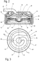
- 10 denotes a new temperature monitor which comprises a housing 12 which has a lower part 13 and a cover part 14 closing this.
- an insulating ring 15 with a T-shaped cross section is provided, which laterally rests on the inside against the lower part 13.
- a web 16 extends in the middle from the insulating ring 15, on which the cover part 14 rests at the top.
- a type of insulating cap 17 is arranged on the cover part 14 and is pressed onto the cover part 14 via a raised and crimped edge 18 of the lower part 13. In this way, the cover part 14 is insulated from the lower part 13 and is nevertheless firmly accommodated therein.
- a bimetallic switching mechanism 21 is arranged below the cover part 14 and comprises a spring washer 22 which carries a movable switching contact 23.
- the switching contact 23 is assigned a first fixed switching contact 24 on the underside of the cover part 14 and a second fixed switching contact 25 which is arranged on a carrier part 26 which is located in the lower part 13 below.
- a contact ring 27 is provided on the carrier part 26, on which the spring washer 23 rests with its outer edge 28.
- Above the spring washer 22 is a bimetallic snap disk 29, the edge of which lies between the web 16 and the cover part 14.
- the movable switch contact 23 is designed in the manner of a rivet 31 and holds the spring washer 22 and the bimetallic snap disk 29 together as follows:
- the rivet 31 has a neck 32 on which a ring 33 with a T-shaped cross section is arranged.
- the bimetallic snap disk 29 is held between an upper head 34 of the rivet 31 and a web 35 of the ring 33, while on the other side of the web 35 the spring washer 22 is held loosely between the web 35 and a washer 36 to which a lower head 37 of the rivet 31 connects.
- the bimetallic switching mechanism 21 is prefabricated from captive parts, so that it can be used as a whole in the lower part 13 during the assembly of the temperature monitor 10.
- an electrically conductive spacer ring 38 is arranged between the spring washer 22 and the bimetallic snap disk 29.
- a first terminal 41 of the temperature monitor in the form of a strand 42 is soldered to the cover part 14, while a second terminal 43 in the form of a strand 44 is connected to the lower part 13 via the edge 18.
- the temperature monitor 10 is shown at a temperature below the switching temperature of the bimetallic switching mechanism 21.
- the current flow through the temperature monitor 10 takes place from the first connection 41 via the cover part 14 and the first fixed switching contact 24 to the movable switching contact 23, from there via the spring washer 22 to the contact ring 27.
- the current reaches the contact ring 27 in FIG. 1 resistors, not shown, on the carrier part 26, which in turn is electrically conductively connected to the lower part 13, from where the current then flows to the second connection 43.
- the bimetallic switching mechanism switches into the switching position shown in FIG. 2. It can be seen that the bimetallic snap disk 29 is now supported with its edge on an outer lower edge 45 of the cover part 14, while the movable switching contact 23 now rests on the second fixed switching contact 25. It can also be seen that the spring washer 22 is also snapped over and now no longer has an electrically conductive connection to the contact ring 27. Rather, the spring washer 22 is now connected to the edge 45 of the cover part 14 via the spacer ring 38.
- the current flow through the temperature monitor 10 now takes place from the connection 41 via the cover part 14 and the edge 45 into the spring washer 22 and from there via the movable switching contact 23 to the fixed switching contact 25 on the carrier part 26, which is in the lower part 13 at the bottom 46 is arranged.
- Fig. 3 is a plan view of this carrier disc 26 is shown, which is preferably made of a ceramic disc 47, for. B. consists of Al 2 O 3 or another material.
- a thick-film resistor 48 is arranged on the ceramic disk 47 and extends in a spiral between the fixed switching contact 25 and a circular contact path 49 or an outer projection 50.
- the thick-film resistor 48 is provided with a via 51, which leads to the underside of the carrier part 26 and makes an electrically conductive contact with the bottom 46 of the lower part 13 there.
- the thick-film resistor 48 is divided into two resistors, namely a first heating resistor 43 between the fixed switching contact 25 and the through-contact 41 and a second heating resistor 54 between the through-contact 51 and the contact track 49.
- the via-contact 51 thus acts like one Type center tap 55, which divides the thick-film resistor 48 into a holding resistor R H provided for the self-holding function with the reference symbol 53 and a series resistor R V provided for the current sensitivity with the reference symbol 54.
- the series resistor R V is connected at its free end 56 to the projection 50, while the heating resistor R H is connected at its free end 47 to the switching contact 25.
- both heating resistors 53, 54 are formed on the carrier part 26, only this carrier part 26 has to be replaced if other resistance values for the heating resistors 53, 54 are desired.
- the carrier part 26 When using the carrier part 26, it is also possible to replace the heating resistor 53 with an insulating part 63 and / or the heating resistor 54 with a short-circuit part 64, so that the temperature monitor 10 has no self-holding function and / or no overcurrent sensitivity.
- a total of four differently equipped carrier parts 26 are therefore required to carry out all four variants of the temperature monitor 10, namely pure overtemperature protection, overtemperature protection with self-holding function, overtemperature protection with current sensitivity and To create overtemperature protection with self-holding function and current sensitivity.
- the assembly path and all other parts of the new temperature monitor 10 do not have to be changed.
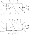
- FIG. 5 shows an equivalent circuit diagram similar to that in FIG. 4, but for a modified exemplary embodiment of the new temperature monitor 10. While the series resistor 54 is still formed on the bottom 46 in the lower part 13, the heating resistor 53 responsible for the self-holding function is now located on the cover part 14.
- the cover part may be provided from the inside with a thick-film resistor which extends between the edge 45 and the fixed switching contact 24.
- FIG. 6 shows in a cross section a so-called open temperature monitor 71, which has a plastic frame, indicated schematically at 72, as the supporting housing part.
- open temperature monitor 71 which has a plastic frame, indicated schematically at 72, as the supporting housing part.
- FIG. 6 comparable design features are identified with the reference symbols according to FIGS. 1 to 5 in order to facilitate understanding of the design.
- the two connections 41 and 43 are arranged on the frame 72 in the form of tabs which are suitably fastened to the frame 72.
- a switching tongue 73 made of bimetal which is clamped on one side and which is connected at its clamped end 74 to the first connection 41 via the second heating resistor 54.
- the switching tongue 73 carries the movable switching contact 23, to which the first switching contact 24 and the second switching contact 25 are assigned.
- the first switching contact 24 is connected directly to the second connection 43, while the second switching contact 25 is connected to the connection 43 via the first heating resistor 53.
- FIG. 7 shows an electrical equivalent circuit diagram of the temperature monitor 71 from FIG. 6. It can be seen that in this exemplary embodiment the series resistor R V is connected either alone or in series with the heating resistor R H between the two connections 41 and 43. The switch tongue 73 takes over the respective flowing current, whereby it either establishes a connection to the first switch contact 24 or to the second switch contact 25.
Landscapes
- Physics & Mathematics (AREA)
- Thermal Sciences (AREA)
- Thermally Actuated Switches (AREA)
- Glass Compositions (AREA)
- Control Of Combustion (AREA)
- Fire-Detection Mechanisms (AREA)
Applications Claiming Priority (2)
| Application Number | Priority Date | Filing Date | Title |
|---|---|---|---|
| DE19527254 | 1995-07-26 | ||
| DE19527254A DE19527254C2 (de) | 1995-07-26 | 1995-07-26 | Temperaturwächter |
Publications (3)
| Publication Number | Publication Date |
|---|---|
| EP0756301A2 true EP0756301A2 (fr) | 1997-01-29 |
| EP0756301A3 EP0756301A3 (fr) | 1998-05-27 |
| EP0756301B1 EP0756301B1 (fr) | 2001-12-19 |
Family
ID=7767808
Family Applications (1)
| Application Number | Title | Priority Date | Filing Date |
|---|---|---|---|
| EP96106744A Expired - Lifetime EP0756301B1 (fr) | 1995-07-26 | 1996-04-29 | Thermostat |
Country Status (4)
| Country | Link |
|---|---|
| US (1) | US5745022A (fr) |
| EP (1) | EP0756301B1 (fr) |
| AT (1) | ATE211300T1 (fr) |
| DE (2) | DE19527254C2 (fr) |
Cited By (6)
| Publication number | Priority date | Publication date | Assignee | Title |
|---|---|---|---|---|
| EP0915491A3 (fr) * | 1997-11-04 | 1999-12-08 | Marcel Hofsäss | Interrupteur avec un mécanisme de commutation sensible à la température |
| EP0920044A3 (fr) * | 1997-11-27 | 1999-12-08 | Marcel Hofsäss | Interrupteur avec un mécanisme de commutation sensible à la température |
| EP1720183A4 (fr) * | 2004-02-06 | 2007-06-20 | Tyco Electronics Raychem Kk | Interrupteur et dispositif utilisant l'interrupteur |
| CN102446656A (zh) * | 2010-09-30 | 2012-05-09 | 宝应电器厂 | 薄型温控器 |
| EP2874171A1 (fr) * | 2013-10-17 | 2015-05-20 | Thermik Gerätebau GmbH | Mécanisme de commutation variable avec la température |
| EP2846344A3 (fr) * | 2013-08-07 | 2015-05-20 | Thermik Gerätebau GmbH | Commutateur thermique |
Families Citing this family (17)
| Publication number | Priority date | Publication date | Assignee | Title |
|---|---|---|---|---|
| DE19545998C2 (de) * | 1995-12-09 | 1998-05-20 | Hofsaes Marcel | Schalter mit einem bei Übertemperatur schaltenden Schaltwerk |
| JPH11273519A (ja) * | 1998-03-25 | 1999-10-08 | Hosiden Corp | サーキットプロテクタとそれに用いる弾性熱応動板の製法 |
| US5936510A (en) * | 1998-05-22 | 1999-08-10 | Portage Electric Products, Inc. | Sealed case hold open thermostat |
| DE19827113C2 (de) * | 1998-06-18 | 2001-11-29 | Marcel Hofsaes | Temperaturabhängiger Schalter mit Stromübertragungsglied |
| US6498559B1 (en) * | 2000-05-24 | 2002-12-24 | Christopher Cornell | Creepless snap acting bimetallic switch having step adjacent its bimetallic element |
| JP2006092825A (ja) * | 2004-09-22 | 2006-04-06 | Fuji Denshi Kogyo Kk | 温度スイッチと温度スイッチの組立方法 |
| US7209337B2 (en) * | 2005-04-19 | 2007-04-24 | Remy International, Inc. | Electrical thermal overstress protection device |
| DE102009030353B3 (de) * | 2009-06-22 | 2010-12-02 | Hofsaess, Marcel P. | Kappe für einen temperaturabhängigen Schalter sowie Verfahren zur Fertigung eines temperaturabhängigen Schalters |
| DE102009039948A1 (de) * | 2009-08-27 | 2011-03-03 | Hofsaess, Marcel P. | Temperaturabhängiger Schalter |
| DE102012103306B3 (de) * | 2012-04-17 | 2013-04-25 | Thermik Gerätebau GmbH | Temperaturabhängiger Schalter mit Kontaktteil als Heizwiderstand |
| DE102013101392A1 (de) * | 2013-02-13 | 2014-08-14 | Thermik Gerätebau GmbH | Temperaturabhängiger Schalter |
| DE102013109291A1 (de) * | 2013-08-27 | 2015-03-05 | Thermik Gerätebau GmbH | Temperaturabhängiger Schalter mit am Rand eingeklemmter Schnappscheibe |
| CN110021505B (zh) * | 2019-05-19 | 2021-03-09 | 神州技测(上海)电子科技有限公司 | 电流过载保护器 |
| IT202100018779A1 (it) * | 2021-07-15 | 2023-01-15 | Miotti S R L | Dispositivo limitatore di temperatura |
| DE102023102304B4 (de) * | 2023-01-31 | 2024-08-08 | Marcel P. HOFSAESS | Temperaturabhängiges Schaltwerk und temperaturabhängiger Schalter |
| DE102023104836B3 (de) * | 2023-02-28 | 2024-05-16 | Marcel P. HOFSAESS | Temperaturabhängiges Schaltwerk und temperaturabhängiger Schalter |
| DE102023127597B3 (de) * | 2023-10-10 | 2025-02-13 | Marcel P. HOFSAESS | Temperaturabhängiger Schalter |
Family Cites Families (11)
| Publication number | Priority date | Publication date | Assignee | Title |
|---|---|---|---|---|
| BE452864A (fr) * | 1942-10-27 | |||
| NL168156B (nl) * | 1951-04-10 | Atlas Copco Ab | Draaislagwerktuig met omkeerbare slagrichting. | |
| FR1401964A (fr) * | 1963-07-19 | 1965-06-11 | Otter Controls Ltd | Interrupteur électrique sensible à la température |
| FR2138182B3 (fr) * | 1971-05-19 | 1973-05-11 | Dumesny Jacques | |
| US3667539A (en) * | 1971-05-24 | 1972-06-06 | Barber Colman Co | On-off time proportioning summer-winter thermostat and control system employing same |
| US5528448A (en) * | 1982-10-12 | 1996-06-18 | Leviton Manufacturing Co., Inc. | Heat flow detector for recessed incandescent fixtures |
| DE3601055A1 (de) * | 1986-01-16 | 1987-07-23 | Limitor Ag | Sicherheitsausschaltvorrichtung |
| DE3710387A1 (de) * | 1987-04-01 | 1988-10-13 | Thermostat & Schaltgeraetebau | Leistungssteuergeraet |
| DE4142716C2 (de) * | 1991-12-21 | 1997-01-16 | Microtherm Gmbh | Thermoschalter |
| DE9214940U1 (de) * | 1992-11-03 | 1992-12-17 | Thermik Geraetebau Gmbh, 7530 Pforzheim | Temperaturwächter |
| DE19604939C2 (de) * | 1996-02-10 | 1999-12-09 | Marcel Hofsaes | Schalter mit einem temperaturabhängigen Schaltwerk |
-
1995
- 1995-07-26 DE DE19527254A patent/DE19527254C2/de not_active Expired - Fee Related
-
1996
- 1996-04-29 DE DE59608480T patent/DE59608480D1/de not_active Expired - Fee Related
- 1996-04-29 EP EP96106744A patent/EP0756301B1/fr not_active Expired - Lifetime
- 1996-04-29 AT AT96106744T patent/ATE211300T1/de not_active IP Right Cessation
- 1996-07-26 US US08/686,853 patent/US5745022A/en not_active Expired - Fee Related
Cited By (9)
| Publication number | Priority date | Publication date | Assignee | Title |
|---|---|---|---|---|
| EP0915491A3 (fr) * | 1997-11-04 | 1999-12-08 | Marcel Hofsäss | Interrupteur avec un mécanisme de commutation sensible à la température |
| EP0920044A3 (fr) * | 1997-11-27 | 1999-12-08 | Marcel Hofsäss | Interrupteur avec un mécanisme de commutation sensible à la température |
| EP1720183A4 (fr) * | 2004-02-06 | 2007-06-20 | Tyco Electronics Raychem Kk | Interrupteur et dispositif utilisant l'interrupteur |
| US8395062B2 (en) | 2004-02-06 | 2013-03-12 | Tyco Electronics Raychem Kk | Switch and device using the switch |
| CN102446656A (zh) * | 2010-09-30 | 2012-05-09 | 宝应电器厂 | 薄型温控器 |
| EP2846344A3 (fr) * | 2013-08-07 | 2015-05-20 | Thermik Gerätebau GmbH | Commutateur thermique |
| US9691576B2 (en) | 2013-08-07 | 2017-06-27 | Thermik Geraetebau Gmbh | Temperature-dependent switch |
| EP2874171A1 (fr) * | 2013-10-17 | 2015-05-20 | Thermik Gerätebau GmbH | Mécanisme de commutation variable avec la température |
| US10256061B2 (en) | 2013-10-17 | 2019-04-09 | Thermik Geraetebau Gmbh | Temperature-dependent switching mechanism |
Also Published As
| Publication number | Publication date |
|---|---|
| US5745022A (en) | 1998-04-28 |
| DE59608480D1 (de) | 2002-01-31 |
| EP0756301A3 (fr) | 1998-05-27 |
| DE19527254C2 (de) | 2000-01-20 |
| ATE211300T1 (de) | 2002-01-15 |
| DE19527254A1 (de) | 1997-01-30 |
| EP0756301B1 (fr) | 2001-12-19 |
Similar Documents
| Publication | Publication Date | Title |
|---|---|---|
| EP0756301B1 (fr) | Thermostat | |
| EP0696810B1 (fr) | ContrÔleur de température | |
| EP0887826B1 (fr) | Interrupteur à commande thermique avec pont de contact | |
| EP0756302B1 (fr) | Thermostat de construction modulaire | |
| DE102008048554B3 (de) | Temperaturabhängiger Schalter | |
| DE3346298C2 (fr) | ||
| DE102011119632B3 (de) | Temperaturabhängiges Schaltwerk | |
| DE3122899A1 (de) | Temperaturschalter | |
| EP0920044B1 (fr) | Interrupteur avec un mécanisme de commutation sensible à la température | |
| EP0794546B1 (fr) | Interrupteur avec un mécanisme de commutation sensible à la température | |
| DE4142716A1 (de) | Thermoschalter | |
| DE19604939A1 (de) | Schalter mit einem temperaturabhängigen Schaltwerk | |
| DE102011119637B4 (de) | Temperaturabhängiger Schalter mit einem temperaturabhängigen Schaltwerk sowie Verfahren zum Herstellen eines solchen Schalters | |
| EP0740323B1 (fr) | Thermostat avec un dispositif interrupteur à bimétal commutant en cas de surchauffe | |
| EP0778596A2 (fr) | Interrupteur avec un mécanisme de commutation sensible à la température | |
| EP0678891B1 (fr) | Interrupteur dépendant du courant | |
| EP0858091B1 (fr) | Dispositif de protection d'un appareil | |
| DE19807288C2 (de) | Temperaturabhängiger Schalter | |
| DE19546004C2 (de) | Schalter mit einem bei Übertemperatur schaltenden Schaltwerk | |
| EP0778597B1 (fr) | Interrupteur avec un mécanisme de commutation actionné une température excessive | |
| EP0951041B1 (fr) | Interrupteur à commande thermique | |
| DE102023102302B3 (de) | Temperaturabhängiger Schalter | |
| DE3235649C2 (de) | Thermostatschalter | |
| DE2511214C2 (de) | Temperaturregeleinrichtung für elektrische Geräte | |
| DE102023127597B3 (de) | Temperaturabhängiger Schalter |
Legal Events
| Date | Code | Title | Description |
|---|---|---|---|
| PUAI | Public reference made under article 153(3) epc to a published international application that has entered the european phase |
Free format text: ORIGINAL CODE: 0009012 |
|
| AK | Designated contracting states |
Kind code of ref document: A2 Designated state(s): AT CH DE FR LI NL |
|
| PUAL | Search report despatched |
Free format text: ORIGINAL CODE: 0009013 |
|
| AK | Designated contracting states |
Kind code of ref document: A3 Designated state(s): AT CH DE FR LI NL |
|
| 17P | Request for examination filed |
Effective date: 19980618 |
|
| 17Q | First examination report despatched |
Effective date: 20000609 |
|
| GRAG | Despatch of communication of intention to grant |
Free format text: ORIGINAL CODE: EPIDOS AGRA |
|
| GRAG | Despatch of communication of intention to grant |
Free format text: ORIGINAL CODE: EPIDOS AGRA |
|
| GRAH | Despatch of communication of intention to grant a patent |
Free format text: ORIGINAL CODE: EPIDOS IGRA |
|
| GRAH | Despatch of communication of intention to grant a patent |
Free format text: ORIGINAL CODE: EPIDOS IGRA |
|
| GRAA | (expected) grant |
Free format text: ORIGINAL CODE: 0009210 |
|
| AK | Designated contracting states |
Kind code of ref document: B1 Designated state(s): AT CH DE FR LI NL |
|
| REF | Corresponds to: |
Ref document number: 211300 Country of ref document: AT Date of ref document: 20020115 Kind code of ref document: T |
|
| REG | Reference to a national code |
Ref country code: CH Ref legal event code: NV Representative=s name: TROESCH SCHEIDEGGER WERNER AG Ref country code: CH Ref legal event code: EP |
|
| REF | Corresponds to: |
Ref document number: 59608480 Country of ref document: DE Date of ref document: 20020131 |
|
| ET | Fr: translation filed | ||
| PLBE | No opposition filed within time limit |
Free format text: ORIGINAL CODE: 0009261 |
|
| STAA | Information on the status of an ep patent application or granted ep patent |
Free format text: STATUS: NO OPPOSITION FILED WITHIN TIME LIMIT |
|
| 26N | No opposition filed | ||
| PGFP | Annual fee paid to national office [announced via postgrant information from national office to epo] |
Ref country code: DE Payment date: 20050527 Year of fee payment: 10 |
|
| PGFP | Annual fee paid to national office [announced via postgrant information from national office to epo] |
Ref country code: FR Payment date: 20060411 Year of fee payment: 11 |
|
| PGFP | Annual fee paid to national office [announced via postgrant information from national office to epo] |
Ref country code: NL Payment date: 20060413 Year of fee payment: 11 |
|
| PGFP | Annual fee paid to national office [announced via postgrant information from national office to epo] |
Ref country code: CH Payment date: 20060418 Year of fee payment: 11 Ref country code: AT Payment date: 20060418 Year of fee payment: 11 |
|
| PG25 | Lapsed in a contracting state [announced via postgrant information from national office to epo] |
Ref country code: DE Free format text: LAPSE BECAUSE OF NON-PAYMENT OF DUE FEES Effective date: 20061101 |
|
| REG | Reference to a national code |
Ref country code: CH Ref legal event code: PL |
|
| NLV4 | Nl: lapsed or anulled due to non-payment of the annual fee |
Effective date: 20071101 |
|
| PG25 | Lapsed in a contracting state [announced via postgrant information from national office to epo] |
Ref country code: NL Free format text: LAPSE BECAUSE OF NON-PAYMENT OF DUE FEES Effective date: 20071101 |
|
| PG25 | Lapsed in a contracting state [announced via postgrant information from national office to epo] |
Ref country code: CH Free format text: LAPSE BECAUSE OF NON-PAYMENT OF DUE FEES Effective date: 20070430 Ref country code: LI Free format text: LAPSE BECAUSE OF NON-PAYMENT OF DUE FEES Effective date: 20070430 Ref country code: AT Free format text: LAPSE BECAUSE OF NON-PAYMENT OF DUE FEES Effective date: 20070429 |
|
| PG25 | Lapsed in a contracting state [announced via postgrant information from national office to epo] |
Ref country code: FR Free format text: LAPSE BECAUSE OF NON-PAYMENT OF DUE FEES Effective date: 20070430 |