EP0778596A2 - Interrupteur avec un mécanisme de commutation sensible à la température - Google Patents
Interrupteur avec un mécanisme de commutation sensible à la température Download PDFInfo
- Publication number
- EP0778596A2 EP0778596A2 EP96114995A EP96114995A EP0778596A2 EP 0778596 A2 EP0778596 A2 EP 0778596A2 EP 96114995 A EP96114995 A EP 96114995A EP 96114995 A EP96114995 A EP 96114995A EP 0778596 A2 EP0778596 A2 EP 0778596A2
- Authority
- EP
- European Patent Office
- Prior art keywords
- projection
- switch
- contact
- spring
- spring washer
- Prior art date
- Legal status (The legal status is an assumption and is not a legal conclusion. Google has not performed a legal analysis and makes no representation as to the accuracy of the status listed.)
- Granted
Links
Images

Classifications
-
- H—ELECTRICITY
- H01—ELECTRIC ELEMENTS
- H01H—ELECTRIC SWITCHES; RELAYS; SELECTORS; EMERGENCY PROTECTIVE DEVICES
- H01H37/00—Thermally-actuated switches
- H01H37/02—Details
- H01H37/32—Thermally-sensitive members
- H01H37/52—Thermally-sensitive members actuated due to deflection of bimetallic element
- H01H37/54—Thermally-sensitive members actuated due to deflection of bimetallic element wherein the bimetallic element is inherently snap acting
- H01H37/5427—Thermally-sensitive members actuated due to deflection of bimetallic element wherein the bimetallic element is inherently snap acting encapsulated in sealed miniaturised housing
-
- H—ELECTRICITY
- H01—ELECTRIC ELEMENTS
- H01H—ELECTRIC SWITCHES; RELAYS; SELECTORS; EMERGENCY PROTECTIVE DEVICES
- H01H37/00—Thermally-actuated switches
- H01H37/02—Details
- H01H37/32—Thermally-sensitive members
- H01H37/52—Thermally-sensitive members actuated due to deflection of bimetallic element
- H01H37/54—Thermally-sensitive members actuated due to deflection of bimetallic element wherein the bimetallic element is inherently snap acting
- H01H2037/5445—Thermally-sensitive members actuated due to deflection of bimetallic element wherein the bimetallic element is inherently snap acting with measures for avoiding slow break of contacts during the creep phase of the snap bimetal
-
- H—ELECTRICITY
- H01—ELECTRIC ELEMENTS
- H01H—ELECTRIC SWITCHES; RELAYS; SELECTORS; EMERGENCY PROTECTIVE DEVICES
- H01H37/00—Thermally-actuated switches
- H01H37/02—Details
- H01H37/32—Thermally-sensitive members
- H01H37/52—Thermally-sensitive members actuated due to deflection of bimetallic element
- H01H37/54—Thermally-sensitive members actuated due to deflection of bimetallic element wherein the bimetallic element is inherently snap acting
- H01H2037/5463—Thermally-sensitive members actuated due to deflection of bimetallic element wherein the bimetallic element is inherently snap acting the bimetallic snap element forming part of switched circuit
Definitions
- the present invention relates to a switch with a temperature-dependent switching mechanism, a housing which accommodates the switching mechanism and has a lower part and a cover part which closes the latter, and a first counter contact provided on the inside of the cover part and a second counter contact provided on the inside of the lower part, the switching mechanism being electrically conductive spring part, which in one of its switching positions is in contact with both the first and the second counter contact.
- the known switch is used to monitor the temperature of a device. For this purpose, it is connected in series with the device to be monitored via its external connections and arranged in such a way that the temperature of the device to be monitored influences the temperature of a bimetal part. If the switching temperature is exceeded, the switch mechanism opens the connection between the two external connections and the circuit above it is interrupted. If the temperature drops, the circuit is closed again, although this does not necessarily have to be the case; bistable temperature-dependent switches are also known.
- the known switch has a housing consisting of an electrically conductive lower part and an electrically conductive cover part which closes the latter, an insulating film being provided for insulation between the lower part and the cover part.
- An inwardly projecting area is formed on the cover part as a first counter contact.
- the switching mechanism has a spring washer, on which a movable contact is attached by a flanged edge, which comes into contact with the first mating contact.
- a bimetallic snap disk is placed over the spring washer, which is accommodated in the housing without forces below the switching temperature.
- the current flows through the conductive cover part, the first mating contact, the movable contact, the spring washer and the conductive lower part, on which the spring washer is supported, so that the inner bottom forms the second mating contact.
- the external connection is made directly by contacting the lower part and the cover part.
- the bimetal snap disk snaps and presses the spring washer with its movable contact away from the first counter contact.
- the mechanical assembly of the known switch is particularly complex because the contact must be attached to the spring washer via the flanged edge.
- a comparable switch is known from DE 37 10 672 A1.
- This so-called temperature monitor is designed to be self-retaining, so it includes a heating resistor connected in parallel to the bimetal switchgear, which is connected in series between the external connections when the switchgear is open and is heated up by the current flowing through it to the point that it heats the bimetal switchgear above it Switching temperature holds so that it does not return to the basic state.
- the high-resistance parallel resistor is integrated in the cover part, which consists either of insulating material or of an electrically conductive resistance material.
- the movable contact is loosely inserted in the spring washer and clamped between the spring washer and the bimetallic snap disk via a projecting annular shoulder.
- the movable contact is a turned part, which can only be produced with the appropriate material and manufacturing effort, so that it contributes significantly to the total cost of the known switches.
- this object is achieved in the switch mentioned at the outset in that a projection which points into the housing and which projects into an opening provided in the spring part at least in one switching position is provided on the first mating contact.
- the inventor of the present application has recognized that, surprisingly, the movable contact part on the spring part can be dispensed with, and that the required electrical contact between the spring part and the mating contact can be effected and / or promoted in that a projection is provided on the counter-contact, on which the spring washer sits, so to speak, with its opening.
- a projection is provided on the counter-contact, on which the spring washer sits, so to speak, with its opening.
- the projection ensures good, electrically conductive contact of the spring part with the first mating contact in the correct orientation.
- the new switch has a number of advantages.
- the manufacturing costs are reduced by the smaller number of components that can be found in the new switch, since the new mating contact replaces the previous movable contact part and the previous mating contact. Furthermore, it is no longer necessary to attach the contact part to the spring washer before or during the final assembly of the switch, so that this manufacturing step is omitted. Overall, this not only reduces the component costs, the costs for stockpiling and the number of components, but also the time required for the final assembly, which can now also take place automatically, thereby avoiding further rejects.
- Another advantage is that the number of contact resistances, ie the number of contact areas required, is reduced to the absolute minimum, since the contact resistance between the movable contact part used in the prior art and the spring washer is eliminated. The quality of the total contact resistance of the switch is thus improved, and the problems with the choice of material are also solved against the background of aging.
- the projection is made of an electrically conductive material or an electrically insulating material.
- the projection can be formed in one piece with the mating contact if it also consists of electrically conductive material. If, on the other hand, the projection is made of insulating material, it merely serves to guide the spring part relative to the mating contact, and it can preferably extend as a guide bolt to the bottom of the lower part.
- the projection made of electrically conductive material ensures even greater contact security between the spring part and the first mating contact, better guidance and centering of the spring part in the housing is possible in the case of the projection made of electrically insulating material in that the projection extends as a guide pin to the bottom of the lower part, but it does not lead to a short circuit due to its insulator ability.
- the spring part is held captively on the projection.
- the spring part is already attached to the projection attached to the cover part before the final assembly of the switch and then e.g. can be captively connected to the projection by flanging or welding. This also greatly simplifies the assembly of the new switch, since the fitting of a spring washer onto a projection is easier to automate than the insertion of a spring washer into a generally pot-like housing.
- the projection has a thickened head, over which the spring part can be pushed in a latching manner.
- the advantage here is that it is not absolutely necessary to ensure the captive hold after the spring part has been plugged onto the projection by additional measures such as flanging or welding. Rather, the spring washer is pushed over the thickened head, overcoming mechanical resistance, so that it snaps onto the projection. This measure also makes final assembly of the new switch much easier, since additional manufacturing steps can be saved.
- the spring part is a prestressed bimetallic snap disk, on the other hand it is preferred if the spring part is assigned a bimetal snap disk which is arranged with its opening on the projection.
- the switching mechanism is very simple, since the additional spring disk used in the prior art can be dispensed with.
- the bimetallic snap disk ensures both the electrical contact between the two mating contacts and the temperature-dependent switching of the rear derailleur.
- the spring part namely presses the bimetallic snap disk into the switch position in which, for example, the two mating contacts are connected to one another in an electrically conductive manner. If the bimetallic snap disc now heats up, this bimetallic snap disc is gradually deformed at its edge, that stands out from the ground. During this so-called creeping phase, however, the spring part ensures that the electrically conductive connection between the two mating contacts is retained. Only when the bimetallic snap disk snaps suddenly, that is to say jumps out of its convex shape into a concave shape, is the spring part lifted off the projection on the mating contact by the action of the bimetal snap disk.
- the cover part is made of electrically conductive material and the counter contact is deep-drawn from the material, the projection also preferably being deep-drawn from the material.
- both a spring washer and a plate spring or a spiral spring can be used as the spring part.
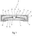
- a switch 10 is shown schematically in longitudinal section, which comprises a housing 11 in which a temperature-dependent switching mechanism 12 is arranged.
- the housing 11 comprises a lower part 14 and a cover part 15 closing it. Since both the lower part 14 and the cover part 15 consist of electrically conductive material, an insulating film 16 is arranged between them. In the assembled state shown in FIG. 1, the cover part is fastened to the lower part 14 by a flange 17 with the insulating film 16 interposed.
- the electrical connection of the switch 10 takes place, for example, in that strands or crimp connections are soldered to both the lower part 14 and the cover part 15. For the sake of clarity, these connections are not shown in the drawing.
- a first counter contact 21 is soldered or welded to its base part 22, so that there is an electrically conductive connection between the first counter contact 21 and the cover part 15.
- the first mating contact 21 furthermore has a projection 23 which points into the housing 11 and, in the exemplary embodiment shown in FIG. 1, is formed in one piece with the base part 22, that is to say likewise consists of electrically conductive material.
- the projection 23 it is also possible to manufacture the projection 23 from an electrically insulating material and to attach it to e.g. glue the base part 22.
- the switching mechanism 12 arranged in the housing 11 comprises a bimetallic snap disk 24 and a spring washer 25 arranged underneath it.
- the bimetal snap disk 24 and the spring washer 25 are arranged with their openings 26 and 27 on the projection 23, which is centered on the cover part 15 is provided so that the bimetallic snap disk 24 and the spring washer 25 are centered in the housing 11 by the selected arrangement.
- the spring washer 25 is supported with its edge 28 on the inner bottom 29 of the lower part 14, which acts as a second counter-contact 30.
- the switching state shown in Fig. 1 there is thus an electrically conductive connection of the cover part 12 via the first mating contact 21 and the spring washer 25 to the lower part 14, whereby the projection 23 ensures that the spring washer 25 and the bimetallic snap disc are provided with a centering effect 24 do not slip relative to the first mating contact 21; this increases the contact security.
- the bimetallic snap disc 24 bends upward with its edge 31 in FIG. 1, while the spring washer 25 continues for the electrical connection between the lower part 14 and the cover part 15 worries. If the switching temperature of the switching mechanism 12 is now exceeded, the bimetallic snap disk 24 suddenly snaps from its shown concave shape into a convex shape. It is then supported with its edge 31 on the insulating film 16 at the top and presses the spring washer 25 downward onto the bottom 29 of the lower part 14. The electrical contact with the first mating contact 21 is thus canceled, so that the switch 10 is, so to speak, open.
- a thickened head 32 is arranged on the projection 23, by means of which the bimetallic snap disk 24 and the spring washer 25 are held captively on the first mating contact 21 and thus on the cover part 15.
- This head can follow one hand the pushing of the bimetallic snap disk 24 and the spring washer 25 onto the projection 23 are produced by widening or flanging, but it can also be provided during the manufacture of the first mating contact 21. In the latter case, the head 32 is then dimensioned such that the openings 26 and 27 can be pushed over it under pressure, so that the bimetallic snap disk 24 and the spring washer 25 latch onto the projection 23, so to speak.
- the individual parts of the switching mechanism 12 can first be mounted on the cover part 15 before the cover part 15 is pushed onto the lower part 14.
- the order of the bimetallic snap disk 24 and the spring washer 25 is reversed compared to the exemplary embodiment from FIG. 1, the spring washer 25 lies above the bimetal snap disk 24.
- the bimetallic snap disc 24 lifts off with its edge 31 from the base 29 and presses the edge 28 upward against the force of the spring washer 25 against the insulating film 16.
- bimetallic snap disk 24 it is not absolutely necessary to provide a spring washer 25 in addition to the bimetallic snap disk 24.
- the latter can be dispensed with if the bimetallic snap disk 24 itself is designed as a prestressed spring part, so that it assumes the position shown in FIG. 2 below its switching temperature. Since the bimetallic snap disk 24 is generally also made of an electrically conductive material, it can thus itself ensure an electrical connection between the cover part 15 and the lower part 14.
- the arrangement of the bimetal snap disk 24 and the spring washer 25 again corresponds to the construction shown in FIG. 1.
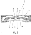
- a deep-drawn nose 34 is now provided on the cover part 15 as the first counter-contact 33, so that the first counter-contact 33 is, as it were, integral with the cover part 15.
- a guide pin 35 adjoins the nose 34 as a projection, which extends to the bottom 29 of the lower part 14.
- the function of the switch 10 shown in FIG. 3 corresponds exactly to that of the switch 10 shown in FIG. 1, but the cover part 15 is manufactured more simply.
- the guide pin 35 is made of insulating material and glued to the nose 34, for example. However, it is also possible to glue the guide pin 35 to the bottom 29, so that it already exerts its centering effect during the final assembly of the switch 10 when the bimetallic snap disk 24 and the spring washer 25 are inserted. If, however, the guide pin 25 is glued to the nose 34, the bimetallic snap disk 24 and the spring washer 25 are first pushed onto the guide pin 35 during the final assembly of the switch 10, before the lower part 14 is then pushed into the cover part 15 and flanged with it .
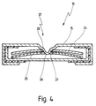
- a first mating contact 37 is provided, the nose 38 of which extends through the openings 26 and 27 in the bimetal snap disk 24 and the spring washer 25.
- the mating contact 37 and its nose 38 are formed integrally on the cover part 15 by deep drawing. The assembly of this switch 10 is thereby significantly simplified in the manner described above.
- the spring washer 25 can be dispensed with if the bimetallic snap disk 24 itself is designed as an electrically conductive spring part.
- the spring washer 25 can also be designed as a plate spring or as a spiral spring.
- the design as a spiral spring is possible here in that the projection formed on the first mating contact can serve as a guide and thus avoid lateral deflection of the spiral spring.
Landscapes
- Physics & Mathematics (AREA)
- Thermal Sciences (AREA)
- Thermally Actuated Switches (AREA)
- Slide Switches (AREA)
- Crystals, And After-Treatments Of Crystals (AREA)
- Oscillators With Electromechanical Resonators (AREA)
- Details Of Connecting Devices For Male And Female Coupling (AREA)
- Connector Housings Or Holding Contact Members (AREA)
Applications Claiming Priority (2)
| Application Number | Priority Date | Filing Date | Title |
|---|---|---|---|
| DE19545997A DE19545997C2 (de) | 1995-12-09 | 1995-12-09 | Schalter mit einem temperaturabhängigen Schaltwerk |
| DE19545997 | 1995-12-09 |
Publications (3)
| Publication Number | Publication Date |
|---|---|
| EP0778596A2 true EP0778596A2 (fr) | 1997-06-11 |
| EP0778596A3 EP0778596A3 (fr) | 1998-06-03 |
| EP0778596B1 EP0778596B1 (fr) | 2001-12-12 |
Family
ID=7779664
Family Applications (1)
| Application Number | Title | Priority Date | Filing Date |
|---|---|---|---|
| EP96114995A Expired - Lifetime EP0778596B1 (fr) | 1995-12-09 | 1996-09-19 | Interrupteur avec un mécanisme de commutation sensible à la température |
Country Status (5)
| Country | Link |
|---|---|
| US (1) | US5828286A (fr) |
| EP (1) | EP0778596B1 (fr) |
| AT (1) | ATE210888T1 (fr) |
| DE (2) | DE19545997C2 (fr) |
| ES (1) | ES2169781T3 (fr) |
Cited By (1)
| Publication number | Priority date | Publication date | Assignee | Title |
|---|---|---|---|---|
| EP2775495A1 (fr) * | 2013-03-04 | 2014-09-10 | Marcel P. Hofsaess | Commutateur thermosensible avec plaque isolante |
Families Citing this family (17)
| Publication number | Priority date | Publication date | Assignee | Title |
|---|---|---|---|---|
| WO1999001879A1 (fr) * | 1997-07-02 | 1999-01-14 | Siemens Aktiengesellschaft | Protection thermique pour la fixation sur un substrat de commutation |
| US20070173423A1 (en) * | 2004-06-29 | 2007-07-26 | Vermeer Robert C | Method and device for fragrancing and fabric treatment in a clothes dryer |
| JP2006092825A (ja) * | 2004-09-22 | 2006-04-06 | Fuji Denshi Kogyo Kk | 温度スイッチと温度スイッチの組立方法 |
| CN100446148C (zh) * | 2005-11-07 | 2008-12-24 | 徐佳义 | 手动复位温控器 |
| US7626484B2 (en) * | 2007-09-26 | 2009-12-01 | Honeywell International Inc. | Disc seat for thermal switch |
| DE102009030353B3 (de) * | 2009-06-22 | 2010-12-02 | Hofsaess, Marcel P. | Kappe für einen temperaturabhängigen Schalter sowie Verfahren zur Fertigung eines temperaturabhängigen Schalters |
| DE102009039948A1 (de) * | 2009-08-27 | 2011-03-03 | Hofsaess, Marcel P. | Temperaturabhängiger Schalter |
| US20130021132A1 (en) * | 2011-07-21 | 2013-01-24 | Honeywell International Inc. | Permanent one-shot thermostat |
| DE102011119632B3 (de) * | 2011-11-22 | 2013-04-11 | Marcel P. HOFSAESS | Temperaturabhängiges Schaltwerk |
| DE102011119637B4 (de) * | 2011-11-22 | 2013-06-06 | Marcel P. HOFSAESS | Temperaturabhängiger Schalter mit einem temperaturabhängigen Schaltwerk sowie Verfahren zum Herstellen eines solchen Schalters |
| DE102011122890A1 (de) | 2011-11-22 | 2013-05-23 | Marcel P. HOFSAESS | Temperaturabhängiges Schaltwerk |
| DE102019128367B4 (de) * | 2019-10-21 | 2021-06-10 | Marcel P. HOFSAESS | Temperaturabhängiger schalter |
| DE102022120446B3 (de) * | 2022-08-12 | 2023-11-30 | Marcel P. HOFSAESS | Temperaturabhängiger Schalter |
| DE102022120445B3 (de) * | 2022-08-12 | 2023-11-30 | Marcel P. HOFSAESS | Temperaturabhängiger Schalter |
| DE102023107383B3 (de) * | 2023-03-23 | 2024-05-29 | Marcel P. HOFSAESS | Aufnahmevorrichtung für einen temperaturabhängigen Schalter sowie Anordnung mit einer solchen Aufnahmevorrichtung |
| DE102023107382B3 (de) * | 2023-03-23 | 2024-05-29 | Marcel P. HOFSAESS | Aufnahmevorrichtung für einen temperaturabhängigen Schalter sowie Anordnung mit einer solchen Aufnahmevorrichtung |
| CN117533628B (zh) * | 2023-11-14 | 2025-08-08 | 常州音讯科技有限公司 | 一种控温自保护传热结构及保温容器 |
Family Cites Families (11)
| Publication number | Priority date | Publication date | Assignee | Title |
|---|---|---|---|---|
| US1687664A (en) * | 1926-06-23 | 1928-10-16 | Westinghouse Electric & Mfg Co | Thermostat |
| US2707738A (en) * | 1952-11-14 | 1955-05-03 | Siemens Ag | Midget thermostatic switch |
| US2785252A (en) * | 1955-04-04 | 1957-03-12 | Edward L Parr | Thermostatic switch for electric heaters |
| US2811611A (en) * | 1956-04-17 | 1957-10-29 | Odenwald Alfred | Small-type thermostat for preventing overheating in electrical apparatus |
| US3213250A (en) * | 1962-11-30 | 1965-10-19 | Texas Instruments Inc | Miniature snap acting thermostatic switch |
| CH400297A (de) * | 1963-03-22 | 1965-10-15 | Huber & Cie Ag J | Elektrischer, temperaturabhängiger Kleinstschalter |
| DE2143652B2 (de) * | 1971-09-01 | 1975-04-24 | Micro-Therm Gmbh, 7530 Pforzheim | Thermoschalter |
| DE2917482C2 (de) * | 1979-04-30 | 1982-11-25 | Peter 7530 Pforzheim Hofsäss | Übertemperaturschutzschalter |
| DE3122899C2 (de) * | 1981-06-10 | 1984-10-11 | Peter 7530 Pforzheim Hofsäss | Temperaturschalter |
| DE3710672C2 (de) * | 1987-03-31 | 1997-05-15 | Hofsaes Geb Zeitz Ulrika | Temperaturwächter mit einem Gehäuse |
| DE4337141C2 (de) * | 1993-10-30 | 1996-06-05 | Hofsaes Geb Zeitz Ulrika | Temperaturabhängiger Schalter |
-
1995
- 1995-12-09 DE DE19545997A patent/DE19545997C2/de not_active Expired - Fee Related
-
1996
- 1996-09-19 DE DE59608437T patent/DE59608437D1/de not_active Expired - Lifetime
- 1996-09-19 EP EP96114995A patent/EP0778596B1/fr not_active Expired - Lifetime
- 1996-09-19 AT AT96114995T patent/ATE210888T1/de not_active IP Right Cessation
- 1996-09-19 ES ES96114995T patent/ES2169781T3/es not_active Expired - Lifetime
- 1996-12-05 US US08/760,860 patent/US5828286A/en not_active Expired - Fee Related
Cited By (1)
| Publication number | Priority date | Publication date | Assignee | Title |
|---|---|---|---|---|
| EP2775495A1 (fr) * | 2013-03-04 | 2014-09-10 | Marcel P. Hofsaess | Commutateur thermosensible avec plaque isolante |
Also Published As
| Publication number | Publication date |
|---|---|
| ES2169781T3 (es) | 2002-07-16 |
| DE19545997A1 (de) | 1997-06-12 |
| ATE210888T1 (de) | 2001-12-15 |
| EP0778596A3 (fr) | 1998-06-03 |
| DE19545997C2 (de) | 1997-12-18 |
| DE59608437D1 (de) | 2002-01-24 |
| EP0778596B1 (fr) | 2001-12-12 |
| US5828286A (en) | 1998-10-27 |
Similar Documents
| Publication | Publication Date | Title |
|---|---|---|
| EP0778596B1 (fr) | Interrupteur avec un mécanisme de commutation sensible à la température | |
| EP0887826B1 (fr) | Interrupteur à commande thermique avec pont de contact | |
| DE102008048554B3 (de) | Temperaturabhängiger Schalter | |
| DE3122899C2 (de) | Temperaturschalter | |
| EP0721199B1 (fr) | Cummutateur dépendant de la température | |
| DE19521913C2 (de) | Doppelsicherheitsthermostat | |
| EP2874171B1 (fr) | Mécanisme de commutation variable avec la température | |
| DE102011119632B3 (de) | Temperaturabhängiges Schaltwerk | |
| DE19609577C2 (de) | Schalter mit einem temperaturabhängigen Schaltwerk | |
| DE19609310C2 (de) | Schalter mit einem temperaturabhängigen Schaltwerk | |
| WO2008113489A1 (fr) | Commutateur dépendant de la température et mécanisme de commutation prévu à cet effet | |
| DE19705154C2 (de) | Temperaturabhängiger Schalter mit einem Bimetall-Schaltwerk | |
| EP4258315A2 (fr) | Commutateur dépendant de la température | |
| EP0756301A2 (fr) | Thermostat | |
| DE102011119637B4 (de) | Temperaturabhängiger Schalter mit einem temperaturabhängigen Schaltwerk sowie Verfahren zum Herstellen eines solchen Schalters | |
| EP4325541A1 (fr) | Commutateur dépendant de la température | |
| EP0858091B1 (fr) | Dispositif de protection d'un appareil | |
| EP3660877B1 (fr) | Dispositif comprenant commutateur dépendant de la température et un capuchon de montage métallique | |
| DE19807288C2 (de) | Temperaturabhängiger Schalter | |
| DE19546004C2 (de) | Schalter mit einem bei Übertemperatur schaltenden Schaltwerk | |
| DE102023102304B4 (de) | Temperaturabhängiges Schaltwerk und temperaturabhängiger Schalter | |
| DE1159073B (de) | Bimetall-Schnappschalter mit Hand-Einschaltknopf | |
| DE102023005419A1 (de) | Temperaturabhängiges Schaltwerk und temperaturabhängiger Schalter | |
| DE102011122890A1 (de) | Temperaturabhängiges Schaltwerk | |
| DE102016101587A1 (de) | Mikrosignalschalter |
Legal Events
| Date | Code | Title | Description |
|---|---|---|---|
| PUAI | Public reference made under article 153(3) epc to a published international application that has entered the european phase |
Free format text: ORIGINAL CODE: 0009012 |
|
| AK | Designated contracting states |
Kind code of ref document: A2 Designated state(s): AT BE CH DE ES FR GB IT LI NL PT |
|
| PUAL | Search report despatched |
Free format text: ORIGINAL CODE: 0009013 |
|
| RAP1 | Party data changed (applicant data changed or rights of an application transferred) |
Owner name: HOFSAESS, MARCEL |
|
| AK | Designated contracting states |
Kind code of ref document: A3 Designated state(s): AT BE CH DE ES FR GB IT LI NL PT |
|
| 17P | Request for examination filed |
Effective date: 19980618 |
|
| GRAG | Despatch of communication of intention to grant |
Free format text: ORIGINAL CODE: EPIDOS AGRA |
|
| GRAG | Despatch of communication of intention to grant |
Free format text: ORIGINAL CODE: EPIDOS AGRA |
|
| GRAH | Despatch of communication of intention to grant a patent |
Free format text: ORIGINAL CODE: EPIDOS IGRA |
|
| 17Q | First examination report despatched |
Effective date: 20010207 |
|
| GRAH | Despatch of communication of intention to grant a patent |
Free format text: ORIGINAL CODE: EPIDOS IGRA |
|
| GRAA | (expected) grant |
Free format text: ORIGINAL CODE: 0009210 |
|
| AK | Designated contracting states |
Kind code of ref document: B1 Designated state(s): AT BE CH DE ES FR GB IT LI NL PT |
|
| REF | Corresponds to: |
Ref document number: 210888 Country of ref document: AT Date of ref document: 20011215 Kind code of ref document: T |
|
| REG | Reference to a national code |
Ref country code: CH Ref legal event code: NV Representative=s name: TROESCH SCHEIDEGGER WERNER AG Ref country code: CH Ref legal event code: EP |
|
| REG | Reference to a national code |
Ref country code: GB Ref legal event code: IF02 |
|
| REF | Corresponds to: |
Ref document number: 59608437 Country of ref document: DE Date of ref document: 20020124 |
|
| PG25 | Lapsed in a contracting state [announced via postgrant information from national office to epo] |
Ref country code: PT Free format text: LAPSE BECAUSE OF FAILURE TO SUBMIT A TRANSLATION OF THE DESCRIPTION OR TO PAY THE FEE WITHIN THE PRESCRIBED TIME-LIMIT Effective date: 20020312 |
|
| GBT | Gb: translation of ep patent filed (gb section 77(6)(a)/1977) |
Effective date: 20020313 |
|
| ET | Fr: translation filed | ||
| REG | Reference to a national code |
Ref country code: ES Ref legal event code: FG2A Ref document number: 2169781 Country of ref document: ES Kind code of ref document: T3 |
|
| PG25 | Lapsed in a contracting state [announced via postgrant information from national office to epo] |
Ref country code: BE Free format text: LAPSE BECAUSE OF NON-PAYMENT OF DUE FEES Effective date: 20020930 |
|
| PLBE | No opposition filed within time limit |
Free format text: ORIGINAL CODE: 0009261 |
|
| STAA | Information on the status of an ep patent application or granted ep patent |
Free format text: STATUS: NO OPPOSITION FILED WITHIN TIME LIMIT |
|
| 26N | No opposition filed | ||
| BERE | Be: lapsed |
Owner name: *HOFSASS MARCEL Effective date: 20020930 |
|
| PGFP | Annual fee paid to national office [announced via postgrant information from national office to epo] |
Ref country code: FR Payment date: 20050823 Year of fee payment: 10 |
|
| PGFP | Annual fee paid to national office [announced via postgrant information from national office to epo] |
Ref country code: GB Payment date: 20050912 Year of fee payment: 10 |
|
| PGFP | Annual fee paid to national office [announced via postgrant information from national office to epo] |
Ref country code: NL Payment date: 20050914 Year of fee payment: 10 |
|
| PGFP | Annual fee paid to national office [announced via postgrant information from national office to epo] |
Ref country code: ES Payment date: 20050920 Year of fee payment: 10 |
|
| PG25 | Lapsed in a contracting state [announced via postgrant information from national office to epo] |
Ref country code: NL Free format text: LAPSE BECAUSE OF NON-PAYMENT OF DUE FEES Effective date: 20070401 |
|
| GBPC | Gb: european patent ceased through non-payment of renewal fee |
Effective date: 20060919 |
|
| NLV4 | Nl: lapsed or anulled due to non-payment of the annual fee |
Effective date: 20070401 |
|
| REG | Reference to a national code |
Ref country code: FR Ref legal event code: ST Effective date: 20070531 |
|
| PG25 | Lapsed in a contracting state [announced via postgrant information from national office to epo] |
Ref country code: GB Free format text: LAPSE BECAUSE OF NON-PAYMENT OF DUE FEES Effective date: 20060919 |
|
| REG | Reference to a national code |
Ref country code: ES Ref legal event code: FD2A Effective date: 20060920 |
|
| PG25 | Lapsed in a contracting state [announced via postgrant information from national office to epo] |
Ref country code: ES Free format text: LAPSE BECAUSE OF NON-PAYMENT OF DUE FEES Effective date: 20060920 |
|
| PG25 | Lapsed in a contracting state [announced via postgrant information from national office to epo] |
Ref country code: FR Free format text: LAPSE BECAUSE OF NON-PAYMENT OF DUE FEES Effective date: 20061002 |
|
| PGFP | Annual fee paid to national office [announced via postgrant information from national office to epo] |
Ref country code: CH Payment date: 20080915 Year of fee payment: 13 |
|
| PGFP | Annual fee paid to national office [announced via postgrant information from national office to epo] |
Ref country code: IT Payment date: 20080925 Year of fee payment: 13 Ref country code: AT Payment date: 20080915 Year of fee payment: 13 |
|
| REG | Reference to a national code |
Ref country code: CH Ref legal event code: PL |
|
| PG25 | Lapsed in a contracting state [announced via postgrant information from national office to epo] |
Ref country code: AT Free format text: LAPSE BECAUSE OF NON-PAYMENT OF DUE FEES Effective date: 20090919 |
|
| PG25 | Lapsed in a contracting state [announced via postgrant information from national office to epo] |
Ref country code: LI Free format text: LAPSE BECAUSE OF NON-PAYMENT OF DUE FEES Effective date: 20090930 Ref country code: CH Free format text: LAPSE BECAUSE OF NON-PAYMENT OF DUE FEES Effective date: 20090930 |
|
| PGFP | Annual fee paid to national office [announced via postgrant information from national office to epo] |
Ref country code: DE Payment date: 20101023 Year of fee payment: 15 |
|
| PG25 | Lapsed in a contracting state [announced via postgrant information from national office to epo] |
Ref country code: IT Free format text: LAPSE BECAUSE OF NON-PAYMENT OF DUE FEES Effective date: 20090919 |
|
| PG25 | Lapsed in a contracting state [announced via postgrant information from national office to epo] |
Ref country code: DE Free format text: LAPSE BECAUSE OF NON-PAYMENT OF DUE FEES Effective date: 20130403 |
|
| REG | Reference to a national code |
Ref country code: DE Ref legal event code: R119 Ref document number: 59608437 Country of ref document: DE Effective date: 20130403 |