EP0756830A1 - Méthode pour l'autofabrication de cigarettes par le consommateur - Google Patents
Méthode pour l'autofabrication de cigarettes par le consommateur Download PDFInfo
- Publication number
- EP0756830A1 EP0756830A1 EP96111460A EP96111460A EP0756830A1 EP 0756830 A1 EP0756830 A1 EP 0756830A1 EP 96111460 A EP96111460 A EP 96111460A EP 96111460 A EP96111460 A EP 96111460A EP 0756830 A1 EP0756830 A1 EP 0756830A1
- Authority
- EP
- European Patent Office
- Prior art keywords
- tube
- tobacco
- transfer tube
- cigarette paper
- strand
- Prior art date
- Legal status (The legal status is an assumption and is not a legal conclusion. Google has not performed a legal analysis and makes no representation as to the accuracy of the status listed.)
- Granted
Links
- 235000019504 cigarettes Nutrition 0.000 title claims abstract description 148
- 238000004519 manufacturing process Methods 0.000 title claims description 31
- 241000208125 Nicotiana Species 0.000 claims abstract description 190
- 235000002637 Nicotiana tabacum Nutrition 0.000 claims abstract description 190
- 238000012546 transfer Methods 0.000 claims abstract description 137
- 238000003780 insertion Methods 0.000 claims abstract description 12
- 230000037431 insertion Effects 0.000 claims abstract description 12
- 239000002184 metal Substances 0.000 claims abstract description 11
- 229920003023 plastic Polymers 0.000 claims abstract description 6
- 239000004033 plastic Substances 0.000 claims abstract description 6
- 239000000463 material Substances 0.000 claims description 32
- 238000004806 packaging method and process Methods 0.000 claims description 31
- 230000000391 smoking effect Effects 0.000 claims description 15
- 238000012545 processing Methods 0.000 claims description 9
- 230000004323 axial length Effects 0.000 claims description 6
- 230000036541 health Effects 0.000 claims description 4
- 244000269722 Thea sinensis Species 0.000 claims description 3
- 238000004026 adhesive bonding Methods 0.000 claims description 3
- 239000012876 carrier material Substances 0.000 claims 1
- 239000000123 paper Substances 0.000 description 68
- 238000000034 method Methods 0.000 description 19
- 230000008569 process Effects 0.000 description 18
- 238000013461 design Methods 0.000 description 8
- 230000006835 compression Effects 0.000 description 5
- 238000007906 compression Methods 0.000 description 5
- 230000006399 behavior Effects 0.000 description 4
- 239000004820 Pressure-sensitive adhesive Substances 0.000 description 3
- 239000000853 adhesive Substances 0.000 description 3
- 230000001070 adhesive effect Effects 0.000 description 3
- 230000008901 benefit Effects 0.000 description 2
- 238000000926 separation method Methods 0.000 description 2
- 238000003860 storage Methods 0.000 description 2
- 239000002023 wood Substances 0.000 description 2
- 229910001369 Brass Inorganic materials 0.000 description 1
- 238000009825 accumulation Methods 0.000 description 1
- 239000012790 adhesive layer Substances 0.000 description 1
- 238000004873 anchoring Methods 0.000 description 1
- 230000015572 biosynthetic process Effects 0.000 description 1
- 239000010951 brass Substances 0.000 description 1
- 230000009172 bursting Effects 0.000 description 1
- 238000005056 compaction Methods 0.000 description 1
- 238000005520 cutting process Methods 0.000 description 1
- 238000011161 development Methods 0.000 description 1
- 230000018109 developmental process Effects 0.000 description 1
- 238000006073 displacement reaction Methods 0.000 description 1
- 230000002349 favourable effect Effects 0.000 description 1
- 238000002347 injection Methods 0.000 description 1
- 239000007924 injection Substances 0.000 description 1
- 238000009434 installation Methods 0.000 description 1
- 238000012986 modification Methods 0.000 description 1
- 230000004048 modification Effects 0.000 description 1
- 230000001151 other effect Effects 0.000 description 1
- 238000009417 prefabrication Methods 0.000 description 1
- 238000003825 pressing Methods 0.000 description 1
- 239000000779 smoke Substances 0.000 description 1
- 239000011343 solid material Substances 0.000 description 1
- 239000000243 solution Substances 0.000 description 1
- 229910001220 stainless steel Inorganic materials 0.000 description 1
- 239000010935 stainless steel Substances 0.000 description 1
- 230000007704 transition Effects 0.000 description 1
- 230000003313 weakening effect Effects 0.000 description 1
Images


Classifications
-
- A—HUMAN NECESSITIES
- A24—TOBACCO; CIGARS; CIGARETTES; SIMULATED SMOKING DEVICES; SMOKERS' REQUISITES
- A24C—MACHINES FOR MAKING CIGARS OR CIGARETTES
- A24C5/00—Making cigarettes; Making tipping materials for, or attaching filters or mouthpieces to, cigars or cigarettes
- A24C5/40—Hand-driven apparatus for making cigarettes
Definitions
- the invention relates to a system for the self-production of cigarettes by the consumer, as well as tobacco portion packs as an industrial prefabricated product and a device for use in the system.
- FIG. 11 of the present application drawing shows the tobacco cartridge made of tobacco rod or filling 63 and rod casing or casing 62, designated as a whole by 61, the associated filter cigarette paper tube 64, 65 and a sliding piston 66.
- the non-smoking of the prefabricated product (tobacco cartridge) 61 was due to a perforation 68 guaranteed in the strand casing and / or by appropriate material of the strand casing 62.
- the tobacco cartridge 61 was first introduced into the tobacco-receiving space 64 of the cigarette paper tube, and then the hands were freehand from the free end guided transfer plunger 66 inserted into the strand casing 62 and, while holding the strand casing by pressing the end of the casing casing against the surface of the transfer piston 66, the tobacco rod or the tobacco filling 63 is expelled from the casing 62, with successive displacement of the gradually filling cigarette tube.
- a tobacco-free section 67 could be provided within the strand casing 62 at one end of the tobacco cartridge.
- the advantage of this system is that the finished cigarette thus obtained corresponds completely to a conventional industrial finished cigarette with regard to the material nature of its components and the smoking behavior.
- a certain manual skill and practice is required for transferring the tobacco filling from the strand casing into the cigarette paper casing with the help of the free-hand guided plunger.
- the tobacco rod is transferred against the frictional resistance on the casing; the tobacco strand is slowed down by the tight-fitting wrapping. This can result in the tobacco rod not sliding smoothly. Sections of the tobacco filling that are compressed or too loose can result over the entire length of the filter sleeve; tobacco can be strongly compressed, which in extreme cases can lead to the sheathing and the filter sleeve bursting.
- German patent application P 44 04 274.4 proposes the wrapped tobacco strands first to be introduced into a tube in a device, and then to transfer the tobacco filling in the axial direction from the strand casings through a piston into an associated cigarette tube support tube coaxially aligned with the first tube, from which the tobacco filling is transferred by further piston feed into cigarette paper tubes which are fitted onto the cigarette tube support tube .
- the direct insertion of the wrapped tobacco rods into the cigarette paper tube is avoided, and the final transfer process of the tobacco rod takes place after removing the strand tube from a metal tube with only minimal friction of the tobacco filling on the inner wall of the tobacco tube.
- German patent application P 44 04 274 an industrial prefabricated product is already proposed, in which two or more tobacco portion units in the form of cigarette tobacco strands encased in a strand casing are combined to form a multi-portion package by connecting means, as a result of which the direct introduction of a tobacco portion into the Cigarette holder space of a cigarette paper tube is impossible, so the use of the single portion in the sense of the 'plug-in cigarettes' mentioned is excluded.
- a system is known from European Patent Specification 0 178 605 (LIEBICH), Fig. 12, in which the strand casing of the prefabricated, covered or coated tobacco rod is designed with a grip tab projecting radially from the closed circumference and with an axial predetermined tear point; an associated device is provided on a part of its length with a slot tube made of resiliently flexible material, in the slot of a short piston trapped in the tube is guided in a longitudinally displaceable manner; for self-manufacture of the cigarette, the coated tobacco rod is inserted into the slit tube, so that the pull tab is on the side protrudes through the slot; then pulling the tab laterally while breaking the predetermined tear seam pulls the strand casing laterally out of the slotted tube; a cigarette paper tube is then drawn onto the outside of the slotted tube, and finally the tobacco rod, which has been freed from the tube casing, is transferred through the short piston into the tobacco receiving space of the cigarette paper tube, with the cigarette paper tube being gradually pushed off the tube.
- the present invention is intended to create a system for the self-production of cigarettes by the consumer, in which the imperfections and inconveniences of the known systems are avoided and in a simple process and by means of a simple device with a small footprint, the production of completely evenly filled cigarettes without any particular manual Dexterity or practice is possible.
- the device has a transfer tube in the form of a thin, rigid metal or plastic tube with first and second ends, into which the tobacco portion package from one end is insertable and onto which the cigarette paper sleeve can be pushed from the first end, that means for removing the strand casing after insertion of the portio nsabpackung are provided in the transfer tube, and that the strand-like tobacco filling freed from the strand casing in the transfer tube by means of a piston which can be inserted into the rigid tube at the second end of the tube and can
- the means for removing the strand casing from the tobacco portion packaging inserted into the transfer pipe have an axially parallel slot at least over the part of the transfer pipe receiving the tobacco portion and, on the tobacco portion pack, a lateral pull tab protruding from the circumference of the strand casing, and optionally have a predetermined tear point extending over the axial length of the strand casing.
- the self-manufacture of a cigarette with the aid of the system according to the invention is free from the imperfections or intolerances of the known systems described above; it is completely simple, does not require any particular manual dexterity or practice and results in a cigarette which, in terms of the uniformity of the filling level, external appearance and in particular its smoking behavior, corresponds completely to a conventional industrially manufactured cigarette.
- the user To manufacture the cigarette, the user only needs to insert the wrapped tobacco portion package provided as an industrial prefabricated product into the transfer tube, to remove the strand casing from it, to pull a filter cigarette paper sleeve onto the outside of the transfer tube and then to simply push the long bulb through the transfer tube into the to transfer the exposed tobacco rod into the cigarette paper tube.
- the sliding takes place exclusively between the tobacco filling and the smooth inner wall of the transfer tube, so that no major and in particular fluctuating frictional resistances can be overcome and no relative Compression or congestion can occur, especially since the filter cigarette paper tube pushed onto the transfer tube gradually slides off smoothly with the transfer of the tobacco portion from the also smooth outer wall of the transfer tube without any significant friction or braking.
- the smooth operation of the transfer process is ensured in particular by the use of a long piston inserted from the other end of the transfer pipe, which is guided in the section of the transfer pipe free of tobacco from the beginning of the transfer process and continues in the transfer pipe during further advancement in the transfer pipe in the course of the transfer process remains reliably managed.
- the equipment required for the system according to the invention has an extremely simple, easy to manufacture and trouble-free design with very small dimensions, which are hardly larger than a disposable lighter, so that the equipment can be carried easily by the user if necessary.
- the device can have an elongated housing base body which also serves to hold the device, at one end of which the transfer tube is held and fastened such that a first end section of the transfer tube intended for receiving the filter cigarette paper sleeve is cantilevered from the mounting point along the elongated one Housing base body extends at a slight distance above this.
- the elongate housing base body extends axially over the cantilevered end of this first end portion of the transfer tube extends so that at the end of the transfer process the finished cigarette is supported and need not be particularly caught.
- the transfer tube can also have a second end section projecting from the mounting point in the opposite direction to the first end section, which serves to receive the tobacco portion package and is optionally slotted, the tobacco filling being moved from the second end section into the actual one with the aid of the piston Transfer section forming the first end portion and can be transferred into the filter cigarette paper tube.
- the filter cigarette paper tube and the tobacco portion pack are thus pushed onto or into the transfer tube from opposite sides.
- the first end section can be unslotted.
- the second end section can also not only be slotted but only be designed as an open trough with an approximately semicircular cross-section, into which the tobacco portion package is only inserted. This is particularly useful when a large number of tobacco portion packs are attached to a belt-shaped carrier.
- a knife element extends radially into the interior thereof, for example through a slot in the transfer tube, whereby this knife-shaped element slits the strand casing when the tobacco portion pack is inserted, so that it is easy to pull out.
- the desired tear point of the strand casing can be omitted.
- the non-smokability of the industrially prefabricated tobacco portion packs, as used for tax preferential treatment is necessary, can be ensured in several ways, if necessary also cumulatively: the material used for the wrapping of the tobacco rod as such can be unusable or non-flammable; the axial intended tear point of the strand casing, which may be provided, can expediently be embodied as a perforation, as a result of which independent wrapping of the wrapped tobacco portion is excluded; According to an advantageous embodiment, it can be provided that the strand casing of the tobacco portion pack is provided on the outside with a preferably strip or line-shaped material application made of a material which affects smoking, but is not harmful to health (for example a bitter tea); the portion package can be formed with a smaller diameter than the inside diameter of the transfer tube, so that when (improperly) inserting the coated tobacco portion package directly into a cigarette paper sleeve there would be a normal air-preventing air passage; alternatively, the portion pack could also be slightly larger in diameter than the inside diameter of the
- the tobacco portion package is formed as a double or two-portion package from two individual portions arranged in parallel at a distance from one another and connected to one another by a connecting part.
- the connecting part additionally prevents the individual tobacco portions from being directly introduced into a cigarette paper tube.
- the length of a tobacco portion package essentially corresponds to an integer part of the length of the filter cigarette tube, so that only the tobacco fillings of several tobacco portion packages are transferred into the filter cigarette paper tube completely fills them.
- the tobacco strands of a corresponding number of tobacco portion packs are successively transferred to a filter cigarette paper tube in order to completely fill it.
- the shorter length of the tobacco portion packs further facilitates the transfer process into the filter cigarette tube.
- the system according to the invention provides an optimal solution to the problem of self-manufacturing of cigarettes by the consumer using industrially prefabricated tobacco portion packs.
- FIGS. 1 to 3 the device in side view (FIG. 1), in plan view (FIG. 2) and the transfer piston forming part of the device (Fig. 3) show.
- the device designated as a whole by 1 has a housing 2 used for holding; overall, this is an approximately prismatic elongated body 2, which is provided on its upper side with a longitudinal trough 4 which extends essentially over the entire length.
- a mounting ring 3 is fastened in the trough, for example by gluing.
- a relatively rigid, thin-walled transfer tube 5 made of metal or plastic is embedded in the holding ring 3 (reference being made only to one metal tube in the following, although both materials and also other materials, such as wood, if appropriate) Can be used), which extends in parallel parallel to the trough part 4 and completely penetrates the mounting ring 3 and opens out at the outer (left in the drawing) end face 6.
- the transfer tube 5 is embedded in the mounting ring 3 over its entire axial extent and thereby firmly anchored; on the outer end face 6 opposite end face 7 of the retaining ring 3, the tube 5 is cantilevered with its main length and extends parallel to the trough 4 of the housing body 2, with which the transfer tube 5 is aligned along its projecting, unsupported length.
- the relative arrangement of transfer tube 5 and housing body 2 with longitudinal trough 4 is such that over the unsupported length of the transfer tube 5 between the trough 4 facing Underside and the trough surface adapted to the pipe curvature remains a distance d that is essentially constant over the length (of approximately 2 to 3 mm, compare the cross-sectional views of FIG. 4), which in the exemplary embodiment shown corresponds practically to the material thickness of the holding ring 3.
- the axial extent of the housing 2 is somewhat larger than that of the tube 5, so that the housing body 2 protrudes at its end 9 opposite the mounting ring 3 in the axial direction over the free end 10 of the transfer tube 5 by approximately 1 to 2 cm.
- the top of the transfer tube 5 is provided with an axial longitudinal slot 11, which extends over the entire unsupported length of the transfer tube 5 (and possibly also in the end of the transfer tube 5 embedded in the holding ring 3 can continue if this is preferable for manufacturing reasons).
- the slot 11 preferably has a width of approximately 1 mm.
- the transfer tube 5 is chamfered at 12 (in a side view) and rounded at 13 (a top view in FIG. 2) at the transition to the slot 11, in order to facilitate the introduction of the tobacco portion packaging (described below) and to facilitate the (also described below) pushing open the cigarette paper sleeve when using the device for self-manufacturing of the cigarette.
- this is provided with a nose 14, the function of which will be explained in the functional description of the device which follows below.
- FIG. 3 Another essential feature of the device according to the invention is the sliding or transfer piston shown in FIG. 3, which is designated as a whole by 15.
- the piston mainly consists of a cylindrical piston part 16 which takes up the main length and is provided at one end with a flange part 17 of larger diameter, which acts as an actuating member and serves as a stop.
- the piston 15 is inserted with its piston section 16 into the opening of the tube 5 opening at the outer end face 6 (as indicated by the arrow I) and successively advanced into the tube for the transfer of the tobacco portion described below Tube 5 in the cigarette receiving space of the cigarette paper tube.
- the piston is pushed through until the stop flange 17 abuts on the end face 6 of the holding ring 3. This completes the transfer of the tobacco portion.
- the piston When not in use, the piston is pulled out of the tube and inserted into the free end 12 of the transfer tube 5 from the opposite side according to arrow II. As soon as the actuation and stop button 17 arrives in the region of the trough 4, the piston is self-locked in its storage position in the device by a slight jamming.
- the housing 2 and the piston 15 can be made of any desired, sufficiently dimensionally stable material, in particular of plastic.
- the housing and the piston can be easily manufactured as injection molded parts.
- the housing and / or piston can also be made of wood.
- the tube 5 should have a high dimensional stability and torsional strength with the smallest possible wall thickness. Therefore, the manufacture of metal is provided for the tube 5, for example of stainless steel or hard brass.
- the wall thickness can be on the order of 0.2 to 0.3 mm.
- the outside diameter of the tube can, for example, be 6.8 mm in coordination with the inside diameter of the cigarette paper tube which has to be pulled onto the tube.
- the transfer tube 5 can be made, for example, from drawn seamless tube material with subsequent longitudinal slitting; alternatively and preferably it can be rolled from the corresponding sheet; in this case, the slot 11 then extends over the entire length of the transfer tube 5, ie also in the recessed in the mounting ring 3 Section.
- the inside (and outside) surface of the metal pipe is as smooth as possible, in order to ensure that the tobacco portion on the inside can be pushed out completely freely and smoothly (and that the cigarette paper tube is pushed on and stripped off just as smoothly on the outside of the pipe).
- the axial extent of the device is ultimately determined by the length of the industrially prefabricated tobacco portion pack and this by the usual length of the cigarette-receiving space of a filter cigarette paper tube.
- the total length of the piston can be approximately 11 cm, its usable piston length, which corresponds approximately to the unsupported length of the transfer tube 5, can be approximately 95 mm. Overall, this results in a total length of the order of magnitude of 12 to 13 cm for the device (which is shown essentially in natural size in the drawing), with a width of the order of magnitude of approximately 2 cm (top view) and a height (in Side view) of about 2 cm.
- the tobacco portion package designated as a whole by 20, consists of the inner tobacco rod 21 and a strand casing or casing 22 surrounding it.
- an axially parallel predetermined tear point is provided, for example in the form of a longitudinal perforation or another weakening seam.
- the strand casing is provided with one projecting outward from the circumference Trigger tab 24 provided.
- the pull tab 24 is made as a separate part in terms of manufacture, which is glued to a circumferential region of the strand cover 22, which is indicated by a relatively high tensile strength indicated at 25, and which is at a certain distance from the predetermined tear perforation 23 lies.
- the pull tab 24 is provided with a pressure-sensitive adhesive application 27 at its free end 26 on the production side and folded in the direction of arrow 28 into the position shown in dashed lines on the circumference of the portion pack and lightly wrapped at 26, 27 is releasably glued.
- a pressure-sensitive adhesive application 27 at its free end 26 on the production side and folded in the direction of arrow 28 into the position shown in dashed lines on the circumference of the portion pack and lightly wrapped at 26, 27 is releasably glued.
- the order 29 should consist of a material which would spoil the smoking pleasure if it was burned (contrary to the intended use), but is not harmful to health and does not impair the smell or other effects of the tobacco rod even if the prefabricated tobacco portions are stored for a long time.
- This material order can for example, a bitter tea in a suitable carrier.
- FIG. 6 shows a modified embodiment of the industrially prefabricated tobacco portion pack.
- the same or corresponding parts are designated by the same reference numerals as in FIG. 5.
- the main difference compared to the embodiment according to FIG. 5 is that the pull tab 24A is formed here in one piece with the casing 22 and simply represents an extension of the strand casing beyond the bonding area 25A in which the two ends of the strand casing are glued together.
- the predetermined tear point of the casing is again visible, and at 29 the material application to impair the enjoyment of smoking in the event of (improper) smoking of the prefabricated product as such.
- FIG. 7 shows a perspective view in schematic representation of a prefabricated tobacco portion pack of the type described.
- a further predetermined tear point 23A is provided, which runs in a plane perpendicular to the strand axis and extends over the entire circumference of the strand casing 22 including the pull tab 24 extends.
- This transverse predetermined tear point 23A can expediently be designed again as a perforation. This makes it easier to remove the casing when the tobacco portion pack in the device according to the invention is used as intended, as described below.
- This transverse perforation 23A enables the subdivision of the strand casing 22 into two axial sections 22A, 22B of approximately half the length, the lateral withdrawal of which is even easier and easier to accomplish through the slot of the transfer tube 5 of the device than the deduction of the strand casing 22 over its entire length in one act.
- FIG. 8 Another element for the manufacture of the cigarette is a conventional filter cigarette paper tube, as illustrated in FIG. 8.
- the sleeve designated as a whole by 30 has the actual sleeve section 31, which consists of conventional cigarette paper, and a filter section 32 attached to it.
- the procedure for producing the finished cigarette is as follows: First, the sliding piston 15 is pulled out of its (assumed) storage position in the transfer tube 5 (against the direction of arrow II in FIG. 2).
- the wrapped tobacco portion 20 (or 20A) is then removed after its pull tab 24 (24A) has been detached from the circumference of the strand casing 22 at the free end 26 while lifting the weak pressure-sensitive adhesive 27 and brought into the laterally protruding actuating position shown fully drawn in FIG. 5 , inserted into the transfer tube 5 in such a way that the laterally protruding pull tab 24 (24A) protrudes through the slot 11 to the outside.
- the above-mentioned nose 14 provided in the initial region of the slot causes a stripping of adhesive 25 which has been applied overly wide, so that the tab 24 is clearly lifted from the circumference of the strand casing along a straight line.
- the tobacco portion package 20 is fully inserted into the transfer tube 5, ie until the portion package stops with its inner end against the end wall 7 of the mounting ring 3 of the device.
- the tab 24 (24A) laterally, the casing of the portion package is torn open at the longitudinal perforation 23 forming a predetermined tear point and is pulled off to the outside.
- this process of pulling off the strand casing through the transverse perforation 23A can be made considerably easier.
- the strand casing can be practically divided into two halves 22A, 22B, which can be removed more easily one after the other than the strand casing over the entire length as a whole.
- the tobacco portion, freed from the casing, is now present in the smooth-walled transfer tube 5 for transfer into the cigarette paper tube, as the last step in the manufacturing process.
- the filter sleeve 30 (FIG. 8) with its sleeve section 31 is first pushed or pulled onto the tube 5 on the outside.
- the slight gap d (FIG. 4) between the outer wall of the tube 5 and the trough 4 ensures a certain linear guidance of the filter sleeve when it is plugged onto the tube 5 and prevents deformation of the thin paper of the filter sleeve.
- the filter sleeve 30 is pushed onto the transfer tube 5 until it stops, i.e. up to the stop of the filter section 32 against the outer free end 12 of the transfer tube 5.
- the sliding piston 15, 16 (in the direction of arrow I) is inserted from the opposite side (end face 6 of the mounting ring 3) and up to the stop of the flange 17 pushed through the end face 6. Since the tobacco only rests against the smooth inner surface of the tube 5, the tobacco slides easily and evenly into the filter sleeve at a low piston pressure, which is successively stripped from the smooth outer tube just as easily.
- the tobacco rod like a factory cigarette, cuts cleanly with the end of the filter sleeve. It is particularly advantageous that the cigarette in progress is supported by the certain protrusion of the housing body 2 over the tube end 10 of the tube 5 and therefore no longer needs to be caught against falling.
- the handling of the device is extremely simple. During the transfer process, the device is held on the housing 2 with one hand, while the other hand pushes the piston 15, 17 through the tube 5.
- the tobacco portion already freed from the strand casing is transferred directly from the (smooth-walled) transfer tube 5 into the successively filling filter sleeve, the sliding takes place exclusively between the tobacco filling and the smooth inner wall of the transfer tube, so that no larger and in particular fluctuating frictional resistances are to be overcome and no relative Compression or congestion can occur; thus a completely uniform filling is achieved over the entire length of the cigarette, without internal empty or hollow sections or compression and accumulation sections with corresponding stress on the cigarette paper tube, which in known designs could lead to the tube tearing.
- the industrially prefabricated tobacco portion pack can have several, preferably two tobacco portions connected to one another.
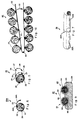
- FIG. 9 shows such a double-portion packaging in an intermediate stage of processing in a suitably adapted two-channel version of the device, specifically in cross section corresponding to a plane perpendicular to the longitudinal direction of the tobacco portions and the transfer pipes of the device.
- the double or two-portion package designated as a whole by 40, consists of two individual portions 41 and 42, which in the example shown are designed like the portion packages according to the embodiment according to FIG. 5, but can just as well correspond to the embodiment according to FIG. 6.
- FIG. 9 illustrates the preferred processing of such a double tobacco portion package in a device which corresponds to the device shown and described in FIGS.
- the double pack 40 can be expediently inserted into the two parallel slotted tubes through the relevant slits 11A in the undivided state, whereupon the connecting section 43 is separated along the predetermined tear point 44, which can be done by simply lifting, for example, by means of the piston rod guided underneath.
- the two half sections of the connecting part 43 then form the side pull tabs 24A, which can be used with their free ends for pulling off the strand casings laterally.
- the double package 40 could also be separated by opening the predetermined tear point 44 before insertion, and the separate single-portion packages could then be inserted into the two tubes 5A as described above.
- the tobacco portions are then transferred into the cigarette paper tubes by means of the piston 15 (FIG. 3).
- a double-piston unit can be provided, which can consist of two pistons 15, 16 parallel to one another according to FIG. 3, which can be connected to one another, for example, at the actuating end 17 at the predetermined distance.
- the transfer can also take place by means of two separate individual pistons, which are either pushed through at the same time or one after the other in time.
- the advantageous multiple, in particular double-portion packaging in the manner of the two-part packaging 40 in FIG. 9 can of course also be processed in a simple single-channel device according to FIGS. 1 to 3, either simply after prior separation of the double-portion packaging along the desired tear point 44 as 5 or 6, or alternatively also without prior separation, such that firstly a single portion, for example portion 41, is introduced into the slotted tube, namely by means of the connecting tab 43 which was initially obtained separately, then the strand casing of this introduced tobacco portion laterally is pulled out and this is further processed until the finished cigarette, while the remaining tobacco portion 42 of the double pack then next inserted and processed in the single channel device.
- the design of the industrial prefabricated product as a multiple tobacco portion pack also has the further advantage that it provides additional protection against (improper) use of the industrial prefabricated product in the manner known from the aforementioned patents as "plug-in cigarette", which is the desired tax recognition for the Favorable fine cut tariff supported by the tobacco tax.
- FIG. 10 Such an embodiment is illustrated in FIG. 10.
- a larger number of individual portion packs for example 10 individual portions, are combined on a common belt-shaped or band-shaped carrier 52 to form a packaging and packaging unit 50 in this embodiment in the form of a packaging unit designated as a whole by 50.
- the individual portions 51 can be of the type shown in FIG. 5 or FIG. 6 and are only indicated schematically in FIG. 10, the pull tabs 24 and 24A (from FIGS. 5 and 6) being omitted in FIG. 10 for the sake of clarity are.
- the individual portions 51 on the carrier belt 52 are parallel temporarily attached to each other by means of bonds 53 indicated at 53.
- the arrangement can be such that the carrier belt 52 is formed in the middle at 54 foldable (and possibly separable), so that the two belt halves thus formed by folding (indicated by the arrow 55 in Fig. 10) with their backs against each other.
- this multiple-portion pack can then be packaged, for example in a pack similar to that of an ordinary cigarette pack, or possibly also in a large pack with a round cross-section.
- the multi-portion packaging according to the type of FIG. 10 can not only be provided as a packaging and packaging unit but also be designed as a processing unit, analogously and in a further development of the double or double packaging illustrated in FIG. 9 and described above.
- the multiple pack shown in FIG. 10 could be designed as a six-pack, with three individual portions 51 on each of the two legs of the belt-like carrier 52 connected by the fold or kink 54.
- the processing of such a multiple pack could be carried out in a corresponding multi-channel version Equipment similar to the two-channel version in Fig. 9 take place.
- the three individual portions 51 could be processed on each of the two belt legs, the belt 52 taking over the function of the connecting part 43 in FIG.
- a support block 3 B consisting of solid material could be provided at the location corresponding to the support ring 3, in which the transfer tube 5 would be inserted with its anchoring end and in any manner, for example by gluing or could preferably also be connected to the housing base body 2 by a one-piece design. Accordingly, there are other possible modifications for the industrially prefabricated tobacco portion packs in addition to the designs shown in FIGS. 5 and 6, in particular with regard to the design and attachment of the pull tabs for the side pull.
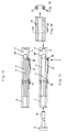
- a predetermined tear or perforation 22 of the filter cigarette paper tube 22, as shown in FIGS. 5 and 6, is not required if the embodiment of the device according to FIGS. 12 to 15 is used.
- the non-smoking casing 41, 42, 43 of the tobacco strand is cut open by a knife element 70 during insertion into the transfer tube 5.
- the knife element 70 can be moved resiliently via a leaf spring 71 through a further short slot in the transfer tube into its interior.
- the other end of the leaf spring 71 can be attached to the housing base body 2. Otherwise, this embodiment corresponds to the embodiment according to FIGS. 1 and 2.
- the embodiment of the tobacco portion pack shown in FIGS. 14 and 15 essentially corresponds to the embodiment according to FIG. 9, but without a predetermined tear in the form of a perforation.
- This longitudinal perforation must Production of the packages according to FIGS. 5, 6 and 9 run at a precisely defined distance from the adhesive seam of the flap. This is not necessary in the embodiment according to FIGS. 12 to 15.
- the cutting open of the wrapping is a significant relief when pulling out the empty packaging, without the effort required to form the predetermined tear point.
- the knife element 70 is firmly connected to the leaf spring 71. In the rest position, the tip of the knife element is outside the transfer tube 5, so that the piston is not touched when the tobacco is transferred. Before the double pack 41, 42 is inserted into the transfer tube 5, the leaf spring 71 must be pressed with the knife element attached and remains in this position until the slicing process has ended.
- a double pack 41, 42 can be selected with a length which is sufficient for filling a filter sleeve.
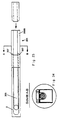
- FIGS. 16 to 18 largely corresponds to the embodiment according to FIGS. 1 to 3, wherein the device according to FIGS. 12 and 13 can also be used.
- the difference lies in the embodiment of the portion pack 22 according to FIG. 19, which is provided with an unusable, tear-resistant material strip 75 over its entire length and about 15 mm above it.
- the protruding material strip 75 is folded over and pressed onto the transfer tube holder 3 when the tobacco rod is transferred.
- the portion pack thus remains in a stable position.
- the empty casing is pulled out at the projecting material end 75.
- the transfer tube 5 need not be slotted. Furthermore, it is also possible here to fasten two or more transfer tubes parallel to one another on a common housing base body and accordingly to connect a number of portion packs to one another via their material strips 75.
- FIGS. 20 to 22 show an embodiment of the device with which two cigarettes can be produced by the consumer at the same time.
- respective first end portions 105A and second end portions 105B project in opposite directions from a case base 102.
- first end sections 105 serve to push on the filter cigarette paper tubes 30, while the second end sections serve to receive the portion packs 41, 42.
- first end sections 105A are unslotted, while the second end sections 105B are slotted similarly to the embodiments according to FIGS. 1 and 2 and serve to accommodate a double-portion package according to FIG. 9.
- portion packs according to FIG. 19 or portion packs free from a predetermined tear point could also be used here if the knife element according to FIG. 12 were used in the second end sections 105B.
- the length of the end sections 105B is selected as a function of the length of the portion packs 41, 42, 43, which, like the filter cigarette paper tubes 30, are shown in an exploded view in FIG. 20 in relation to the device 101. If portion packs with half or a third of the length of the filter cigarette paper tubes are used, the transfer process may be made considerably easier.
- the tobacco strands are transferred from the second end sections 105B into the first end sections 105A and thus into the filter cigarette paper sleeves pushed onto them with the aid of the double piston shown in particular in FIG. 22. This transfer process is also facilitated by the use of double portion packs of half or a third of the length of the filter cigarette paper tube.
- FIGS. 23 and 24 An embodiment of the device, which is particularly suitable for portion packs and which is suitable on a belt-shaped carrier, for example according to FIGS. 25, 26, 27 and 28, is shown in FIGS. 23 and 24. Also in this device, similar to the device according to FIGS. 20 to 22, the transfer tube 205 extends with its end sections 205A, 205B in opposite directions from a holder 203 of the device main body 2, the first end section 205A serving to receive the filter cigarette paper tubes while the end section 205B is designed to receive the portion packs attached to the belt-shaped carrier.
- the second end section 205B can not only be slotted but preferably trough-shaped with a substantially semicircular cross section, so that the tobacco portion packs attached to the belt-shaped carrier can be inserted into this trough and then transferred to the first end section 205A with the aid of a piston .
- the holder 203 can be provided with correspondingly shaped projections 207, which engage in respective notches or bevels on both sides of the tobacco portion packs 22 according to FIGS. 25 to 28.
- the belt-shaped carrier 252 continues to align the tobacco portion or partial portion packs 22 in the manner shown in FIG. 24 in their height with respect to the transfer tube 205.
- portion packs are also used for this or entire length of the filter cigarette paper tubes conceivable, or other even-numbered parts of this length.
- the belt-shaped carrier can consist, for example, of cardboard or relatively stiff paper, this material as such being non-smokable, although this is not possible anyway, in particular in the embodiment according to FIGS. 27 and 28 due to the short length of the tobacco portion packs.
- the individual portion packs can also be designed with a half or a third of the length of the filter cigarette paper tubes and thus cannot be smoked due to their short length.
- This information namely both the full length, half the length and the length of a third of the length of the filter cigarette paper tube are, of course, only general information, since at least the portion package having the full length of the cigarette paper tube is slightly longer than its tobacco-receiving space and the same naturally applies also for the tobacco portion packs with an integer part of the length of the filter cigarette paper tube, since a certain compression may occur when stuffing.
- FIGS. 29 and 30 A further embodiment is shown in FIGS. 29 and 30, in which three portion or partial portion packs are glued to a stiff core 253 located in the middle.
- This embodiment of the portion packs is particularly suitable for the equipment according to FIG. 23, but also for any other equipment.
- the portion or partial portion packs are not glued to one another, but are only connected to the rigid material core 253 via adhesive layers 254.
- An essential basic idea of the invention is the use of an industrial prefabricated product in the form of a tobacco portion strand encased in a strand casing, in a special design, in connection with a device which optionally supports a cantilevered body has slotted transfer pipe, into which the prefabricated product is inserted in such a way that the strand casing of the prefabricated product can be pulled off to the side or to the rear, so that the tobacco portion now lying in the transfer pipe without casing against the smooth inner wall with a long piston inserted from the end of the pipe into one can be transferred to the slotted transfer tube pulled cigarette paper tube.
Landscapes
- Packaging Of Annular Or Rod-Shaped Articles, Wearing Apparel, Cassettes, Or The Like (AREA)
- Manufacture Of Tobacco Products (AREA)
- Cigarettes, Filters, And Manufacturing Of Filters (AREA)
- Vending Machines For Individual Products (AREA)
Applications Claiming Priority (2)
| Application Number | Priority Date | Filing Date | Title |
|---|---|---|---|
| DE19528581 | 1995-08-03 | ||
| DE19528581A DE19528581B4 (de) | 1995-08-03 | 1995-08-03 | System zur Selbstverfertigung von Zigaretten durch den Verbraucher |
Publications (2)
| Publication Number | Publication Date |
|---|---|
| EP0756830A1 true EP0756830A1 (fr) | 1997-02-05 |
| EP0756830B1 EP0756830B1 (fr) | 2001-10-10 |
Family
ID=7768627
Family Applications (1)
| Application Number | Title | Priority Date | Filing Date |
|---|---|---|---|
| EP96111460A Revoked EP0756830B1 (fr) | 1995-08-03 | 1996-07-16 | Méthode pour l'autofabrication de cigarettes par le consommateur |
Country Status (6)
| Country | Link |
|---|---|
| EP (1) | EP0756830B1 (fr) |
| AT (1) | ATE206589T1 (fr) |
| CA (1) | CA2182651C (fr) |
| DE (2) | DE19528581B4 (fr) |
| DK (1) | DK0756830T3 (fr) |
| ES (1) | ES2164811T3 (fr) |
Cited By (5)
| Publication number | Priority date | Publication date | Assignee | Title |
|---|---|---|---|---|
| WO2002102177A1 (fr) * | 2001-06-18 | 2002-12-27 | Reemtsma Cigarettenfabriken Gmbh | Dispositif de bourrage permettant a un utilisateur de fabriquer ses propres cigarettes |
| WO2005104881A1 (fr) * | 2004-04-29 | 2005-11-10 | Reemtsma Cigarettenfabriken Gmbh | Paquet a quantite partielle de fine coupe et procede de fabrication de paquets a quantite partielle de fine coupe |
| EP1772068A1 (fr) * | 2005-10-06 | 2007-04-11 | Brinkmann Tabakfabriken GmbH | Emballage de portion de tabac et dispositif de bourrage |
| CN106036997A (zh) * | 2016-07-27 | 2016-10-26 | 王鼎兴 | 简易式手动卷烟器及其使用方法 |
| CN113519891A (zh) * | 2021-08-04 | 2021-10-22 | 胡阳兵 | 一种药膳香烟及其制备方法和设备 |
Families Citing this family (4)
| Publication number | Priority date | Publication date | Assignee | Title |
|---|---|---|---|---|
| USD595012S1 (en) | 2006-02-08 | 2009-06-23 | Philip Morris Usa Inc. | Combined tobacco block and wrapper |
| USD594742S1 (en) | 2006-02-08 | 2009-06-23 | Philip Morris Usa Inc. | Package |
| USD570540S1 (en) | 2006-11-22 | 2008-06-03 | Philip Morris Usa Inc. | Cigarette forming machine |
| US11375744B2 (en) | 2018-12-04 | 2022-07-05 | BBK Tobacco & Foods, LLP | Cone loading device and method therefor |
Citations (6)
| Publication number | Priority date | Publication date | Assignee | Title |
|---|---|---|---|---|
| CH192362A (de) * | 1936-12-16 | 1937-08-15 | Glaettli Emil | Vorrichtung, mittelst welcher Zigaretten von Hand hergestellt werden können. |
| DE3427480A1 (de) * | 1984-07-25 | 1986-02-06 | Helmut 8000 München Meinunger | Stopfvorrichtung fuer zigarettenhuelsen |
| EP0178605A1 (fr) * | 1984-10-16 | 1986-04-23 | Max Liebich | Méthode pour l'autofabrication de cigarettes par le consommateur |
| DE3914669A1 (de) * | 1989-05-03 | 1990-11-08 | Max Liebich | Vorrichtung und verfahren zur selbstverfertigung von zigaretten durch den verbraucher |
| EP0659352A1 (fr) * | 1993-12-23 | 1995-06-28 | Efka-Werke Fritz Kiehn GmbH | Procédé et dispositif pour remplir ou bourrer des tubes de papier à cigarette avec du tabac |
| DE4404274A1 (de) * | 1994-02-10 | 1995-08-17 | Max Liebich | System zur Selbstverfertigung von Zigaretten durch den Verbraucher |
Family Cites Families (3)
| Publication number | Priority date | Publication date | Assignee | Title |
|---|---|---|---|---|
| DE3337688A1 (de) * | 1983-03-28 | 1985-04-25 | Max 8370 Regen Liebich | Tabakerzeugnis zur selbstverfertigung von zigaretten durch den verbraucher |
| EP0212646B1 (fr) * | 1984-02-29 | 1990-07-18 | Efka-Werke Fritz Kiehn GmbH | Produit à base de tabac comportant une dose de tabac préparé à l'avance, entourée d'une enveloppe tubulaire en papier à cigarette, et procédé pour la préparation de ce produit |
| DE9303651U1 (de) * | 1993-03-12 | 1993-04-29 | Will, Raimond, 4300 Essen | Einführhilfe für Tabakröllchen in Zigarettenhülsen |
-
1995
- 1995-08-03 DE DE19528581A patent/DE19528581B4/de not_active Expired - Lifetime
-
1996
- 1996-07-16 ES ES96111460T patent/ES2164811T3/es not_active Expired - Lifetime
- 1996-07-16 DE DE59607869T patent/DE59607869D1/de not_active Revoked
- 1996-07-16 DK DK96111460T patent/DK0756830T3/da active
- 1996-07-16 AT AT96111460T patent/ATE206589T1/de not_active IP Right Cessation
- 1996-07-16 EP EP96111460A patent/EP0756830B1/fr not_active Revoked
- 1996-08-02 CA CA002182651A patent/CA2182651C/fr not_active Expired - Fee Related
Patent Citations (6)
| Publication number | Priority date | Publication date | Assignee | Title |
|---|---|---|---|---|
| CH192362A (de) * | 1936-12-16 | 1937-08-15 | Glaettli Emil | Vorrichtung, mittelst welcher Zigaretten von Hand hergestellt werden können. |
| DE3427480A1 (de) * | 1984-07-25 | 1986-02-06 | Helmut 8000 München Meinunger | Stopfvorrichtung fuer zigarettenhuelsen |
| EP0178605A1 (fr) * | 1984-10-16 | 1986-04-23 | Max Liebich | Méthode pour l'autofabrication de cigarettes par le consommateur |
| DE3914669A1 (de) * | 1989-05-03 | 1990-11-08 | Max Liebich | Vorrichtung und verfahren zur selbstverfertigung von zigaretten durch den verbraucher |
| EP0659352A1 (fr) * | 1993-12-23 | 1995-06-28 | Efka-Werke Fritz Kiehn GmbH | Procédé et dispositif pour remplir ou bourrer des tubes de papier à cigarette avec du tabac |
| DE4404274A1 (de) * | 1994-02-10 | 1995-08-17 | Max Liebich | System zur Selbstverfertigung von Zigaretten durch den Verbraucher |
Cited By (5)
| Publication number | Priority date | Publication date | Assignee | Title |
|---|---|---|---|---|
| WO2002102177A1 (fr) * | 2001-06-18 | 2002-12-27 | Reemtsma Cigarettenfabriken Gmbh | Dispositif de bourrage permettant a un utilisateur de fabriquer ses propres cigarettes |
| WO2005104881A1 (fr) * | 2004-04-29 | 2005-11-10 | Reemtsma Cigarettenfabriken Gmbh | Paquet a quantite partielle de fine coupe et procede de fabrication de paquets a quantite partielle de fine coupe |
| EP1772068A1 (fr) * | 2005-10-06 | 2007-04-11 | Brinkmann Tabakfabriken GmbH | Emballage de portion de tabac et dispositif de bourrage |
| CN106036997A (zh) * | 2016-07-27 | 2016-10-26 | 王鼎兴 | 简易式手动卷烟器及其使用方法 |
| CN113519891A (zh) * | 2021-08-04 | 2021-10-22 | 胡阳兵 | 一种药膳香烟及其制备方法和设备 |
Also Published As
| Publication number | Publication date |
|---|---|
| DK0756830T3 (da) | 2002-01-28 |
| DE59607869D1 (de) | 2001-11-15 |
| CA2182651A1 (fr) | 1997-02-04 |
| DE19528581B4 (de) | 2004-05-19 |
| EP0756830B1 (fr) | 2001-10-10 |
| ATE206589T1 (de) | 2001-10-15 |
| ES2164811T3 (es) | 2002-03-01 |
| CA2182651C (fr) | 2008-11-18 |
| DE19528581A1 (de) | 1997-02-06 |
Similar Documents
| Publication | Publication Date | Title |
|---|---|---|
| EP0155514B1 (fr) | Système pour la préparation d'une cigarette, procédé et dispositif en utilisant ce système | |
| DE4400192C2 (de) | Verfahren und Vorrichtung zum Füllen bzw. Stopfen von Zigarettenpapierhülsen mit Tabak | |
| EP0123150B1 (fr) | Système pret à l'emploi et procédé d'autofabrication de cigarettes par le consommateur | |
| EP0178605B1 (fr) | Méthode pour l'autofabrication de cigarettes par le consommateur | |
| EP0584805B1 (fr) | Produit à base de tabac pour l'autofabrication d'une cigarette ainsi que le dispositif de fabrication | |
| EP0275414B1 (fr) | Produit à base de tabac pour l'autofabrication d'une cigarette, notamment une cigarette à filtre | |
| DE3914669C2 (de) | Vorrichtung und Verfahren zur Selbstverfertigung von Zigaretten durch den Verbraucher | |
| DE69004297T2 (de) | Vorrichtung und Verfahren zum Herstellen von Zigaretten. | |
| DE3244906C2 (fr) | ||
| EP0756830B1 (fr) | Méthode pour l'autofabrication de cigarettes par le consommateur | |
| EP0647411B1 (fr) | Produit à base de tabac pour l'autofabrication de cigarettes, emballage ainsi que procédé de fabrication | |
| DE3711061C2 (fr) | ||
| DE19513010B4 (de) | Tabakerzeugnis für die Selbstverfertigung einer Zigarette, insbesondere Filter-Zigarette | |
| DE4404274A1 (de) | System zur Selbstverfertigung von Zigaretten durch den Verbraucher | |
| EP0659352B1 (fr) | Procédé et dispositif pour remplir ou bourrer des tubes de papier à cigarette avec du tabac | |
| WO2019141373A1 (fr) | Kit d'assemblage pour un article à fumer hnb, support de module pour un article à fumer hnb et article à fumer hnb | |
| DD245580A1 (de) | System und tabakerzeugnis zur selbstverfertigung von zigaretten durch den verbraucher | |
| EP0490098A1 (fr) | Produit à base de tabac pour l'autofabrication d'une cigarette, notamment une cigarette à filtre | |
| DE3410039A1 (de) | Tabakerzeugnis mit einem vorportionierten, in eine vorgefertigte zigarettenpapierhuelse ueberfuehrbaren tabakvorrat sowie verfahren und vorrichtung zur herstellung eines derartigen tabakerzeugnisses | |
| DE4207611A1 (de) | Tabakerzeugnis fuer die selbstverfertigung einer zigarette, insbesondere filter-zigarette, sowie verfahren zur selbstverfertigung einer zigarette | |
| DE4207769A1 (de) | Tabakerzeugnis fuer die selbstverfertigung einer zigarette, insbesondere filter-zigarette, sowie verfahren zur selbstverfertigung einer zigarette | |
| EP1347690A2 (fr) | Conditionnement pour fine coupe | |
| DE29507669U1 (de) | Tabakerzeugnis für die Selbstverfertigung einer Zigarette, insbesondere Filter-Zigarette, mit entfernbarer Stranghülle | |
| DE8817234U1 (de) | Tabakerzeugnis für die Selbstverfertigung einer Zigarette, insbesondere Filter-Zigarette | |
| DE8634390U1 (de) | Tabakerzeugnis für die Selbstverfertigung einer Zigarette, insbesondere Filter-Zigarette |
Legal Events
| Date | Code | Title | Description |
|---|---|---|---|
| PUAI | Public reference made under article 153(3) epc to a published international application that has entered the european phase |
Free format text: ORIGINAL CODE: 0009012 |
|
| AK | Designated contracting states |
Kind code of ref document: A1 Designated state(s): AT BE CH DE DK ES FR GB IT LI NL SE |
|
| 17P | Request for examination filed |
Effective date: 19971013 |
|
| RAP1 | Party data changed (applicant data changed or rights of an application transferred) |
Owner name: EFKA-WERKE FRITZ KIEHN GMBH |
|
| RIN1 | Information on inventor provided before grant (corrected) |
Inventor name: LIEBICH, MAX |
|
| 17Q | First examination report despatched |
Effective date: 19991022 |
|
| RAP1 | Party data changed (applicant data changed or rights of an application transferred) |
Owner name: THE HOUSE OF HEDGEWORTH INCORPORATED |
|
| RAP3 | Party data changed (applicant data changed or rights of an application transferred) |
Owner name: THE HOUSE OF EDGEWORTH INCORPORATED |
|
| GRAG | Despatch of communication of intention to grant |
Free format text: ORIGINAL CODE: EPIDOS AGRA |
|
| GRAG | Despatch of communication of intention to grant |
Free format text: ORIGINAL CODE: EPIDOS AGRA |
|
| GRAH | Despatch of communication of intention to grant a patent |
Free format text: ORIGINAL CODE: EPIDOS IGRA |
|
| GRAH | Despatch of communication of intention to grant a patent |
Free format text: ORIGINAL CODE: EPIDOS IGRA |
|
| GRAA | (expected) grant |
Free format text: ORIGINAL CODE: 0009210 |
|
| AK | Designated contracting states |
Kind code of ref document: B1 Designated state(s): AT BE CH DE DK ES FR GB IT LI NL SE |
|
| REF | Corresponds to: |
Ref document number: 206589 Country of ref document: AT Date of ref document: 20011015 Kind code of ref document: T |
|
| REG | Reference to a national code |
Ref country code: CH Ref legal event code: NV Representative=s name: RIEDERER HASLER & PARTNER PATENTANWAELTE AG Ref country code: CH Ref legal event code: EP |
|
| REF | Corresponds to: |
Ref document number: 59607869 Country of ref document: DE Date of ref document: 20011115 |
|
| REG | Reference to a national code |
Ref country code: GB Ref legal event code: IF02 |
|
| REG | Reference to a national code |
Ref country code: DK Ref legal event code: T3 |
|
| GBT | Gb: translation of ep patent filed (gb section 77(6)(a)/1977) |
Effective date: 20020114 |
|
| ET | Fr: translation filed | ||
| REG | Reference to a national code |
Ref country code: ES Ref legal event code: FG2A Ref document number: 2164811 Country of ref document: ES Kind code of ref document: T3 |
|
| PLBQ | Unpublished change to opponent data |
Free format text: ORIGINAL CODE: EPIDOS OPPO |
|
| PLBI | Opposition filed |
Free format text: ORIGINAL CODE: 0009260 |
|
| 26 | Opposition filed |
Opponent name: REEMTSMA CIGARETTENFABRIKEN GMBH Effective date: 20020708 |
|
| PLBF | Reply of patent proprietor to notice(s) of opposition |
Free format text: ORIGINAL CODE: EPIDOS OBSO |
|
| NLR1 | Nl: opposition has been filed with the epo |
Opponent name: REEMTSMA CIGARETTENFABRIKEN GMBH |
|
| PLBF | Reply of patent proprietor to notice(s) of opposition |
Free format text: ORIGINAL CODE: EPIDOS OBSO |
|
| PLBQ | Unpublished change to opponent data |
Free format text: ORIGINAL CODE: EPIDOS OPPO |
|
| PLAB | Opposition data, opponent's data or that of the opponent's representative modified |
Free format text: ORIGINAL CODE: 0009299OPPO |
|
| PLAB | Opposition data, opponent's data or that of the opponent's representative modified |
Free format text: ORIGINAL CODE: 0009299OPPO |
|
| PLBQ | Unpublished change to opponent data |
Free format text: ORIGINAL CODE: EPIDOS OPPO |
|
| R26 | Opposition filed (corrected) |
Opponent name: REEMTSMA CIGARETTENFABRIKEN GMBH Effective date: 20020708 |
|
| PLBF | Reply of patent proprietor to notice(s) of opposition |
Free format text: ORIGINAL CODE: EPIDOS OBSO |
|
| R26 | Opposition filed (corrected) |
Opponent name: REEMTSMA CIGARETTENFABRIKEN GMBH Effective date: 20020708 |
|
| NLR1 | Nl: opposition has been filed with the epo |
Opponent name: REEMTSMA CIGARETTENFABRIKEN GMBH |
|
| PGFP | Annual fee paid to national office [announced via postgrant information from national office to epo] |
Ref country code: NL Payment date: 20030630 Year of fee payment: 8 |
|
| PGFP | Annual fee paid to national office [announced via postgrant information from national office to epo] |
Ref country code: AT Payment date: 20030703 Year of fee payment: 8 |
|
| PGFP | Annual fee paid to national office [announced via postgrant information from national office to epo] |
Ref country code: GB Payment date: 20030704 Year of fee payment: 8 |
|
| PGFP | Annual fee paid to national office [announced via postgrant information from national office to epo] |
Ref country code: SE Payment date: 20030708 Year of fee payment: 8 Ref country code: CH Payment date: 20030708 Year of fee payment: 8 |
|
| PGFP | Annual fee paid to national office [announced via postgrant information from national office to epo] |
Ref country code: DK Payment date: 20030710 Year of fee payment: 8 Ref country code: DE Payment date: 20030710 Year of fee payment: 8 |
|
| PGFP | Annual fee paid to national office [announced via postgrant information from national office to epo] |
Ref country code: FR Payment date: 20030711 Year of fee payment: 8 |
|
| PGFP | Annual fee paid to national office [announced via postgrant information from national office to epo] |
Ref country code: ES Payment date: 20030718 Year of fee payment: 8 |
|
| PGFP | Annual fee paid to national office [announced via postgrant information from national office to epo] |
Ref country code: BE Payment date: 20030724 Year of fee payment: 8 |
|
| RDAF | Communication despatched that patent is revoked |
Free format text: ORIGINAL CODE: EPIDOSNREV1 |
|
| RDAG | Patent revoked |
Free format text: ORIGINAL CODE: 0009271 |
|
| STAA | Information on the status of an ep patent application or granted ep patent |
Free format text: STATUS: PATENT REVOKED |
|
| REG | Reference to a national code |
Ref country code: CH Ref legal event code: PL |
|
| 27W | Patent revoked |
Effective date: 20040527 |
|
| GBPR | Gb: patent revoked under art. 102 of the ep convention designating the uk as contracting state |
Free format text: 20040527 |
|
| REG | Reference to a national code |
Ref country code: SE Ref legal event code: ECNC |
|
| NLR2 | Nl: decision of opposition |
Effective date: 20040527 |