EP0757169A2 - Dispositif pour la régulation de paramètres de moteur, en particulier la puissance ou la vitesse de rotation d'un moteur à combustion interne - Google Patents
Dispositif pour la régulation de paramètres de moteur, en particulier la puissance ou la vitesse de rotation d'un moteur à combustion interne Download PDFInfo
- Publication number
- EP0757169A2 EP0757169A2 EP96111336A EP96111336A EP0757169A2 EP 0757169 A2 EP0757169 A2 EP 0757169A2 EP 96111336 A EP96111336 A EP 96111336A EP 96111336 A EP96111336 A EP 96111336A EP 0757169 A2 EP0757169 A2 EP 0757169A2
- Authority
- EP
- European Patent Office
- Prior art keywords
- adjustable
- internal combustion
- power
- combustion engine
- controller
- Prior art date
- Legal status (The legal status is an assumption and is not a legal conclusion. Google has not performed a legal analysis and makes no representation as to the accuracy of the status listed.)
- Granted
Links
- 238000002485 combustion reaction Methods 0.000 title claims description 26
- 230000001105 regulatory effect Effects 0.000 claims description 24
- 238000000034 method Methods 0.000 claims description 9
- 230000005540 biological transmission Effects 0.000 claims description 3
- 230000001276 controlling effect Effects 0.000 claims description 2
- 230000006698 induction Effects 0.000 abstract 2
- 239000007789 gas Substances 0.000 description 8
- 238000005086 pumping Methods 0.000 description 6
- 238000010586 diagram Methods 0.000 description 3
- 230000003321 amplification Effects 0.000 description 2
- 238000003199 nucleic acid amplification method Methods 0.000 description 2
- 230000002349 favourable effect Effects 0.000 description 1
- 238000005259 measurement Methods 0.000 description 1
- 239000000203 mixture Substances 0.000 description 1
Images

Classifications
-
- F—MECHANICAL ENGINEERING; LIGHTING; HEATING; WEAPONS; BLASTING
- F02—COMBUSTION ENGINES; HOT-GAS OR COMBUSTION-PRODUCT ENGINE PLANTS
- F02D—CONTROLLING COMBUSTION ENGINES
- F02D31/00—Use of speed-sensing governors to control combustion engines, not otherwise provided for
- F02D31/001—Electric control of rotation speed
- F02D31/002—Electric control of rotation speed controlling air supply
-
- F—MECHANICAL ENGINEERING; LIGHTING; HEATING; WEAPONS; BLASTING
- F02—COMBUSTION ENGINES; HOT-GAS OR COMBUSTION-PRODUCT ENGINE PLANTS
- F02D—CONTROLLING COMBUSTION ENGINES
- F02D41/00—Electrical control of supply of combustible mixture or its constituents
- F02D41/0002—Controlling intake air
- F02D41/0007—Controlling intake air for control of turbo-charged or super-charged engines
-
- F—MECHANICAL ENGINEERING; LIGHTING; HEATING; WEAPONS; BLASTING
- F02—COMBUSTION ENGINES; HOT-GAS OR COMBUSTION-PRODUCT ENGINE PLANTS
- F02B—INTERNAL-COMBUSTION PISTON ENGINES; COMBUSTION ENGINES IN GENERAL
- F02B37/00—Engines characterised by provision of pumps driven at least for part of the time by exhaust
- F02B37/12—Control of the pumps
- F02B37/16—Control of the pumps by bypassing charging air
-
- Y—GENERAL TAGGING OF NEW TECHNOLOGICAL DEVELOPMENTS; GENERAL TAGGING OF CROSS-SECTIONAL TECHNOLOGIES SPANNING OVER SEVERAL SECTIONS OF THE IPC; TECHNICAL SUBJECTS COVERED BY FORMER USPC CROSS-REFERENCE ART COLLECTIONS [XRACs] AND DIGESTS
- Y02—TECHNOLOGIES OR APPLICATIONS FOR MITIGATION OR ADAPTATION AGAINST CLIMATE CHANGE
- Y02T—CLIMATE CHANGE MITIGATION TECHNOLOGIES RELATED TO TRANSPORTATION
- Y02T10/00—Road transport of goods or passengers
- Y02T10/10—Internal combustion engine [ICE] based vehicles
- Y02T10/12—Improving ICE efficiencies
Definitions
- the invention relates to a device for regulating an engine size, in particular the power or the speed of an internal combustion engine, two or more adjustable devices being provided by means of which the engine size to be controlled can be influenced. Furthermore, the invention relates to a method for regulating an engine size, in particular the power or the speed of an internal combustion engine, in which the engine size to be controlled can be regulated via two or more adjustable devices.
- the object of the invention is to provide a simple device for regulating a motor size of an internal combustion engine, or a method suitable for this purpose, in order to provide a control which is simple in terms of structure and operation.
- the device according to the invention is characterized in that two or more separate controllers are provided, each of which controls one of the adjustable devices in dependence on the detected actual value of the motor size and on a predeterminable setpoint value, and that a switchover device is also provided, via which one can be selected the controller for regulating the associated adjustable device can be activated.
- the invention now provides for a separate simple controller to be provided for each of these adjustable devices.
- Each of these controllers can be simple and preferably only needs to control one of the adjustable devices.
- the adjustment of a single adjustable device on the engine is generally not sufficient.
- two or more such adjustable devices are therefore provided, each of which is regulated by a separate controller, a switchover device being provided which optionally activates one of the controllers to regulate the adjustable device associated with it. It is therefore only ever necessary for one of the regulators and the associated adjustable device to work, while the other adjustable devices are held in a fixed position.
- the motor size to be controlled can be regulated in different operating states, in particular at different powers or speeds, by adjusting a different adjustable device in accordance with the preferred method according to the invention, which considerably simplifies the regulation.
- This type of control not only has the advantage of a simple controller structure, but rather that adjustable device for control can be used in each operating state which exerts the best influence on the motor size to be controlled in this operating state.
- adjustable device for control can be used in each operating state which exerts the best influence on the motor size to be controlled in this operating state.
- the throttle valve for control, because in this area the throttle valve has a high influence on power or speed even with a small adjustment.
- the position of the throttle valve has little influence on these engine sizes at higher outputs and speeds and is therefore less suitable to regulate in this area.
- other adjustable devices on the internal combustion engine for example a controllable valve in the bypass line of a compressor, can be used to influence the motor size to be controlled more efficiently.
- the switchover device determines which controller together with the associated adjustment device is currently actively controlling, while the other adjustable devices are held in a fixed position.
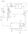
- an internal combustion engine is fed via a compressor 4, the compressed gas or gas mixture passing into the internal combustion engine M via a charge air cooler 5 and a throttle 6.
- the exhaust gases drive the turbine 7, which drives the compressor blades via a shaft 8 (exhaust gas turbocharger).
- a blow-by line 9 (return line) is provided parallel to the compressor 4, in which a preferably electrically controllable proportional valve 10 is arranged. By opening the valve 10, the gas flow through the compressor can be increased and the pressure after the compressor can be reduced, and thus pumping can be avoided.
- a device 11 which regulates two adjustable devices via control lines 12 and 13, by means of which the power to be regulated can be influenced.
- these adjustable devices are, on the one hand, the throttle valve 6 in the intake tract of the internal combustion engine M and, on the other hand, the controllable valve 10 in the blow-by line 9.
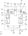
- the device 11 is supplied with the current actual value of the power P is via the input 14.
- a target value for the desired power P target is provided via the target value input 15.
- two separate controllers 16 and 17 are provided, each having a respective adjustable device 6 or 10 in dependence on the detected actual value of P is the power, and from a predeterminable desired value P of the power to regulate.
- a switching device 18 is provided, by means of which one of the controllers 16 or 17 can optionally be activated via the switching units 19 or 20 for regulating the adjusting device 6 or 10 associated with it.
- the switching device 18 is designed so that it only ever one of the two controllers 16 or 17 is activated, that is to say that the manipulated variable emitted by the respective controller actually feeds the adjustable device 6 or 10 via the switching unit 19 or 20.
- the internal combustion engine is in the low power range, in which the power control takes place via the throttle valve 6, that is, the controller 16 is active, while the controller 17 is inactive in the sense that its output signal is not that Valve 10 regulates. Rather, the valve 10 is connected via the switching unit 20 to a device 21 for emitting a presettable electrical actuating signal which, for example, emits a signal which the valve 10 in the blow-by line 9 opens fully in the low power range.
- Each controller 16 or 17 advantageously has a PID control unit 16a, 17a.
- a non-linear transmission element 22 or 23 is advantageously installed between the controller 16 or 17 and the associated adjustable device 6 or 10 in order to provide different gains in different power ranges. With this e.g. the fact that the throttle valve in the higher performance range hardly has any influence on the performance can be at least partially compensated for by increasing the degree of amplification in this performance range.
- the transmission element 22 has, for example, a characteristic curve inverse to the throttle valve characteristic, which converts the output signal U of the controller 16 with non-linear amplification into an output signal U ′, which is ultimately fed to the throttle valve 6.
- the switching device 18 is controlled via the lines 24 and 25 as a function of the position of the adjustable device 6, 10 or the electrical control signals supplied to these devices, in such a way that in a lower power range until the throttle valve 6 is fully opened regulation takes place via the throttle valve position while the valve 10 is fully open and that the switching unit 19 and 20 is switched over when the full throttle valve position is reached.
- the device 26 then holds the throttle valve in the fully open position by emitting a corresponding presettable electrical control signal, and the activated controller 17 closes the valve 10 with increasing desired output until finally when the full output is reached with the throttle valve 6 fully open, the valve 10 is full closed is.
- the switching device 18 could also in dependence on the detected actual value of P or setpoint P should be the controlled for regulating the motor, namely in the present embodiment, the power in such a way that the switching device is always enabled and only one of the two controllers 16 or 17th
- the method according to the invention which can be implemented, for example, with the devices described above, is characterized in that the motor size to be controlled is controlled in different operating states, in particular at different powers or speeds, by adjusting another adjustable device, only one at a time of the adjustable devices is adjusted by an associated controller while the other adjustable device (s) are held in a fixed position.
- controllable valve is arranged in a bypass line arranged parallel to a compressor
- the controllable valve is constantly fully open in the lower power or speed range of the internal combustion engine and the power or speed via the position the throttle valve is regulated in the intake tract, and that the throttle valve is constantly fully open in an upper power or speed range and the power or speed is regulated via the degree of opening of the controllable valve.
- a supercharged internal combustion engine can be regulated in terms of output in a simple manner, with the compressor characteristic curve diagram according to FIG. 3 always remaining below the so-called surge limit 27.
- the pressure ratio of the total pressures P 2tot / P 1tot is plotted against a normalized gas throughput V ⁇ 300 .
- Compressor characteristics of this type are supplied by the manufacturers of the compressors and in particular include the pumping limit 27, above which undesired pumping occurs in the intake tract of the internal combustion engine.
- the power can now be regulated via the throttle valve in the low power range according to line 28, while the valve 10 in the bypass line is fully open.
- the invention is of course not limited to the exemplary embodiments shown, for example other motor sizes, in particular the speed, can also be regulated in accordance with the ideas according to the invention. It is certainly favorable if the switching device 18 automatically selects the controller to be activated in each case. In principle, it would also be conceivable to switch over manually.
- the controller structure is particularly simple when each controller always controls only one adjustable device on the internal combustion engine. In principle, however, it would also be conceivable that one controller controls a set of a few adjustable devices of this type, while the other controller controls another adjustable device or also a set of adjustable devices.
Landscapes
- Engineering & Computer Science (AREA)
- Chemical & Material Sciences (AREA)
- Combustion & Propulsion (AREA)
- Mechanical Engineering (AREA)
- General Engineering & Computer Science (AREA)
- Output Control And Ontrol Of Special Type Engine (AREA)
- Supercharger (AREA)
- Combined Controls Of Internal Combustion Engines (AREA)
- Control Of Throttle Valves Provided In The Intake System Or In The Exhaust System (AREA)
Applications Claiming Priority (3)
| Application Number | Priority Date | Filing Date | Title |
|---|---|---|---|
| AT132895 | 1995-08-04 | ||
| AT132895 | 1995-08-04 | ||
| AT1328/95 | 1995-08-04 |
Publications (3)
| Publication Number | Publication Date |
|---|---|
| EP0757169A2 true EP0757169A2 (fr) | 1997-02-05 |
| EP0757169A3 EP0757169A3 (fr) | 1998-08-19 |
| EP0757169B1 EP0757169B1 (fr) | 2001-11-21 |
Family
ID=3511533
Family Applications (1)
| Application Number | Title | Priority Date | Filing Date |
|---|---|---|---|
| EP96111336A Expired - Lifetime EP0757169B1 (fr) | 1995-08-04 | 1996-07-13 | Dispositif pour la régulation de paramètres de moteur, en particulier la puissance ou la vitesse de rotation d'un moteur à combustion interne |
Country Status (4)
| Country | Link |
|---|---|
| US (1) | US5694899A (fr) |
| EP (1) | EP0757169B1 (fr) |
| AT (1) | ATE209299T1 (fr) |
| DE (1) | DE59608240D1 (fr) |
Cited By (9)
| Publication number | Priority date | Publication date | Assignee | Title |
|---|---|---|---|---|
| FR2749040A1 (fr) * | 1996-05-23 | 1997-11-28 | Daimler Benz Ag | Procede pour regler la pression dans le conduit d'aspiration d'un moteur a combustion interne et dispositif pour la mise en oeuvre du procede |
| EP1225330A2 (fr) | 2001-01-18 | 2002-07-24 | Jenbacher Aktiengesellschaft | Dispositif pour la régulation d'un moteur à allumage commandé |
| EP1609964A3 (fr) * | 2004-06-25 | 2007-05-16 | Robert Bosch Gmbh | Méthode pour le fonctionnement d'un moteur à combustion interne |
| US7287516B2 (en) | 2005-07-29 | 2007-10-30 | Caterpillar Inc. | Pump control system |
| EP1674709A3 (fr) * | 2004-12-23 | 2008-06-18 | GE Jenbacher GmbH & Co OHG | Moteur à combustion interne |
| EP2006514A3 (fr) * | 2007-06-20 | 2011-03-09 | GE Jenbacher GmbH & Co. OHG | Moteur à combustion interne fixe |
| EP2037099A3 (fr) * | 2007-09-13 | 2011-03-09 | GE Jenbacher GmbH & Co. OHG | Moteurs à combustion interne et dispositif de réglage de moteur |
| WO2011045272A1 (fr) * | 2009-10-14 | 2011-04-21 | Robert Bosch Gmbh | Moteur à combustion interne avec dispositif à suralimentation et procédé pour faire fonctionner un moteur à combustion |
| FR3007073A1 (fr) * | 2013-06-14 | 2014-12-19 | Renault Sa | Procede de pilotage d'un moteur a combustion interne suralimente et moteur suralimente associe |
Families Citing this family (17)
| Publication number | Priority date | Publication date | Assignee | Title |
|---|---|---|---|---|
| DE4434607A1 (de) * | 1994-09-28 | 1996-04-04 | Bosch Gmbh Robert | Schutzsystem für eine mit Aufladung betriebene Brennkraftmaschine |
| JP3521632B2 (ja) * | 1996-07-30 | 2004-04-19 | 日産自動車株式会社 | 内燃機関の制御装置 |
| US5949146A (en) * | 1997-07-02 | 1999-09-07 | Cummins Engine Company, Inc. | Control technique for a lean burning engine system |
| DE19739565B4 (de) * | 1997-09-10 | 2007-09-13 | Robert Bosch Gmbh | Verfahren und Vorrichtung zur Steuerung des Drehmoments einer Antriebseinheit eines Kraftfahrzeugs |
| US6408625B1 (en) | 1999-01-21 | 2002-06-25 | Cummins Engine Company, Inc. | Operating techniques for internal combustion engines |
| AT412805B (de) * | 2000-07-07 | 2005-07-25 | Jenbacher Ag | Verbrennungsmotor |
| US6434938B1 (en) * | 2001-07-16 | 2002-08-20 | International Engine Intellectual Property Company, L.L.C. | Control strategy for turbocharged engine having variable valve actuation apparatus |
| DE10225307A1 (de) * | 2002-06-07 | 2003-12-18 | Bosch Gmbh Robert | Verfahren und Vorrichtung zur Steuerung einer Brennkraftmaschine |
| US6701710B1 (en) * | 2002-09-11 | 2004-03-09 | Detroit Diesel Corporation | Turbocharged engine with turbocharger compressor recirculation valve |
| US6990814B2 (en) * | 2003-12-18 | 2006-01-31 | Caterpillar Inc. | Engine turbocharger control management system |
| FR2864579B1 (fr) * | 2003-12-24 | 2006-02-17 | Renault Sas | Moteur a combustion interne avec suralimentation pilotee et procede de pilotage de la suralimentation |
| DE102005005958A1 (de) * | 2005-02-10 | 2006-08-17 | Volkswagen Ag | Brennkraftmaschine mit Gasbetrieb |
| US7654086B2 (en) * | 2005-06-30 | 2010-02-02 | Caterpillar Inc. | Air induction system having bypass flow control |
| JP4717741B2 (ja) * | 2006-07-20 | 2011-07-06 | 本田技研工業株式会社 | エンジンの過給装置におけるエアバイパスバルブの故障検知装置 |
| JP4815294B2 (ja) * | 2006-07-25 | 2011-11-16 | 本田技研工業株式会社 | エンジンの過給装置における過給圧制御手段の故障検知装置 |
| DE102009032079A1 (de) * | 2009-07-07 | 2011-01-13 | Continental Automotive Gmbh | Verfahren und Vorrichtung zum Steuern einer aufgeladenen Brennkraftmaschine |
| DE102011013793A1 (de) * | 2011-03-12 | 2012-09-13 | Deutz Ag | Brennkraftmaschine und Verfahren zum Betreiben einer Brennkraftmaschine |
Family Cites Families (8)
| Publication number | Priority date | Publication date | Assignee | Title |
|---|---|---|---|---|
| JPS5818532A (ja) * | 1981-07-24 | 1983-02-03 | Suzuki Motor Co Ltd | 過給機付エンジンの吸気管制装置 |
| DE3135691A1 (de) * | 1981-09-09 | 1983-03-17 | Dr.Ing.H.C. F. Porsche Ag, 7000 Stuttgart | Lastregelung eines mit einem abgasturbolader aufgeladenen verbrennungsmotors |
| JPS58117321A (ja) * | 1981-12-31 | 1983-07-12 | Aisin Seiki Co Ltd | タ−ボチヤ−ジヤ制御システム |
| EP0089409B1 (fr) * | 1982-03-18 | 1989-03-29 | VDO Adolf Schindling AG | Système de coupure d'alimentation en carburant dans un moteur à combustion interne |
| JPS59103938A (ja) * | 1982-12-03 | 1984-06-15 | Fuji Heavy Ind Ltd | アイドル自動調速装置 |
| US4619232A (en) * | 1985-05-06 | 1986-10-28 | Ford Motor Company | Interactive idle speed control with a direct fuel control |
| JPS63223325A (ja) * | 1987-03-12 | 1988-09-16 | Fuji Heavy Ind Ltd | タ−ボチヤ−ジヤ付エンジンの吸気制御装置 |
| DE3939754A1 (de) * | 1989-12-01 | 1991-06-06 | Daimler Benz Ag | Verfahren zur regelung des druckes in der ansaugleitung vor den einlassventilen bei einer mittels eines abgasturboladers aufgeladenen luftverdichtenden einspritzbrennkraftmaschine |
-
1996
- 1996-07-13 AT AT96111336T patent/ATE209299T1/de active
- 1996-07-13 EP EP96111336A patent/EP0757169B1/fr not_active Expired - Lifetime
- 1996-07-13 DE DE59608240T patent/DE59608240D1/de not_active Expired - Lifetime
- 1996-08-02 US US08/691,570 patent/US5694899A/en not_active Expired - Lifetime
Non-Patent Citations (1)
| Title |
|---|
| None |
Cited By (12)
| Publication number | Priority date | Publication date | Assignee | Title |
|---|---|---|---|---|
| FR2749040A1 (fr) * | 1996-05-23 | 1997-11-28 | Daimler Benz Ag | Procede pour regler la pression dans le conduit d'aspiration d'un moteur a combustion interne et dispositif pour la mise en oeuvre du procede |
| US6058706A (en) * | 1996-05-23 | 2000-05-09 | Daimlerchrysler | Method and apparatus for regulating the pressure in a turbocharged internal combustion engine intake duct |
| US6244050B1 (en) * | 1996-05-23 | 2001-06-12 | Daimlerchrysler Ag | Apparatus for regulating the pressure in an internal combust ion engine intake ducts |
| EP1225330A2 (fr) | 2001-01-18 | 2002-07-24 | Jenbacher Aktiengesellschaft | Dispositif pour la régulation d'un moteur à allumage commandé |
| EP1609964A3 (fr) * | 2004-06-25 | 2007-05-16 | Robert Bosch Gmbh | Méthode pour le fonctionnement d'un moteur à combustion interne |
| EP1674709A3 (fr) * | 2004-12-23 | 2008-06-18 | GE Jenbacher GmbH & Co OHG | Moteur à combustion interne |
| US7287516B2 (en) | 2005-07-29 | 2007-10-30 | Caterpillar Inc. | Pump control system |
| EP2006514A3 (fr) * | 2007-06-20 | 2011-03-09 | GE Jenbacher GmbH & Co. OHG | Moteur à combustion interne fixe |
| EP2037099A3 (fr) * | 2007-09-13 | 2011-03-09 | GE Jenbacher GmbH & Co. OHG | Moteurs à combustion interne et dispositif de réglage de moteur |
| US8220265B2 (en) | 2007-09-13 | 2012-07-17 | Ge Jenbacher Gmbh & Co Ohg | Internal combustion engine with a variable geometry compressor |
| WO2011045272A1 (fr) * | 2009-10-14 | 2011-04-21 | Robert Bosch Gmbh | Moteur à combustion interne avec dispositif à suralimentation et procédé pour faire fonctionner un moteur à combustion |
| FR3007073A1 (fr) * | 2013-06-14 | 2014-12-19 | Renault Sa | Procede de pilotage d'un moteur a combustion interne suralimente et moteur suralimente associe |
Also Published As
| Publication number | Publication date |
|---|---|
| US5694899A (en) | 1997-12-09 |
| ATE209299T1 (de) | 2001-12-15 |
| EP0757169A3 (fr) | 1998-08-19 |
| DE59608240D1 (de) | 2002-01-03 |
| EP0757169B1 (fr) | 2001-11-21 |
Similar Documents
| Publication | Publication Date | Title |
|---|---|---|
| EP0757169B1 (fr) | Dispositif pour la régulation de paramètres de moteur, en particulier la puissance ou la vitesse de rotation d'un moteur à combustion interne | |
| DE69528013T2 (de) | Verwaltungssystem zur Turboladerregelung | |
| DE19711307C2 (de) | Elektronischer Regler für ein Turbolader-Wastegate | |
| DE10130471B4 (de) | Verfahren zur Steuerung eines Abgasrückführsystems | |
| DE102011007279A1 (de) | Ladeeinrichtung und zugehöriges Betriebsverfahren | |
| EP0930423A2 (fr) | Dispositif de réglage de la pression d'admission et de recirculation des gaz d'échappement d'un moteur à combustion interne, notamment d' un moteur diesel | |
| CH621855A5 (en) | Method for regulating turbo-compressors | |
| CH642718A5 (de) | Verfahren und einrichtung zum umsteuern von ventilen in der ersten stufe einer dampfturbine bei einem betriebsartwechsel. | |
| DE10127392A1 (de) | Verfahren und Vorrichtung zum Betreiben einer Brennkraftmaschine | |
| DE60215903T2 (de) | Verfahren zur Steuerung eines Abgasturboladers mit verstellbarer Turbinengeometrie | |
| DE4005466A1 (de) | Vorrichtung zum regeln der leerlaufdrehzahl einer brennkraftmaschine | |
| DE19754353C2 (de) | Gasmotor | |
| EP2006514B1 (fr) | Moteur à combustion interne fixe | |
| AT506182B1 (de) | Brennkraftmaschine sowie motorregeleinrichtung | |
| DE3212498A1 (de) | Steuerung fuer die zu- und abschaltung von abgasturboladern | |
| DE2414293C3 (de) | Last-Kompensationseinrichtung für aufgeladene Brennkraftmaschinen | |
| DE4221734C2 (de) | Aufladesystem für Brennkraftmaschinen | |
| AT5138U1 (de) | Verbrennungsmotor | |
| EP2282036B1 (fr) | Procédé et dispositif de commande d'un moteur à combustion interne dans un véhicule | |
| DE2545019A1 (de) | Einlaufregelung fuer luftatmende flugzeugtriebwerke, insbesondere von hochleistungsflugzeugen mit ueberschalltauglichkeit | |
| AT401088B (de) | Verfahren zum stufenlosen regeln der fördermenge von kolbenverdichtern und einrichtung zur durchführung des verfahrens | |
| EP0151805A2 (fr) | Dispositif de régulation électrique de la vitesse de ralenti d'un moteur à combustion | |
| DE3721908A1 (de) | Regelbarer turbolader | |
| WO2000052337A1 (fr) | Dispositif et procede permettant de regler un compresseur par etranglement du courant fluidique d'admission | |
| DE2848199A1 (de) | Regelung von luftzufuhr und brennstoffmenge einer hilfsbrennkammer |
Legal Events
| Date | Code | Title | Description |
|---|---|---|---|
| PUAI | Public reference made under article 153(3) epc to a published international application that has entered the european phase |
Free format text: ORIGINAL CODE: 0009012 |
|
| AK | Designated contracting states |
Kind code of ref document: A2 Designated state(s): AT CH DE FI FR GB IT LI NL SE |
|
| PUAL | Search report despatched |
Free format text: ORIGINAL CODE: 0009013 |
|
| AK | Designated contracting states |
Kind code of ref document: A3 Designated state(s): AT CH DE FI FR GB IT LI NL SE |
|
| 17P | Request for examination filed |
Effective date: 19981204 |
|
| RAP1 | Party data changed (applicant data changed or rights of an application transferred) |
Owner name: JENBACHER AKTIENGESELLSCHAFT |
|
| GRAG | Despatch of communication of intention to grant |
Free format text: ORIGINAL CODE: EPIDOS AGRA |
|
| GRAG | Despatch of communication of intention to grant |
Free format text: ORIGINAL CODE: EPIDOS AGRA |
|
| GRAH | Despatch of communication of intention to grant a patent |
Free format text: ORIGINAL CODE: EPIDOS IGRA |
|
| 17Q | First examination report despatched |
Effective date: 20010411 |
|
| GRAH | Despatch of communication of intention to grant a patent |
Free format text: ORIGINAL CODE: EPIDOS IGRA |
|
| GRAA | (expected) grant |
Free format text: ORIGINAL CODE: 0009210 |
|
| AK | Designated contracting states |
Kind code of ref document: B1 Designated state(s): AT CH DE FI FR GB IT LI NL SE |
|
| PG25 | Lapsed in a contracting state [announced via postgrant information from national office to epo] |
Ref country code: IT Free format text: LAPSE BECAUSE OF FAILURE TO SUBMIT A TRANSLATION OF THE DESCRIPTION OR TO PAY THE FEE WITHIN THE PRESCRIBED TIME-LIMIT;WARNING: LAPSES OF ITALIAN PATENTS WITH EFFECTIVE DATE BEFORE 2007 MAY HAVE OCCURRED AT ANY TIME BEFORE 2007. THE CORRECT EFFECTIVE DATE MAY BE DIFFERENT FROM THE ONE RECORDED. Effective date: 20011121 Ref country code: FI Free format text: LAPSE BECAUSE OF FAILURE TO SUBMIT A TRANSLATION OF THE DESCRIPTION OR TO PAY THE FEE WITHIN THE PRESCRIBED TIME-LIMIT Effective date: 20011121 |
|
| REF | Corresponds to: |
Ref document number: 209299 Country of ref document: AT Date of ref document: 20011215 Kind code of ref document: T |
|
| REG | Reference to a national code |
Ref country code: CH Ref legal event code: EP |
|
| REG | Reference to a national code |
Ref country code: GB Ref legal event code: IF02 |
|
| REF | Corresponds to: |
Ref document number: 59608240 Country of ref document: DE Date of ref document: 20020103 |
|
| PG25 | Lapsed in a contracting state [announced via postgrant information from national office to epo] |
Ref country code: SE Free format text: LAPSE BECAUSE OF FAILURE TO SUBMIT A TRANSLATION OF THE DESCRIPTION OR TO PAY THE FEE WITHIN THE PRESCRIBED TIME-LIMIT Effective date: 20020221 |
|
| GBT | Gb: translation of ep patent filed (gb section 77(6)(a)/1977) |
Effective date: 20020212 |
|
| PG25 | Lapsed in a contracting state [announced via postgrant information from national office to epo] |
Ref country code: LI Free format text: LAPSE BECAUSE OF NON-PAYMENT OF DUE FEES Effective date: 20020731 Ref country code: CH Free format text: LAPSE BECAUSE OF NON-PAYMENT OF DUE FEES Effective date: 20020731 |
|
| PLBE | No opposition filed within time limit |
Free format text: ORIGINAL CODE: 0009261 |
|
| STAA | Information on the status of an ep patent application or granted ep patent |
Free format text: STATUS: NO OPPOSITION FILED WITHIN TIME LIMIT |
|
| 26N | No opposition filed | ||
| REG | Reference to a national code |
Ref country code: CH Ref legal event code: PL |
|
| REG | Reference to a national code |
Ref country code: FR Ref legal event code: PLFP Year of fee payment: 20 |
|
| PGFP | Annual fee paid to national office [announced via postgrant information from national office to epo] |
Ref country code: NL Payment date: 20150726 Year of fee payment: 20 |
|
| PGFP | Annual fee paid to national office [announced via postgrant information from national office to epo] |
Ref country code: GB Payment date: 20150727 Year of fee payment: 20 Ref country code: DE Payment date: 20150729 Year of fee payment: 20 |
|
| PGFP | Annual fee paid to national office [announced via postgrant information from national office to epo] |
Ref country code: FR Payment date: 20150717 Year of fee payment: 20 Ref country code: AT Payment date: 20150619 Year of fee payment: 20 |
|
| REG | Reference to a national code |
Ref country code: DE Ref legal event code: R071 Ref document number: 59608240 Country of ref document: DE Ref country code: NL Ref legal event code: MK Effective date: 20160712 |
|
| REG | Reference to a national code |
Ref country code: GB Ref legal event code: PE20 Expiry date: 20160712 |
|
| REG | Reference to a national code |
Ref country code: AT Ref legal event code: MK07 Ref document number: 209299 Country of ref document: AT Kind code of ref document: T Effective date: 20160713 |
|
| PG25 | Lapsed in a contracting state [announced via postgrant information from national office to epo] |
Ref country code: GB Free format text: LAPSE BECAUSE OF EXPIRATION OF PROTECTION Effective date: 20160712 |