EP0757365A2 - Integrierter Transformator mit Empfangs- und Transformierungsfunfktionen - Google Patents
Integrierter Transformator mit Empfangs- und Transformierungsfunfktionen Download PDFInfo
- Publication number
- EP0757365A2 EP0757365A2 EP96300088A EP96300088A EP0757365A2 EP 0757365 A2 EP0757365 A2 EP 0757365A2 EP 96300088 A EP96300088 A EP 96300088A EP 96300088 A EP96300088 A EP 96300088A EP 0757365 A2 EP0757365 A2 EP 0757365A2
- Authority
- EP
- European Patent Office
- Prior art keywords
- transformer
- coil
- coils
- instrument
- molding material
- Prior art date
- Legal status (The legal status is an assumption and is not a legal conclusion. Google has not performed a legal analysis and makes no representation as to the accuracy of the status listed.)
- Withdrawn
Links
Images


Classifications
-
- H—ELECTRICITY
- H01—ELECTRIC ELEMENTS
- H01F—MAGNETS; INDUCTANCES; TRANSFORMERS; SELECTION OF MATERIALS FOR THEIR MAGNETIC PROPERTIES
- H01F27/00—Details of transformers or inductances, in general
- H01F27/02—Casings
- H01F27/022—Encapsulation
-
- H—ELECTRICITY
- H01—ELECTRIC ELEMENTS
- H01F—MAGNETS; INDUCTANCES; TRANSFORMERS; SELECTION OF MATERIALS FOR THEIR MAGNETIC PROPERTIES
- H01F38/00—Adaptations of transformers or inductances for specific applications or functions
- H01F38/20—Instruments transformers
Definitions
- the present invention relates to an integrated transformer having functions of receiving and transforming equipment and more particularly to an integrated transformer having functions of receiving and transforming equipment in which the coil of a power distribution transformer and the coils of a current transformer (CT) and an instrument transformer (PT) are electrically connected by electromagnetic induction, so that such coils are formed into an integral block by an insulating molding material and so that the transformer has the function of a receiving and transforming equipment.
- CT current transformer
- PT instrument transformer
- the respective devices are constructed as separate units and installed inside the cubicles; accordingly, the connecting parts of such devices and the cables themselves are exposed inside each cubicle.
- the respective devices are separately installed, work inside the cubicle is difficult, the interior space is not effectively utilized, the size of the equipment tends to be large, and the manufacturing costs are high.
- ammeters connected to the conventional current transformers are of a movable coil type in which a large current flows when the indicator needles of such ammeter are operated, thus causing electric shock accidents.
- the voltmeters connected to the instrument transformers are of a contact type, such voltmeters have likewise been a cause of electric shock accidents.
- insects, rats, etc. often penetrate into the interiors of the cubicles; in such cases, these insects, rats, etc. may contact exposed high-voltage parts, thus suffering an electric shock and causing deterioration of or damage to current transformers and instrument transformers.
- countermeasures against electric shock accidents suffered by workers and electric shock accidents caused by rats, etc. are insufficient. For example, several hundred electric shock accidents involving workers occur each year, and proposals for solving this problem have been awaited.
- the present invention was devised in light of the drawbacks inherent in the prior art described above and so as to eliminate these drawbacks in an appropriate manner.
- the object of the present invention is to provide an integrated transformer having functions of receiving and transforming equipment, which prevents the occurrence of electric shock accidents and which makes it possible to reduce the size of the equipment.
- the integrated transformer having functions of receiving and transforming equipment of the present invention is characterized in that the coils of a current transformer and an instrument transformer are installed in close proximity to the coil of a power distribution transformer so that these coils are electrically connected by electromagnetic induction, and the areas surrounding the coil of the power distribution transformer and the coils of the current transformer and instrument transformer are filled with an insulating molding material consisting of a synthetic resin such as an epoxy resin, etc., or a synthetic rubber such as a butyl rubber, etc., so that an integral block is formed.
- the integrated transformer having functions of receiving and transforming equipment which is provided by another invention of the present application is characterized in that:
- the integrated transformer having functions of receiving and transforming equipment which is provided by another invention of the present application is characterized in that:
- Figure 1 is an explanatory diagram which illustrates an integrated transformer having functions of receiving and transforming equipment, constituting a first embodiment of the present invention.
- Figure 2 is an explanatory diagram which illustrates the positional relationship between the current transformer and instrument transformer and the windings.
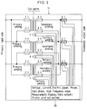
- Figure 3 is a circuit diagram, shown as one example, of the integrated transformer having functions of receiving and transforming equipment which constitutes the first embodiment.
- Figure 4 is an outside front view of an integrated transformer having functions of receiving and transforming equipment.
- Figure 5 is an explanatory diagram which illustrates an integrated transformer having functions of receiving and transforming equipment, constituting a second embodiment of the present invention.
- Figure 6 is an explanatory diagram which illustrates an integrated transformer having functions of receiving and transforming equipment, constituting a third embodiment of the present invention.
- Figure 7 is an explanatory diagram which illustrates an integrated transformer having functions of receiving and transforming equipment, constituting a fourth embodiment of the present invention.
- FIG. 1 is a schematic structural diagram of an integrated transformer having functions of receiving and transforming equipment, which constitutes a first embodiment of the present invention.
- the coil of a current transformer CT and the coil of an instrument transformer PT are installed, in a non-contact state, in close proximity to a coil 24 of a power distribution transformer Tr (single-phase or three-phase combination, etc.), so that these coils are electrically connected by electromagnetic induction.
- the areas surrounding the coil of the transformer Tr and the coils of the current transformer CT and instrument transformer PT are filled with an insulating molding material 12 so that an integral block is formed. In this way, a transformer Tr which has the function of receiving and transforming equipment with an integrated current transformer CT and instrument transformer PT is constructed.
- the coil 24 of the transformer Tr and the coils of the current transformer CT and instrument transformer PT are molded into an integral unit by means of the insulating molding material 12 so that the high-voltage portions of such coils are not exposed to the outside.
- this transformer Tr which functions as an integrated type receiving and transforming equipment is installed inside a cubicle 10 which is used as an outer covering.
- a synthetic resin such as an epoxy resin or polyester resin, etc., or a synthetic rubber such as a butyl or ethylene-propylene rubber, etc., may be appropriately used as the insulating molding material 12.
- such a molding may be performed so that the magnetic fields of the coils do not extend to the outside of the molding or so that the magnetic fields can extend to the outside of the molding.
- Figure 2 shows the relationship between the coil 24 of the transformer Tr and the coils of the digital type current transformer CT and instrument transformer PT in schematic form; and it is designed so that the current is measured by an ammeter A, with the coil of the current transformer CT being caused to face one winding 19 of the coil 24 of the transformer Tr in a non-contact state (see Figure 2(a)) and so that, as shown in Figure 2(b), the voltage is measured by a voltmeter V, with the coil of the instrument transformer PT being caused to face one winding 19 of the coil 24 of the transformer Tr in a non-contact state.
- the voltage applied to one winding 19 of the coil 24 is extremely small, by installing the coils of the current transformer CT and instrument transformer PT in a non-contact state at an extremely small distance from the winding 19, the current flowing through the current transformer CT and instrument transformer PT can be reduced to an extremely small value (e. g., 0.1 mA to 0.01 mA). As a result, the generation of heat can be minimized, and safety can be improved. A reduction in cost can also be achieved. Meanwhile, the ammeter A and voltmeter V are integrally incorporated into the interior portion of the insulating molding material 12.
- the current transformer CT and instrument transformer PT are manufactured as an integral unit with the transformer Tr, so that no electric-charged parts are exposed to the outside of the transformer unit. Moreover, it is possible to install the ammeter A connected to the current transformer CT and the voltmeter V connected to the instrument transformer PT on the outside of the insulating molding material 12.
- Figure 3 shows one example of a circuit diagram of the transformer Tr.
- measurement in the instrument transformer PT is accomplished by electromagnetic induction between the coil 24 (secondary winding) of the transformer Tr and the coil (tertiary winding) of the instrument transformer PT.
- measurement in the current transformer CT is accomplished by electromagnetic induction between the coil 24 (secondary winding) of the transformer Tr and the coil of the current transformer CT.
- the coil 24 of the transformer Tr and the coils of the current transformer CT and instrument transformer PT are electrically connected in a non-contact state by electromagnetic induction; accordingly, the currents flowing through these electrical measuring instruments can be extremely small, and a conspicuous reduction in the size of the transformer can be achieved.
- the current transformer CT and instrument transformer PT are connected to a measurement/display/data output/printer print out section 26 which is provided inside the coil.
- this output section 26 voltage, current, electric power, phase, open phase and high frequency values are digitally displayed, and if necessary, these values can be printed out.
- the output section 26 is equipped with, for instance, a liquid crystal panel 28 which is installed in a prescribed position on the outside surface of the transformer Tr shown in Figure 4, so that the display of various measured values or data can be switched by means of a switching button 30 provided in the output section 26.
- the coil of the current transformer CT is electrically connected to the coil 24 (primary winding) of the transformer Tr or the coil (tertiary winding) of the instrument transformer PT by electromagnetic induction.
- the cables 18 which are led into the interior of the cubicle 10 and connected to the transformer Tr are also molded by an insulating molding material 20. Accordingly, since no high-voltage parts are exposed inside the cubicle 10, there is no danger that workers will be exposed to an electric shock when they enter the cubicle 10 to perform cleaning, maintenance or inspection work on the respective devices. Furthermore, since the current transformer CT and instrument transformer CT and instrument transformer PT are molded, the durability and useful life of such devices are improved, and deterioration or damage that might be caused by insects, rats, etc., coming into contact with a high voltage is prevented before the fact. Furthermore, a transparent, flexible molding material which allows viewing of the interior (cable) for purposes of inspection, etc. is appropriate for use as the insulating molding material 20 of the cables 18.
- the capacity of the transformer Tr may be any desired capacity, ranging from a small capacity to a large capacity; to give actual examples, transformers with capacities ranging from, for example, 2,000 KVA to 20,000 KVA may be used. Furthermore, even in the case of a large-capacity transformer, there is very little likelihood of fire or other accidents.
- FIG. 5 is a schematic structural diagram of an integrated transformer having functions of receiving and transforming equipment, which constitutes a second embodiment of the present invention.
- the outer surface of the coil 24 of a power distribution transformer Tr is covered to a prescribed thickness with an insulating molding material 22 so that a block is formed.
- the areas surrounding the block of the coil 24 of this molded transformer Tr and the coils of a current transformer CT and instrument transformer PT that are connected to the coil 24 of the transformer Tr are filled with an insulating molding material 12 so that an integral block is formed.
- the coils of the current transformer CT and instrument transformer PT, and the coil 24 of the transformer Tr are electrically connected by electromagnetic inductance in the same manner as in the embodiment described previously inside the insulating molding materials 22 and 12.
- the transformer Tr which functions as an integrated transformer having functions of receiving and transforming equipment constructed according to the second embodiment as well, there is no exposure of high-voltage parts; accordingly, the occurrence of fires and electric shock accidents involving workers can be prevented. Furthermore, through-holes 12a and 12a which communicate with the outside are formed in the insulating molding material 12 in positions corresponding to the positions of the current transformers CT and instrument transformer PT, so that the dissipation of heat can be promoted.
- FIG. 6 is a schematic structural diagram of an integrated transformer having functions of receiving and transforming equipment, which constitutes a third embodiment of the present invention.
- the areas surrounding the block of a coil 24 of the transformer Tr molded by means of an insulating molding material 22, the coils of a current transformer CT and an instrument transformer PT that are connected to the coil 24 of the transformer Tr, and a relay VCB that is connected to the transformer Tr, are filled with an insulating molding material 12 so that an integral block is formed.
- the coils of the current transformer CT and instrument transformer PT are electrically connected to the coil 24 of the transformer Tr by electromagnetic induction, and the relay VCB is electrically connected to the coil 24 of the transformer Tr by wiring.
- an integrated transformer Tr having functions of receiving and transforming equipment with an integrated current transformer CT, instrument transformer PT and relay VCB is constructed.
- the coil of another current transformer CT is electrically connected to the secondary side of the coil 24 of the transformer Tr by electromagnetic induction, and the coil of this current transformer CT is also molded by means of the insulating molding material 12 so that an integral block is formed. As a result, no high-voltage parts are exposed. Furthermore, the cables 18 installed inside the cubicle 10 are also covered with a molding material 20 such as a transparent, flexible insulating material, etc.
- An overcurrent detection circuit (or demand meter) 14 which is installed on the outside of the insulating molding material 12 is connected to the current transformer CT which is connected to the secondary side of the coil 24 of the transformer Tr; furthermore, this overcurrent detection circuit 14 is connected to the relay VCB.
- this current is detected by the current transformer CT, and the relay VCB is actuated by the overcurrent detection circuit 14 so that the circuit is instantaneously broken, thus protecting the transformer Tr.
- a through-hole 12c is formed in the insulating molding material 12 in a position corresponding to the position of the relay VCB, so that the dissipation of heat and the movement of movable parts can be smoothly accomplished.
- the overcurrent detection circuit 14 can be installed on the primary side of the transformer Tr.
- the relay VCB and the coil 24 of the transformer Tr are molded into an integral unit.
- no portion of the system in the area extending from the relay VCB to the coil 24 of the transformer Tr is exposed; accordingly, electric shock accidents in this area can be prevented.
- costs can be reduced, and the size of the equipment as a whole can be further reduced.
- V-V wiring V-V wiring
- FIG. 7 is a schematic structural diagram of an integrated transformer having functions of receiving and transforming equipment, which constitutes a fourth embodiment of the present invention.
- the outer surface of the coil 24 of a power distribution transformer Tr is covered to a prescribed thickness with an insulting molding material 12 so that a block is formed.
- the outer surfaces of current transformers CT or instrument transformers PT that are to be electrically connected with the coil 24 of the transformer Tr are also covered to a prescribed thickness with an insulating molding material 16 so that respective blocks are formed.
- a prescribed number of recesses 12b are formed in the surface of the molded block containing the coil 24 of the transformer Tr, and the respective molded blocks containing the coils of the current transformers CT or instrument transformers PT are inserted and fastened, in a freely detachable manner, inside the recesses 12b.
- These blocks containing current transformers CT or instrument transformers PT are fastened to the insulating molding material 12 via appropriate fastening fittings (not shown in the figure).
- the coils of the current transformers CT or instrument transformers PT and the coil 24 of the transformer Tr are electrically connected by electromagnetic induction inside the insulating molding materials 12 and 16.
- through-holes 12a which communicate with the outside are formed in each of the recesses 12b of the insulating molding material 12, so that heat dissipation can be promoted.
Landscapes
- Engineering & Computer Science (AREA)
- Power Engineering (AREA)
- Transformers For Measuring Instruments (AREA)
Applications Claiming Priority (2)
| Application Number | Priority Date | Filing Date | Title |
|---|---|---|---|
| JP218183/95 | 1995-08-02 | ||
| JP7218183A JPH0945564A (ja) | 1995-08-02 | 1995-08-02 | 集積型受変電設備機能トランス |
Publications (2)
| Publication Number | Publication Date |
|---|---|
| EP0757365A2 true EP0757365A2 (de) | 1997-02-05 |
| EP0757365A3 EP0757365A3 (de) | 1998-06-17 |
Family
ID=16715922
Family Applications (1)
| Application Number | Title | Priority Date | Filing Date |
|---|---|---|---|
| EP96300088A Withdrawn EP0757365A3 (de) | 1995-08-02 | 1996-01-04 | Integrierter Transformator mit Empfangs- und Transformierungsfunfktionen |
Country Status (3)
| Country | Link |
|---|---|
| EP (1) | EP0757365A3 (de) |
| JP (1) | JPH0945564A (de) |
| CN (1) | CN1142116A (de) |
Cited By (2)
| Publication number | Priority date | Publication date | Assignee | Title |
|---|---|---|---|---|
| WO2010144805A1 (en) * | 2009-06-11 | 2010-12-16 | Abb Research Ltd. | A versatile distribution transformer |
| EP2426679A1 (de) * | 2010-09-03 | 2012-03-07 | RS Isolsec, S.L. | Spannung / Strom-Transformator mit integriertem Harz geformt Gehäuse und dessen Herstellungsverfahren |
Families Citing this family (6)
| Publication number | Priority date | Publication date | Assignee | Title |
|---|---|---|---|---|
| KR20010096285A (ko) * | 2000-04-18 | 2001-11-07 | 공호영 | 가스절연형 전력 수급용 계기용 변압,변류기 |
| CN101663712B (zh) * | 2007-04-12 | 2012-08-15 | Abb技术有限公司 | 具有改进的树脂绝缘系统的室外电气装置 |
| KR100949286B1 (ko) * | 2008-05-22 | 2010-03-25 | 엔텍월드(주) | 광을 이용한 일체형 전류/전압 측정장치 |
| JP5316872B2 (ja) * | 2009-05-22 | 2013-10-16 | 住友電気工業株式会社 | リアクトル、及びコンバータ |
| JP5316871B2 (ja) * | 2009-05-22 | 2013-10-16 | 住友電気工業株式会社 | リアクトル、及びコンバータ |
| CN107887117A (zh) * | 2017-12-31 | 2018-04-06 | 南通鑫源电器制造有限公司 | 一种抗击穿型特高压变压器 |
Family Cites Families (2)
| Publication number | Priority date | Publication date | Assignee | Title |
|---|---|---|---|---|
| JP2876932B2 (ja) * | 1993-03-17 | 1999-03-31 | 株式会社日立製作所 | 複合型受変電設備 |
| JPH06292308A (ja) * | 1993-04-05 | 1994-10-18 | Makoto Yamamoto | 変電設備 |
-
1995
- 1995-08-02 JP JP7218183A patent/JPH0945564A/ja active Pending
- 1995-11-03 CN CN 95118746 patent/CN1142116A/zh active Pending
-
1996
- 1996-01-04 EP EP96300088A patent/EP0757365A3/de not_active Withdrawn
Cited By (3)
| Publication number | Priority date | Publication date | Assignee | Title |
|---|---|---|---|---|
| WO2010144805A1 (en) * | 2009-06-11 | 2010-12-16 | Abb Research Ltd. | A versatile distribution transformer |
| US8013702B2 (en) | 2009-06-11 | 2011-09-06 | Abb Research Ltd. | Versatile distribution transformer |
| EP2426679A1 (de) * | 2010-09-03 | 2012-03-07 | RS Isolsec, S.L. | Spannung / Strom-Transformator mit integriertem Harz geformt Gehäuse und dessen Herstellungsverfahren |
Also Published As
| Publication number | Publication date |
|---|---|
| EP0757365A3 (de) | 1998-06-17 |
| CN1142116A (zh) | 1997-02-05 |
| JPH0945564A (ja) | 1997-02-14 |
Similar Documents
| Publication | Publication Date | Title |
|---|---|---|
| KR101058918B1 (ko) | 진공 절연 스위치기어 | |
| EP2402769A1 (de) | Kombinierte Detektionsvorrichtung von elektrischen Grössen | |
| KR101823010B1 (ko) | 부분방전 진단 기능 및 IoT 기술을 구비한 친환경 배전반 | |
| US2375591A (en) | Electrical measuring apparatus | |
| US6754059B2 (en) | Multi-pole low voltage circuit breaker with one current measuring device per line | |
| CA2375584C (en) | High voltage electrical handling device enclosure | |
| EP0757365A2 (de) | Integrierter Transformator mit Empfangs- und Transformierungsfunfktionen | |
| WO1991019305A1 (en) | A method and a shield for shielding a current transformer as well as a current transformer including such a shield | |
| US5596467A (en) | Electrical energy-transforming equipment | |
| US20210041484A1 (en) | Current converter | |
| KR100606422B1 (ko) | 전압/전류 측정장치 | |
| KR102145393B1 (ko) | 각형 및 밴딩 코어를 이용한 자가발전방식의 전력설비용 무선소형센서장치와 그 부착방법 | |
| US10083787B1 (en) | Current converter with interchangeable head | |
| EP1113277B1 (de) | Durchführungselement für Mittel- und Hochspannungsanwendungen | |
| KR100875518B1 (ko) | 개로형 변류기가 내장된 지지애자 | |
| Mohla et al. | Electrical safety by design | |
| KR101104839B1 (ko) | 지중변압기 권선 상태 점검 시스템 및 방법 | |
| EP0809115A2 (de) | Spannungsmessinstrument und seine Anwendung zur Spannungsmessung | |
| Sen et al. | Design of 132/33KV Substation | |
| KR200439071Y1 (ko) | 영상변류기의 고정구조체 | |
| KR101099953B1 (ko) | 복합절연 계기용 전자식 변성기 | |
| JP7255185B2 (ja) | 高圧導体の状態表示装置 | |
| KR20170128864A (ko) | 일체형 특고압 수전설비 | |
| JPH1055921A (ja) | 受電用トランス | |
| JPS5910112A (ja) | 配電盤装置 |
Legal Events
| Date | Code | Title | Description |
|---|---|---|---|
| PUAI | Public reference made under article 153(3) epc to a published international application that has entered the european phase |
Free format text: ORIGINAL CODE: 0009012 |
|
| AK | Designated contracting states |
Kind code of ref document: A2 Designated state(s): DE ES FR GB IT SE |
|
| PUAL | Search report despatched |
Free format text: ORIGINAL CODE: 0009013 |
|
| RHK1 | Main classification (correction) |
Ipc: H01F 38/34 |
|
| AK | Designated contracting states |
Kind code of ref document: A3 Designated state(s): DE ES FR GB IT SE |
|
| STAA | Information on the status of an ep patent application or granted ep patent |
Free format text: STATUS: THE APPLICATION IS DEEMED TO BE WITHDRAWN |
|
| 18D | Application deemed to be withdrawn |
Effective date: 19980203 |