EP0757424B1 - Zusammenbau eines scheibenförmigen Varistors und Montageverfahren eines scheibenförmigen Varistors - Google Patents
Zusammenbau eines scheibenförmigen Varistors und Montageverfahren eines scheibenförmigen Varistors Download PDFInfo
- Publication number
- EP0757424B1 EP0757424B1 EP95112093A EP95112093A EP0757424B1 EP 0757424 B1 EP0757424 B1 EP 0757424B1 EP 95112093 A EP95112093 A EP 95112093A EP 95112093 A EP95112093 A EP 95112093A EP 0757424 B1 EP0757424 B1 EP 0757424B1
- Authority
- EP
- European Patent Office
- Prior art keywords
- commutator
- varistor disk
- retaining ring
- planar side
- varistor
- Prior art date
- Legal status (The legal status is an assumption and is not a legal conclusion. Google has not performed a legal analysis and makes no representation as to the accuracy of the status listed.)
- Expired - Lifetime
Links
- 238000000034 method Methods 0.000 title claims description 11
- 230000000295 complement effect Effects 0.000 claims abstract description 10
- 229920001971 elastomer Polymers 0.000 claims description 9
- 239000000806 elastomer Substances 0.000 claims description 3
- 239000004020 conductor Substances 0.000 claims description 2
- 230000002093 peripheral effect Effects 0.000 claims 4
- ISWSIDIOOBJBQZ-UHFFFAOYSA-N phenol group Chemical group C1(=CC=CC=C1)O ISWSIDIOOBJBQZ-UHFFFAOYSA-N 0.000 abstract description 3
- 229910000679 solder Inorganic materials 0.000 description 7
- 208000032365 Electromagnetic interference Diseases 0.000 description 6
- 238000005476 soldering Methods 0.000 description 5
- 229910052751 metal Inorganic materials 0.000 description 4
- 239000002184 metal Substances 0.000 description 4
- BQCADISMDOOEFD-UHFFFAOYSA-N Silver Chemical compound [Ag] BQCADISMDOOEFD-UHFFFAOYSA-N 0.000 description 3
- 239000004033 plastic Substances 0.000 description 3
- 229910052709 silver Inorganic materials 0.000 description 3
- 239000004332 silver Substances 0.000 description 3
- 239000000853 adhesive Substances 0.000 description 2
- 230000001070 adhesive effect Effects 0.000 description 2
- 230000000694 effects Effects 0.000 description 2
- 238000012986 modification Methods 0.000 description 2
- 230000004048 modification Effects 0.000 description 2
- 230000035882 stress Effects 0.000 description 2
- 230000008646 thermal stress Effects 0.000 description 2
- 239000004593 Epoxy Substances 0.000 description 1
- 238000005336 cracking Methods 0.000 description 1
- 238000001125 extrusion Methods 0.000 description 1
- 230000001629 suppression Effects 0.000 description 1
- 238000004804 winding Methods 0.000 description 1
Images

Classifications
-
- H—ELECTRICITY
- H01—ELECTRIC ELEMENTS
- H01R—ELECTRICALLY-CONDUCTIVE CONNECTIONS; STRUCTURAL ASSOCIATIONS OF A PLURALITY OF MUTUALLY-INSULATED ELECTRICAL CONNECTING ELEMENTS; COUPLING DEVICES; CURRENT COLLECTORS
- H01R13/00—Details of coupling devices of the kinds covered by groups H01R12/70 or H01R24/00 - H01R33/00
- H01R13/02—Contact members
- H01R13/22—Contacts for co-operating by abutting
- H01R13/24—Contacts for co-operating by abutting resilient; resiliently-mounted
- H01R13/2407—Contacts for co-operating by abutting resilient; resiliently-mounted characterized by the resilient means
- H01R13/2414—Contacts for co-operating by abutting resilient; resiliently-mounted characterized by the resilient means conductive elastomers
-
- H—ELECTRICITY
- H01—ELECTRIC ELEMENTS
- H01R—ELECTRICALLY-CONDUCTIVE CONNECTIONS; STRUCTURAL ASSOCIATIONS OF A PLURALITY OF MUTUALLY-INSULATED ELECTRICAL CONNECTING ELEMENTS; COUPLING DEVICES; CURRENT COLLECTORS
- H01R39/00—Rotary current collectors, distributors or interrupters
- H01R39/02—Details for dynamo electric machines
- H01R39/46—Auxiliary means for improving current transfer, or for reducing or preventing sparking or arcing
-
- H—ELECTRICITY
- H02—GENERATION; CONVERSION OR DISTRIBUTION OF ELECTRIC POWER
- H02K—DYNAMO-ELECTRIC MACHINES
- H02K13/00—Structural associations of current collectors with motors or generators, e.g. brush mounting plates or connections to windings; Disposition of current collectors in motors or generators; Arrangements for improving commutation
- H02K13/10—Arrangements of brushes or commutators specially adapted for improving commutation
- H02K13/105—Spark suppressors associated with the commutator
Definitions
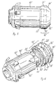
- conductive member 22 In order for varistor disk 24 to function properly, conductive member 22 must be in electrical contact with commutator segments 40 and varistor disk 24 must be in electrical contact with conductive member 22. If proximal end 30 of retaining ring 20 is longer than the combined thickness of varistor disk 24 and conductive member 22, then there will be play between varistor disk 24, conductive member 22, and commutator segments 40. To avoid this problem and ensure the proper electrical contact, a tolerance absorbing member 60 can if necessary be interposed between varistor disk 24 and retaining ring 20. Tolerance absorbing member 60 can take the form of a compressible elastomeric disk, as shown in Figure 1, or a conventional spring or wavy washer, as shown in Figure 4.
- Conductive member 22' is substantially identical to conductive member 22 described above with respect to the first embodiment shown in Figures 1 and 2.
- a tolerance absorbing member 60 as described above can be used if required between retaining ring 20' and varistor disk 24' in order to insure proper contact between the various elements.
Landscapes
- Engineering & Computer Science (AREA)
- Power Engineering (AREA)
- Motor Or Generator Current Collectors (AREA)
- Thermistors And Varistors (AREA)
- Dc Machiner (AREA)
Claims (14)
- Varistorscheiben-Anordnung zur Montage an einem Kommutator (10), welcher an einer Motorwelle (S) angebracht ist, wobei der Kommutator (10) eine Vielzahl peripherer Segmente (40) aufweist und die Varistorscheiben-Anordnungdadurch gekennzeichnet,eine Varistorscheibe (24) undeinen nicht leitfähigen Haltering (20) zum Halten der Varistorscheibe (24) an ihrem Platz aufweist,daß der Haltering (20) eine durchgehende axiale Bohrung aufweist, welche so dimensioniert ist, um einen Reibungsschluß mit der Motorwelle (S) zu gewährleisten, und ein proximales Ende (30) zur Ausrichtung, welches einer Kommutator-Grundfläche (14) zugewandt ist, sowie ein distales Ende (32) zur Ausrichtung, welches von der Kommutator-Grundfläche (14) abgewandt ist,daß ein leitfähiges Glied (22) vorgesehen ist, wobei das leitfähige Glied (22) zur Anordnung an der Kommutator-Grundfläche (14) so konfiguriert ist, daß die Motorwelle (S) durch es hindurch verläuft,daß die Varistorscheibe (24) zur Einfügung zwischen dem leitfähigen Glied (22) und dem proximalen Ende (30) des Halterings (20) so gestaltet ist, daß die Motorwelle (S) durch sie hindurch verläuft, unddaß das leitfähige Glied (22) so gestaltet ist, daß es Strom längs seiner Dicke von der Kommutator-Grundfläche (14) zu der Varistorscheibe (24) leitet, aber keinen Strom zwischen benachbarten Kommutator-Segmenten (40) leitet.
- Varistorscheiben-Anordnung nach Anspruch 1,
dadurch gekennzeichnet,
daß das leitfähige Glied (22) zusammendrückbar ist. - Varistorscheiben-Anordnung nach Anspruch 1 oder 2,
dadurch gekennzeichnet,
daß das proximale Ende (30) des Halterings (20) eingehalst ist und das leitfähige Glied (22) und die Varistorscheibe (24) im wesentlichen kreisförmig sind und innere Durchmesser aufweisen, die so dimensioniert sind, daß sie ungehindert über die Motorwelle (S) geführt werden können und das proximale Ende (30) des Halterings (20) aufnehmen können. - Varistorscheiben-Anordnung nach Anspruch 1 oder 2,
dadurch gekennzeichnet,
daß die Kommutator-Grundfläche (14) eine Verlängerung (14') aufweist, welche mit mindestens einer ebenen Seite (14a') ausgebildet ist, und der innere Durchmesser der Varistorscheibe (24') eine zur ebenen Seite (14a') der Verlängerung (14') entsprechende ebene Seite (50') aufweist, wobei die ebene Seite (14a') der Verlängerung (14') so orientiert ist, daß sich eine geeignete Ausrichtung der Varistorscheibe (24') mit dem Kommutator (10') ergibt. - Varistorscheiben-Anordnung nach Anspruch 1,
dadurch gekennzeichnet,
daß ein Toleranzen aufnehmendes Glied (60) zur Einfügung zwischen der Varistorscheibe (24) und dem Haltering (20) vorgesehen ist. - Varistorscheiben-Anordnung nach Anspruch 5,
dadurch gekennzeichnet,
daß das Toleranzen aufnehmende Glied (60) eine herkömmliche gewellte Unterlegscheibe aufweist. - Varistorscheiben-Anordnung nach Anspruch 5,
dadurch gekennzeichnet,
daß das Toleranzen aufnehmende Glied (60) ein zusammendrückbares Elastomer aufweist. - Varistorscheiben-Anordnung nach Anspruch 1,
dadurch gekennzeichnet,
daß das leitfähige Glied (22) einen extrudierten Gummiring aufweist, an dessen äußerem Umfang eine Vielzahl beabstandeter Nuten (22a) und eine Lage leitfähigen Materials (22b), welches in die Nuten (22a) extrudiert ist, vorgesehen sind. - Varistorscheiben-Anordnung nach Anspruch 3,
dadurch gekennzeichnet,
daß das proximale Ende (30) des Halteringes (20) einen Umfang, der mit einer ebenen Seite (38) ausgebildet ist, aufweist, und daß der innere Durchmesser der Varistorscheibe (24) mit einer ebenen Seite (50) versehen ist, die der ebenen Seite (38) des proximalen Endes (30) des Halteringes (20) entspricht, wobei die ebene Seite (38) des Halteringes (20) so orientiert ist, daß sich eine geeignete Ausrichtung der Varistorscheibe (24) mit dem Kommutator (10) ergibt. - Varistorscheiben-Anordnung nach einem der Ansprüche 1 bis 9,
dadurch gekennzeichnet,
daß die Varistorscheiben-Anordnung (12) ein Teil eines Motorläufers mitist.einer Motorwelle (S) undeinem Kommutator (10), der konzentrisch auf der Motorwelle (S) montiert ist, wobei der Kommutator (10) eine Grundfläche (14) und eine Vielzahl peripherer Segmente (40) aufweist, - Verfahren zur Montage einer Varistorscheibe (24) an eine Grundfläche (14) eines Kommutators (10), welcher auf eine Motorwelle (S) montiert ist, mit den Schritten:Positionieren eines kreisförmigen leitfähigen Gliedes (22) an der Kommutator-Grundfläche (14),Positionieren einer kreisförmigen Varistorscheibe (24) angrenzend an das leitfähige Glied (22) undSichern des leitfähigen Gliedes (22) und der Varistorscheibe (24) an deren Plätzen, unter Zuhilfenahme eines nicht leitfähigen Halterings (20), der eine durchgehende Bohrung aufweist, die so dimensioniert ist, um einen Reibungsschluß mit der Motorwelle (S) zu gewährleisten.
- Verfahren nach Anspruch 11,
mit dem weiteren Schritt des Positionierens eines Toleranzen aufnehmenden Gliedes (60) zwischen der Varistorscheibe (24) und dem Haltering (20). - Verfahren nach Anspruch 11,
wobei der Kommutator (10) eine Vielzahl peripherer Segmente (40) aufweist, der Haltering (20) ein eingehalstes nahes Ende, welches der Kommutator-Grundfläche (14) zugewandt ist, aufweist, das leitfähige Glied (22) und die Varistorscheibe (24) so dimensionierte innere Durchmesser haben, daß sie ungehindert über die Motorwelle (S) geführt werden können und sie das proximale Ende (30) des Halteringes (20) aufnehmen können, die Außenfläche des distalen Endes (32) des Halteringes (20) mit zumindest einer ebenen Seite (36a) ausgebildet ist, die Außenseite des proximalen Endes (30) des Halteringes (20) mit einer ebenen Seite (38) ausgebildet ist und der innere Durchmesser der Varistorscheibe (24) mit einer ebenen Seite (50) versehen ist, die komplementär zu der ebenen Seite (38) des proximalen Endes (30) des Halteringes (20) ist, wobei das Verfahren weiterhin die Schritte:aufweist.Ausrichten der ebenen Seite (50) der Varistorscheibe (24) mit der ebenen Seite (38) des proximalen Endes (30) des Halteringes (20) undAusrichten der ebenen Seite (36a) des distalen Endes (32) des Halteringes (20) mit einem der Segmente (40) des Kommutators (10) - Verfahren nach Anspruch 11,
wobei der Kommutator (10) eine Vielzahl peripherer Segmente (40) aufweist, die Kommutator-Grundfläche (14) eine Verlängerung (14') aufweist, welche mit zumindest einer ebenen Seite (14a') ausgebildet ist, und der innere Durchmesser der Varistorscheibe (24) mit einer ebenen Seite (50') versehen ist, die komplementär zu der ebenen Seite (14a') der Verlängerung (14') ist, wobei das Verfahren weiterhin den Schritt:aufweist.Ausrichten der ebenen Seite (50') der Varistorscheibe (24) mit der ebenen Seite (14a') der Verlängerung (14') der Kommutator-Grundfläche (14)
Priority Applications (3)
| Application Number | Priority Date | Filing Date | Title |
|---|---|---|---|
| DE69502016T DE69502016T2 (de) | 1995-08-01 | 1995-08-01 | Zusammenbau eines scheibenförmigen Varistors und Montageverfahren eines scheibenförmigen Varistors |
| EP95112093A EP0757424B1 (de) | 1995-08-01 | 1995-08-01 | Zusammenbau eines scheibenförmigen Varistors und Montageverfahren eines scheibenförmigen Varistors |
| AT95112093T ATE164972T1 (de) | 1995-08-01 | 1995-08-01 | Zusammenbau eines scheibenförmigen varistors und montageverfahren eines scheibenförmigen varistors |
Applications Claiming Priority (1)
| Application Number | Priority Date | Filing Date | Title |
|---|---|---|---|
| EP95112093A EP0757424B1 (de) | 1995-08-01 | 1995-08-01 | Zusammenbau eines scheibenförmigen Varistors und Montageverfahren eines scheibenförmigen Varistors |
Publications (2)
| Publication Number | Publication Date |
|---|---|
| EP0757424A1 EP0757424A1 (de) | 1997-02-05 |
| EP0757424B1 true EP0757424B1 (de) | 1998-04-08 |
Family
ID=8219495
Family Applications (1)
| Application Number | Title | Priority Date | Filing Date |
|---|---|---|---|
| EP95112093A Expired - Lifetime EP0757424B1 (de) | 1995-08-01 | 1995-08-01 | Zusammenbau eines scheibenförmigen Varistors und Montageverfahren eines scheibenförmigen Varistors |
Country Status (3)
| Country | Link |
|---|---|
| EP (1) | EP0757424B1 (de) |
| AT (1) | ATE164972T1 (de) |
| DE (1) | DE69502016T2 (de) |
Cited By (1)
| Publication number | Priority date | Publication date | Assignee | Title |
|---|---|---|---|---|
| DE102011119311A1 (de) * | 2011-11-23 | 2013-05-23 | Brose Fahrzeugteile GmbH & Co. Kommanditgesellschaft, Würzburg | Kommutatoreinrichtung für eine rotierende elektrische Maschine |
Family Cites Families (6)
| Publication number | Priority date | Publication date | Assignee | Title |
|---|---|---|---|---|
| JPS6029193B2 (ja) | 1975-08-30 | 1985-07-09 | 松下電工株式会社 | 整流子 |
| JPS5417008U (de) * | 1977-07-08 | 1979-02-03 | ||
| SU746790A1 (ru) | 1978-03-16 | 1980-07-07 | Предприятие П/Я В-2880, Томский Политехнический Институт Им.С.М.Кирова | Устройство подавлени радиопомех и снижени искрени коллекторных электрических машин |
| JPS622358U (de) | 1985-06-18 | 1987-01-08 | ||
| GB2202686B (en) | 1987-03-23 | 1991-08-14 | Johnson Electric Ind Mfg | An armature for an electric motor |
| ES2078668T3 (es) * | 1991-11-12 | 1995-12-16 | Johnson Electric Sa | Colector ensamblado. |
-
1995
- 1995-08-01 AT AT95112093T patent/ATE164972T1/de not_active IP Right Cessation
- 1995-08-01 DE DE69502016T patent/DE69502016T2/de not_active Expired - Lifetime
- 1995-08-01 EP EP95112093A patent/EP0757424B1/de not_active Expired - Lifetime
Cited By (2)
| Publication number | Priority date | Publication date | Assignee | Title |
|---|---|---|---|---|
| DE102011119311A1 (de) * | 2011-11-23 | 2013-05-23 | Brose Fahrzeugteile GmbH & Co. Kommanditgesellschaft, Würzburg | Kommutatoreinrichtung für eine rotierende elektrische Maschine |
| DE102011119311B4 (de) * | 2011-11-23 | 2014-05-28 | Brose Fahrzeugteile GmbH & Co. Kommanditgesellschaft, Würzburg | Kommutatoreinrichtung für eine rotierende elektrische Maschine |
Also Published As
| Publication number | Publication date |
|---|---|
| ATE164972T1 (de) | 1998-04-15 |
| DE69502016T2 (de) | 1998-08-27 |
| EP0757424A1 (de) | 1997-02-05 |
| DE69502016D1 (de) | 1998-05-14 |
Similar Documents
| Publication | Publication Date | Title |
|---|---|---|
| US5895990A (en) | Miniature motor | |
| EP0714159B1 (de) | Läufer für einen Elektromotor | |
| US6285106B1 (en) | Commutator | |
| US4859893A (en) | Commutator with resiliently clamped resistor ring | |
| PL343026A1 (en) | Surge diverter | |
| US5473212A (en) | Varistor disk assembly | |
| US11101712B2 (en) | Motor, end cap and manufacturing method thereof | |
| CA2173357C (en) | Electrical assembly | |
| KR900003403Y1 (ko) | 소형 모터 | |
| KR100318843B1 (ko) | 소음억제정류자와소음억제요소를정류자단편에접속하는방법 | |
| KR100397238B1 (ko) | 평면 정류자 및 그 제조방법 | |
| KR900000829Y1 (ko) | 소형 모터의 전압 흡수장치 | |
| EP0542451A1 (de) | Zusammengebauter Kommutator | |
| EP0757424B1 (de) | Zusammenbau eines scheibenförmigen Varistors und Montageverfahren eines scheibenförmigen Varistors | |
| EP0437960A1 (de) | Rotierende Gleichrichteranordnung | |
| JP4625016B2 (ja) | 電気機器用の整流子 | |
| JP4733032B2 (ja) | 電気機械のための整流子 | |
| US5050033A (en) | Back-up surge arresters | |
| GB2096837A (en) | Brushgear for electric motors | |
| JP2022117541A (ja) | リング状バリスタ付き整流子を備える直流モータ及びその製法 | |
| JPS6035947A (ja) | 小型モ−タ用の雑音防止器付き整流子 | |
| GB1574229A (en) | Spark quencher attachment for an electric motor | |
| JPH0670471U (ja) | ノイズ防止コンミテータ | |
| JPH07222407A (ja) | 整流子 | |
| CN117321708A (zh) | 具有扼流线圈的电气装置 |
Legal Events
| Date | Code | Title | Description |
|---|---|---|---|
| PUAI | Public reference made under article 153(3) epc to a published international application that has entered the european phase |
Free format text: ORIGINAL CODE: 0009012 |
|
| 17P | Request for examination filed |
Effective date: 19960510 |
|
| AK | Designated contracting states |
Kind code of ref document: A1 Designated state(s): AT BE CH DE DK ES FR GB GR IE IT LI LU MC NL PT SE |
|
| 17Q | First examination report despatched |
Effective date: 19970312 |
|
| GRAG | Despatch of communication of intention to grant |
Free format text: ORIGINAL CODE: EPIDOS AGRA |
|
| GRAG | Despatch of communication of intention to grant |
Free format text: ORIGINAL CODE: EPIDOS AGRA |
|
| GRAH | Despatch of communication of intention to grant a patent |
Free format text: ORIGINAL CODE: EPIDOS IGRA |
|
| GRAH | Despatch of communication of intention to grant a patent |
Free format text: ORIGINAL CODE: EPIDOS IGRA |
|
| GRAA | (expected) grant |
Free format text: ORIGINAL CODE: 0009210 |
|
| AK | Designated contracting states |
Kind code of ref document: B1 Designated state(s): AT BE CH DE DK ES FR GB GR IE IT LI LU MC NL PT SE |
|
| PG25 | Lapsed in a contracting state [announced via postgrant information from national office to epo] |
Ref country code: NL Free format text: LAPSE BECAUSE OF FAILURE TO SUBMIT A TRANSLATION OF THE DESCRIPTION OR TO PAY THE FEE WITHIN THE PRESCRIBED TIME-LIMIT Effective date: 19980408 Ref country code: LI Free format text: LAPSE BECAUSE OF FAILURE TO SUBMIT A TRANSLATION OF THE DESCRIPTION OR TO PAY THE FEE WITHIN THE PRESCRIBED TIME-LIMIT Effective date: 19980408 Ref country code: IT Free format text: LAPSE BECAUSE OF FAILURE TO SUBMIT A TRANSLATION OF THE DESCRIPTION OR TO PAY THE FEE WITHIN THE PRESCRIBED TIME-LIMIT;WARNING: LAPSES OF ITALIAN PATENTS WITH EFFECTIVE DATE BEFORE 2007 MAY HAVE OCCURRED AT ANY TIME BEFORE 2007. THE CORRECT EFFECTIVE DATE MAY BE DIFFERENT FROM THE ONE RECORDED. Effective date: 19980408 Ref country code: GR Free format text: LAPSE BECAUSE OF FAILURE TO SUBMIT A TRANSLATION OF THE DESCRIPTION OR TO PAY THE FEE WITHIN THE PRESCRIBED TIME-LIMIT Effective date: 19980408 Ref country code: ES Free format text: THE PATENT HAS BEEN ANNULLED BY A DECISION OF A NATIONAL AUTHORITY Effective date: 19980408 Ref country code: CH Free format text: LAPSE BECAUSE OF FAILURE TO SUBMIT A TRANSLATION OF THE DESCRIPTION OR TO PAY THE FEE WITHIN THE PRESCRIBED TIME-LIMIT Effective date: 19980408 Ref country code: BE Free format text: LAPSE BECAUSE OF FAILURE TO SUBMIT A TRANSLATION OF THE DESCRIPTION OR TO PAY THE FEE WITHIN THE PRESCRIBED TIME-LIMIT Effective date: 19980408 Ref country code: AT Free format text: LAPSE BECAUSE OF FAILURE TO SUBMIT A TRANSLATION OF THE DESCRIPTION OR TO PAY THE FEE WITHIN THE PRESCRIBED TIME-LIMIT Effective date: 19980408 |
|
| REF | Corresponds to: |
Ref document number: 164972 Country of ref document: AT Date of ref document: 19980415 Kind code of ref document: T |
|
| REG | Reference to a national code |
Ref country code: CH Ref legal event code: EP |
|
| REF | Corresponds to: |
Ref document number: 69502016 Country of ref document: DE Date of ref document: 19980514 |
|
| PG25 | Lapsed in a contracting state [announced via postgrant information from national office to epo] |
Ref country code: SE Free format text: LAPSE BECAUSE OF FAILURE TO SUBMIT A TRANSLATION OF THE DESCRIPTION OR TO PAY THE FEE WITHIN THE PRESCRIBED TIME-LIMIT Effective date: 19980708 Ref country code: PT Free format text: LAPSE BECAUSE OF FAILURE TO SUBMIT A TRANSLATION OF THE DESCRIPTION OR TO PAY THE FEE WITHIN THE PRESCRIBED TIME-LIMIT Effective date: 19980708 Ref country code: DK Free format text: LAPSE BECAUSE OF FAILURE TO SUBMIT A TRANSLATION OF THE DESCRIPTION OR TO PAY THE FEE WITHIN THE PRESCRIBED TIME-LIMIT Effective date: 19980708 |
|
| REG | Reference to a national code |
Ref country code: IE Ref legal event code: FG4D Free format text: 79775 |
|
| PG25 | Lapsed in a contracting state [announced via postgrant information from national office to epo] |
Ref country code: LU Free format text: LAPSE BECAUSE OF NON-PAYMENT OF DUE FEES Effective date: 19980801 Ref country code: IE Free format text: LAPSE BECAUSE OF NON-PAYMENT OF DUE FEES Effective date: 19980801 |
|
| ET | Fr: translation filed | ||
| NLV1 | Nl: lapsed or annulled due to failure to fulfill the requirements of art. 29p and 29m of the patents act | ||
| REG | Reference to a national code |
Ref country code: CH Ref legal event code: PL |
|
| PLBE | No opposition filed within time limit |
Free format text: ORIGINAL CODE: 0009261 |
|
| STAA | Information on the status of an ep patent application or granted ep patent |
Free format text: STATUS: NO OPPOSITION FILED WITHIN TIME LIMIT |
|
| PG25 | Lapsed in a contracting state [announced via postgrant information from national office to epo] |
Ref country code: MC Free format text: LAPSE BECAUSE OF NON-PAYMENT OF DUE FEES Effective date: 19990228 |
|
| 26N | No opposition filed | ||
| REG | Reference to a national code |
Ref country code: GB Ref legal event code: IF02 |
|
| PGFP | Annual fee paid to national office [announced via postgrant information from national office to epo] |
Ref country code: FR Payment date: 20130702 Year of fee payment: 19 |
|
| PGFP | Annual fee paid to national office [announced via postgrant information from national office to epo] |
Ref country code: GB Payment date: 20130731 Year of fee payment: 19 |
|
| PGFP | Annual fee paid to national office [announced via postgrant information from national office to epo] |
Ref country code: DE Payment date: 20140814 Year of fee payment: 20 |
|
| GBPC | Gb: european patent ceased through non-payment of renewal fee |
Effective date: 20140801 |
|
| REG | Reference to a national code |
Ref country code: FR Ref legal event code: ST Effective date: 20150430 |
|
| PG25 | Lapsed in a contracting state [announced via postgrant information from national office to epo] |
Ref country code: GB Free format text: LAPSE BECAUSE OF NON-PAYMENT OF DUE FEES Effective date: 20140801 |
|
| REG | Reference to a national code |
Ref country code: DE Ref legal event code: R071 Ref document number: 69502016 Country of ref document: DE |
|
| PG25 | Lapsed in a contracting state [announced via postgrant information from national office to epo] |
Ref country code: FR Free format text: LAPSE BECAUSE OF NON-PAYMENT OF DUE FEES Effective date: 20140901 |