EP0757965A2 - Dispositif pour guider une feuille fraîchement imprimée - Google Patents
Dispositif pour guider une feuille fraîchement imprimée Download PDFInfo
- Publication number
- EP0757965A2 EP0757965A2 EP96112087A EP96112087A EP0757965A2 EP 0757965 A2 EP0757965 A2 EP 0757965A2 EP 96112087 A EP96112087 A EP 96112087A EP 96112087 A EP96112087 A EP 96112087A EP 0757965 A2 EP0757965 A2 EP 0757965A2
- Authority
- EP
- European Patent Office
- Prior art keywords
- sheet
- nozzle configuration
- air nozzles
- guide surface
- guide
- Prior art date
- Legal status (The legal status is an assumption and is not a legal conclusion. Google has not performed a legal analysis and makes no representation as to the accuracy of the status listed.)
- Granted
Links
- 238000007664 blowing Methods 0.000 claims description 39
- 210000002105 tongue Anatomy 0.000 claims description 11
- 230000008021 deposition Effects 0.000 claims description 5
- 239000004606 Fillers/Extenders Substances 0.000 abstract 1
- 238000005520 cutting process Methods 0.000 description 4
- 230000002349 favourable effect Effects 0.000 description 2
- 210000001503 joint Anatomy 0.000 description 2
- 238000004519 manufacturing process Methods 0.000 description 2
- 230000003213 activating effect Effects 0.000 description 1
- 230000000694 effects Effects 0.000 description 1
- 238000000034 method Methods 0.000 description 1
- 238000010408 sweeping Methods 0.000 description 1
- 230000007704 transition Effects 0.000 description 1
- 238000009827 uniform distribution Methods 0.000 description 1
- 238000011144 upstream manufacturing Methods 0.000 description 1
Images


Classifications
-
- B—PERFORMING OPERATIONS; TRANSPORTING
- B65—CONVEYING; PACKING; STORING; HANDLING THIN OR FILAMENTARY MATERIAL
- B65H—HANDLING THIN OR FILAMENTARY MATERIAL, e.g. SHEETS, WEBS, CABLES
- B65H5/00—Feeding articles separated from piles; Feeding articles to machines
- B65H5/22—Feeding articles separated from piles; Feeding articles to machines by air-blast or suction device
- B65H5/228—Feeding articles separated from piles; Feeding articles to machines by air-blast or suction device by air-blast devices
-
- B—PERFORMING OPERATIONS; TRANSPORTING
- B65—CONVEYING; PACKING; STORING; HANDLING THIN OR FILAMENTARY MATERIAL
- B65H—HANDLING THIN OR FILAMENTARY MATERIAL, e.g. SHEETS, WEBS, CABLES
- B65H2801/00—Application field
- B65H2801/24—Post -processing devices
- B65H2801/31—Devices located downstream of industrial printers
Definitions
- the invention relates to a guide device for a freshly printed sheet, the front edge of which sweeps an imaginary guide surface along a sheet running direction perpendicular to the front edge, with a sheet guide surface following the guide surface and spaced apart therefrom in the form of a surface of a guide plate arrangement and with the sheet guide surface being distributed and opening into it Blown air openings, and a sheet-fed printing machine with such a guide device.
- a guide device of the type mentioned is known for example from the document DE 43 08 276 A1.
- blow nozzles are fitted into openings in a baffle, which in operation emit a jet of blown air from a respective flow channel arranged at an angle to the bend guide surface and opening into the bend guide surface.
- the flow channels are aligned in the sheet running direction and the blowing nozzles are distributed over the sheet guide surface. The blowing air exiting the flow channels during operation creates an air flow between the bend and the bend guide surface, by means of which contact of the bend with the bow guide surface is to be prevented.
- a guide device for sheets which is composed of a plurality of nozzle tubes which extend below the guide surface covered by the front edge of a sheet in the direction of sheet travel. Blown air openings of blown air nozzles inserted into the nozzle tubes, by means of which the swirl flows sweeping the bends can be generated, open at the top of these nozzle tubes.
- the invention has for its object to perform positively guided sheets on its leading edge without touching a sheet guide surface over them.
- Equipping the baffle plate arrangement according to the invention with blown air nozzles of the first and at least one second nozzle configuration specified in claim 1 enables a largely closed air cushion to be provided between the sheet guide surface and the sheet.
- this configuration enables the load capacity of the air cushion mentioned to be optimized over the entire area of the sheet guiding surface covered by the sheet.
- a particularly advantageous embodiment of a guide device according to the invention results from the fact that in sections which are particularly at risk with regard to possible color deposition on the sheet guide surface along the sheet guide surface of the second nozzle configuration, associated blow air nozzles form at least a substantial part of the blow air nozzles provided in these sections.
- a configuration which is favorable in terms of production results from the fact that the blown air openings of the blown air nozzles belonging to the second nozzle configuration are represented by gaps formed in the curved guide surface, which are caused by angled in the same direction, away from the guide surface, of regions of a guide plate section of the guide plate arrangement which are at least essentially extend between imaginary pairs of concentric circles over at least substantially the same and evenly distributed angles over 360 ° and form guide plate tongues; which are each connected in one piece to the guide plate section at corresponding ends of the angled regions.
- a production-technically and functionally advantageous embodiment of the blown air nozzles of the second nozzle configuration is characterized in that the blown air openings thereof are represented by gaps formed in the sheet guide surface, which are created by channel sections pressed into the guide plate arrangement, which extend at least substantially between imaginary pairs of concentric circles over at least substantially the same and uniformly distributed over 360 ° angles, the channel sections having respective channel bottoms which extend from the arc guide surface at corresponding first ends of the channel sections, and with respect to this from one of the guide surface are pointing inclined, and which have open channel end faces at second ends opposite the first ends.
- blowing air nozzles of the second nozzle configuration is distinguished by the fact that their blowing air openings are represented by gaps formed in the arc guiding surface, which are at least essentially distributed between imaginary pairs of concentric circles over at least substantially the same and uniformly over 360 ° Extend the angle, a respective one of the gaps being created by a first cut in the guide plate arrangement, which is radially oriented at least essentially in the circumferential direction of the concentric circles, with respect to the respective pair, with a respective one of the gaps of the concentric circles at least substantially radially extending second section and a deformation of each located between the respective pair of concentric circles and along the first En section of extending areas of the baffle arrangement in such a way that cut edges of these areas formed by the first and second cut, forming a gap running along these cut edges between these cut edges and corresponding cut edges of the undeformed part of the baffle arrangement in a direction pointing away from the guide surface in the same direction with respect to the sheet guide surface are
- a respective one of the deformed areas is formed in the manner of a notch with a maximally lowered notch line, which starting from a deepest level at a corner of a respective one of the deformed areas corresponding to the first end of the first cut, increases with increasing distance from the first cut.
- nozzle bodies are attached to a side of the guide plate section facing away from the guide surface, of which a respective one is assigned to the gaps distributed over 360 ° in each case, and are coiled in a respective one of the nozzle bodies with blown air Channels are formed, each of which communicates with a respective one of the gaps distributed over 360 °.
- a preferred embodiment of the guide device is characterized in that blown air shafts are provided which run transversely to the sheet running direction and through which blown air nozzles can be applied.
- This embodiment offers the possibility of activating the blown air nozzles line by line in lines running transversely to the sheet running direction, independently of adjacent lines, with blown air, so that line by line different parameters of the blown air can be provided.
- an inlet area of the sheet guide surface is equipped with blowing air nozzles of a third nozzle configuration, the blowing air nozzles of the third nozzle configuration having blowing air openings in the form of bores in the guide plate arrangement.
- an inlet area of the sheet guiding surface is equipped with blown air openings of the first nozzle configuration, which are arranged in such a way that the air jet bundles that can be generated are directed in the opposite direction to the sheet running direction.
- the air jet bundles that can be generated by means of the blown air nozzles of the first nozzle configuration are oriented opposite to the direction of sheet travel, and the blowing air nozzles of the first nozzle configuration follow the blowing air nozzles of the third nozzle configuration in the sheet running direction.
- blowing air nozzles belonging to the first nozzle configuration is preferably provided in regions of the sheet guiding surface which are upstream of the sheet guiding surface with respect to an inlet area of the sheet guiding surface, such that the air jet bundles which can be generated by means of these blowing air nozzles are oriented at least essentially in the sheet running direction.
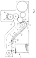
- the leading edges of the respective sheets 1 are clamped during their transport in the direction of a stacking device 2 in a delivery of a sheet printing machine by means of gripper systems 3 which are articulated on revolving chains 4, so that the leading edges of the sheets 1 are intended Coat guide surface 5 in a direction of sheet travel perpendicular to the leading edges (arrow P).
- the guide surface 5 is followed by a sheet guide surface 6 spaced from it in the form of a surface of a guide plate arrangement 7.
- the guide plate arrangement 7 comprises guide plate sections 7.1, 7.2, 7.3, which are joined to one another at joints 8.1, 8.2 running transversely to the sheet running direction.
- the guide plate arrangement 7 forms an inlet area 6.1 of the sheet guide surface 6.
- This inlet area 6.1 is located in the immediate vicinity of the printing cylinder 23 of a printing unit 24 of a printing machine which transfers the sheets 1 to a gripper system 3.
- the printing unit 24 is represented in particular by the representation of the already mentioned printing cylinder 23, an offset cylinder 25 and a plate cylinder 26.
- An optional dampening system has not been shown and an inking unit which works together with the plate cylinder 26 is only shown in simplified form by application rollers 27 of the same.
- the representation of grippers of the printing cylinder 23 has been dispensed with, which opposes the sheets 1 to a respective gripper system 3.
- the latter is provided in the inlet area 6.1 with recesses 28 which can be seen in FIG. 2.
- blowing air nozzles 9 belonging to the first nozzle configuration are designed such that so that aligned air jets can be generated with respect to the sheet running direction.
- the constructive design of a respective one of the blowing air nozzles 9 provides for this in each case an inclined lowering, directed away from the guide surface 5, of an approximately annular segment-shaped region in a guide plate section 7.1 or 7.2 or 7.3 of such a type that there is a radially inner part with respect to the annular segment-shaped region lowered cutting edge, which forms an air gap 12 between itself and the corresponding cutting edge on the undeformed baffle section 7.1 or 7.2 or 7.3, through which operationally blown air flows, which subsequently flows through a blown air opening 9.1 in the form of a from the lowered area in the Arc guide surface 6 left gap flows out of the sheet guide surface 6.
- the blowing air nozzles 9 designed in this way are - as seen in the direction of sheet travel - oriented in areas of the sheet guiding surface 6 located downstream of an inlet area 6.1 which will be explained later, such that the inclined, approximately annular section area of the guide plate sections 7.1 or 7.2 or 7.3, starting from the mentioned gap 12, increases at least substantially in the direction of sheet travel.
- the air jet bundles that can be generated with the blown air nozzles 9 are thus aligned with respect to the sheet running direction and have a main flow direction pointing in the sheet running direction.
- blowing air nozzles 9 are arranged within the above-mentioned areas in such a way that the central jets of the air jet bundles 9 generated on the one hand on the left and on the right with respect to the longitudinal center of the guide plate sections 7.1 or 7.2 or 7.3 are inclined towards one another are that they enclose an opening angle in the direction of sheet travel.
- blown air openings 10.1 are also formed in the form of specially designed gaps in the sheet guide surface 6.
- the gaps mentioned extend over substantially the same and evenly distributed over 360 ° angles between imaginary pairs of concentric circles 13 and 14 and in the example shown have the shape of circular ring sections.
- These gaps are formed by angling away from the guide surface 5 of a respective area of the guide plate section 7.1 or 7.2 or 7.3 having the shape of one of the circular ring sections in such a way that a respective one of these areas forms a guide plate tongue 15 after the angling one end of one of the respective circular ring sections with the guide plate section 7.1 or 7.2 or 7.3 remains integrally connected.
- gaps can also be delimited in a straight line, for example. This also applies to the configurations of the blowing air nozzles 10 ′ and 10 ′′ of the second nozzle configuration described below.
- the gaps in the curved guide surface 6 which represent the blown air openings 10'.1 are formed by channel sections pressed into the guide plate arrangement 7 (see FIG. 3). These extend at least essentially also between imaginary pairs of concentric circles 13, 14 and over at least substantially the same and uniformly distributed angles over 360 °.
- the channel sections have channel floors which are inclined in such a way that they extend from the sheet guide surface 6 at corresponding first ends of the channel sections and are inclined with respect to the latter in a direction pointing away from the guide surface 5. At opposite ends of the channel sections with respect to the first ends, they have open channel end faces.
- the blown air openings 10 ′′. 1 are in turn represented by gaps formed in the sheet guide surface 6, the shape and arrangement of which in principle correspond to the conditions in the described exemplary embodiments according to FIGS. 2 and Fig. 3 correspond.
- a respective one of the gaps was created by a first cut 10 ′′. 2 lying radially on the inside with respect to the respective pair of concentric circles 13 and 14, which is oriented at least substantially in the circumferential direction of the circles 13 and 14, and further by one a first end of the first cut 10 ′′. 2 subsequent second cut 10 ′′. 3, which is oriented at least substantially radially with respect to the circles 13 and 14, and by such a deformation of each of the two concentric circles located between and along of the first section 10 ′′.
- a respective one of the deformed areas is designed in the manner of a notch with a maximally lowered notch line 10 ′′. 5. Starting from the lowest level, this rises at a corner of a respective one of the deformed regions corresponding to the first end of the first cut 10 ′′. 2 with increasing distance from the first cut 10 ′′. 2.
- the notches mentioned as well as the channel bases and guide plate tongues 15 mentioned further above can be formed with a reasonable manufacturing effort with a smooth transition into the sheet guide surface 6. This has an advantageous effect on the flow pattern of the swirl flows generated thereby and, in this respect, has a favorable effect on a contact-free guidance of the bend 1.
- a blower air nozzle 10, 10 ', 10' 'of the second nozzle configuration can be preceded by a nozzle body 16 which can be attached to a side of the guide plate section 7.1, 7.2, 7.3 facing away from the guide surface 5 (see FIG. 4).
- This has helical channels 17 which can be acted upon by blown air, of which a respective one communicates with a respective one of the gaps of the sheet guiding surface 6 distributed over 360 °.
- the channels 17 are wound in such a way that in a first embodiment they turn clockwise and in a second embodiment counterclockwise into a respective gap.
- the guide plate tongues 15 assigned to a respective nozzle body 16 and distributed over 360 ° are angled in the same direction with respect to the guide plate section 7.1 or 7.2 or 7.3, respectively, in such a way that they rotate clockwise in a first embodiment and in a second Embodiment rise counterclockwise from the free end of a respective guide plate tongue 15 in the direction of the sheet guide surface 6.
- the slope corresponds to that of the coiled channels 17 in the nozzle body 16.
- the nozzle body 16 is formed from a circular cylindrical bowl 18 and a worm 19 fitted therein with a number of gears 15 adapted to the number of guide plate tongues 15 distributed over 360 °.
- the coils of the screw 19 thus covered by the bowl 18 form the channels 17, which in the present example have a rectangular cross section.
- a respective one of the guide plate tongues 15 distributed over 360 ° protrudes into a respective channel 17 of the nozzle body 16 and, with an underside of the respective guide plate tongue 15 facing away from the sheet guide surface 6, lies against a flank of a respective one of the helixes forming the screw 19 facing the sheet guide surface 6.
- the blowing air nozzles 9 and 10 of the first and the second nozzle configuration are distributed along lines Z1 to Z3 etc. running across the sheet direction (arrow P in FIG. 1) etc. over the sheet guide surface 6.
- a respective blower air duct 21 is assigned to a respective line Z1 to Z3 etc., by means of which blast air nozzles arranged along this line can be acted upon by blown air.
- the nozzle bodies 16 assigned to the blowing air nozzles 10 arranged along one of the lines Z2 to Z3 etc. of the second nozzle configuration are enclosed in the blowing air shaft 21 assigned to the corresponding lines Z2 to Z3 etc. according to FIG.
- the respective blower duct 21 is attached with an open side thereof to a side of the guide plate section 7.1 or 7.2 or 7.3 facing away from the sheet guide surface 6 and is covered by this.
- the guide plate arrangement 7 naturally has an inlet area 6.1 of the sheet guide surface 6.
- This inlet area 6.1 lies in front of the second line Z2 in the section shown in FIG. 2 from the part of the guide device indicated in FIG. 1 by the circle II in the sheet travel direction (arrow P) .
- said inlet area 6.1 is in particular provided with blown air nozzles 9 of the first nozzle configuration and with blown air nozzles 11 of a third nozzle configuration, which have blown air openings 11.1 in the form of bores in the guide plate section 7.1.
- the blown air openings 11.1 are supplied with blown air from chambers 22.
- a respective one of the chambers 22 is covered on an upper side thereof by means of the guide plate section 7.1. It adjoins the longitudinal direction of the air duct 21 assigned to the first line Z1 in the opposite direction to the sheet running and is connected to the latter via an opening in the longitudinal side of said air duct 21.
- the blown air nozzles 9 arranged along the line Z1 follow the first nozzle configuration in the direction of the sheet travel onto the blown air nozzles 11 of the third nozzle configuration and they are arranged such that that the air jets that can be generated with it are directed in the opposite direction of the sheet travel.
- the corresponding arrangement is achieved in that the inclined, approximately annular section-shaped areas of the guide plate section 7.1 forming the blower air nozzles 9 in the inlet area 6.1 rise counter to the direction of sheet travel.
- a section of the sheet guiding surface 6 following the inlet area 6.1 is to be regarded as a section of the sheet guiding surface 6 which is particularly at risk with regard to possible color deposition, particularly when the sheet guiding surface 6 is curved.
- blowing air nozzles 10 belonging to the second nozzle configuration form at least a substantial part of the blowing air nozzles 9 and 10 provided in this section. Accordingly, in the example shown (FIG. 2), line Z2 immediately following inlet area 6.1 is consistent with that of the second Nozzle configuration associated blow air nozzles 10 occupied. This can also be expedient for one or more lines following in the direction of sheet travel.
- blowing air nozzles 9 of the first nozzle configuration which are oriented such that the central jets of the air jet bundles which can be generated therewith have a main flow direction pointing in the direction of arc travel.
- blowing air nozzles 9 of the first nozzle configuration and blowing air nozzles 10 of the second nozzle configuration can also be provided alternately, as shown by way of example in line Z3.
- the sequence of the blowing air nozzles of the first and the second nozzle configuration within the respective line advantageously changes from line to line.
- a section in which the guide plate sections 7.2 and 7.3 are joined together to form the butt joint 8.2 is to be regarded as a section of the sheet guiding surface 6 which is particularly endangered with regard to possible color deposition.
- a particularly endangered section of the sheet guiding surface 6 with regard to possible color deposition can also be seen in a section in which the sheet guiding surface 6 merges into a further flat section following a flat section with a change of direction.
Landscapes
- Engineering & Computer Science (AREA)
- Mechanical Engineering (AREA)
- Feeding Of Articles By Means Other Than Belts Or Rollers (AREA)
- Delivering By Means Of Belts And Rollers (AREA)
- Supply, Installation And Extraction Of Printed Sheets Or Plates (AREA)
- Discharge By Other Means (AREA)
- Advancing Webs (AREA)
- Registering, Tensioning, Guiding Webs, And Rollers Therefor (AREA)
- Wrappers (AREA)
- Liquid Developers In Electrophotography (AREA)
- Separation, Sorting, Adjustment, Or Bending Of Sheets To Be Conveyed (AREA)
Applications Claiming Priority (4)
| Application Number | Priority Date | Filing Date | Title |
|---|---|---|---|
| DE19529119 | 1995-08-08 | ||
| DE1995129119 DE19529119A1 (de) | 1995-08-08 | 1995-08-08 | Leiteinrichtung für einen frisch beruckten Bogen |
| DE19628620 | 1996-07-16 | ||
| DE19628620A DE19628620A1 (de) | 1995-08-08 | 1996-07-16 | Leiteinrichtung für einen frisch bedruckten Bogen |
Publications (3)
| Publication Number | Publication Date |
|---|---|
| EP0757965A2 true EP0757965A2 (fr) | 1997-02-12 |
| EP0757965A3 EP0757965A3 (fr) | 1997-02-26 |
| EP0757965B1 EP0757965B1 (fr) | 1999-05-26 |
Family
ID=26017529
Family Applications (1)
| Application Number | Title | Priority Date | Filing Date |
|---|---|---|---|
| EP96112087A Expired - Lifetime EP0757965B1 (fr) | 1995-08-08 | 1996-07-26 | Dispositif pour guider une feuille fraíchement imprimée |
Country Status (6)
| Country | Link |
|---|---|
| US (1) | US5988633A (fr) |
| EP (1) | EP0757965B1 (fr) |
| JP (1) | JP3850443B2 (fr) |
| AT (1) | ATE180461T1 (fr) |
| DE (2) | DE19628620A1 (fr) |
| WO (1) | WO1997006087A1 (fr) |
Cited By (2)
| Publication number | Priority date | Publication date | Assignee | Title |
|---|---|---|---|---|
| CN101531292B (zh) * | 2008-03-10 | 2012-08-08 | 海德堡印刷机械股份公司 | 印刷机及其收纸装置 |
| EP2962971A4 (fr) * | 2013-02-28 | 2016-04-27 | Fujifilm Corp | Dispositif de transport de papier et dispositif de formation d'image |
Families Citing this family (17)
| Publication number | Priority date | Publication date | Assignee | Title |
|---|---|---|---|---|
| JPH10129886A (ja) * | 1996-10-15 | 1998-05-19 | Heidelberger Druckmas Ag | 枚葉紙処理機械の自動給紙機における枚葉紙用紙差し板 |
| DE19810387C1 (de) * | 1998-03-11 | 1999-07-29 | Autz & Herrmann Maschf | Bogenleiteinrichtung |
| US6585263B1 (en) * | 2000-02-02 | 2003-07-01 | Heidelberger Druckmaschinen Ag | Deceleration drum assembly containing air guides |
| DE10131607A1 (de) * | 2000-07-28 | 2002-02-07 | Heidelberger Druckmasch Ag | Ausleger einer flächige Bedruckstoffe verarbeitenden Maschine |
| DE10042888A1 (de) * | 2000-08-31 | 2002-03-14 | Heidelberger Druckmasch Ag | Bogenleiteinrichtung |
| US6598874B2 (en) * | 2000-12-05 | 2003-07-29 | Heidelberger Druckmaschinen Ag | Method and device for contact-free retention of sheets |
| DE10064588B4 (de) * | 2000-12-22 | 2006-04-13 | Man Roland Druckmaschinen Ag | Vorrichtung zum schwebenden Führen von Bahn- oder Bogenmaterial in einer Verarbeitungsmaschine |
| DE10239708B4 (de) * | 2002-08-29 | 2013-10-17 | Koenig & Bauer Aktiengesellschaft | Vorrichtung zum Leiten und Abbremsen von Bogen im Ausleger einer bogenverarbeitenden Maschine, insbesondere Druckmaschine |
| DE10239709B4 (de) * | 2002-08-29 | 2004-08-26 | Koenig & Bauer Ag | Einrichtung zur Ablage von Bogen im Ausleger einer bogenverarbeitenden Maschine |
| DE10239707B4 (de) * | 2002-08-29 | 2007-09-20 | Koenig & Bauer Aktiengesellschaft | Einrichtung zur Ablage von Bogen im Ausleger einer bogenverarbeitenden Maschine |
| JP4954439B2 (ja) * | 2002-10-21 | 2012-06-13 | ハイデルベルガー ドルツクマシーネン アクチエンゲゼルシヤフト | 空気圧式の枚葉紙案内装置を備える枚葉紙処理機械 |
| DE10343428B4 (de) | 2002-10-25 | 2021-02-25 | Heidelberger Druckmaschinen Ag | Bogen verarbeitende Rotationsdruckmaschine mit einem Nachgreifer aufweisenden Ausleger |
| JP4638165B2 (ja) * | 2003-07-16 | 2011-02-23 | ハイデルベルガー ドルツクマシーネン アクチエンゲゼルシヤフト | 枚葉紙を処理する機械 |
| US7431290B2 (en) * | 2003-09-26 | 2008-10-07 | Heidelberger Druckmaschinen Ag | Device for guiding a print carrier, method for producing a print carrier guiding device and machine for processing a print carrier |
| DE102004062571A1 (de) * | 2004-12-24 | 2006-07-06 | Koenig & Bauer Ag | Vorrichtung zur Luftpolsterführung |
| DE102005024992B4 (de) * | 2005-06-01 | 2007-02-08 | Heidelberger Druckmaschinen Ag | Verfahren und Vorrichtung zum Fördern eines Bogens durch eine drucktechnische Maschine |
| DE102011005824A1 (de) | 2010-04-21 | 2011-10-27 | Manroland Ag | Verarbeitungsmaschine mit einem Ausleger für Bogenmaterial |
Citations (2)
| Publication number | Priority date | Publication date | Assignee | Title |
|---|---|---|---|---|
| EP0502417A1 (fr) | 1991-03-05 | 1992-09-09 | Koenig & Bauer Aktiengesellschaft | Dispositif de soufflage pour le guidage des feuilles dans une machine rotative pour imprimer des feuilles |
| DE4308276A1 (de) | 1993-03-16 | 1994-09-22 | Heidelberger Druckmasch Ag | Leiteinrichtung für einen Bogen |
Family Cites Families (9)
| Publication number | Priority date | Publication date | Assignee | Title |
|---|---|---|---|---|
| US3904255A (en) * | 1971-03-17 | 1975-09-09 | Oxy Metal Industries Corp | Vortex diffuser fluid bearing device |
| FR2596070A1 (fr) * | 1986-03-21 | 1987-09-25 | Labo Electronique Physique | Dispositif comprenant un suscepteur plan tournant parallelement a un plan de reference autour d'un axe perpendiculaire a ce plan |
| DD285072A5 (de) * | 1989-06-16 | 1990-12-05 | Veb Polygraph "Werner Lamberz",Dd | Blaseinrichtung |
| DE3923405A1 (de) * | 1989-07-14 | 1991-01-24 | Wacker Chemitronic | Vorrichtung zum transportieren und positionieren von scheibenfoermigen werkstuecken, insbesondere halbleiterscheiben, und verfahren zur nasschemischen oberflaechenbehandlung derselben |
| DE3936846C1 (fr) * | 1989-11-06 | 1991-04-18 | Hilmar 5653 Leichlingen De Vits | |
| DE4113465A1 (de) * | 1991-04-25 | 1992-10-29 | Heidelberger Druckmasch Ag | Vorrichtung zum schwebenden fuehren und/oder foerdern von bahnen oder bogen |
| DE4242730C2 (de) * | 1992-12-17 | 1997-01-30 | Heidelberger Druckmasch Ag | Bogenausleger einer Druckmaschine |
| DE4447963B4 (de) * | 1994-08-03 | 2005-12-29 | Heidelberger Druckmaschinen Ag | Einrichtung zum berührungsfreien Führen bogenförmigen Materials |
| DE29501537U1 (de) * | 1995-02-01 | 1995-03-09 | Heidelberger Druckmaschinen Ag, 69115 Heidelberg | Bogenleiteinrichtung mit Luftversorgungskästen |
-
1996
- 1996-07-16 DE DE19628620A patent/DE19628620A1/de not_active Withdrawn
- 1996-07-26 DE DE59601982T patent/DE59601982D1/de not_active Expired - Lifetime
- 1996-07-26 AT AT96112087T patent/ATE180461T1/de not_active IP Right Cessation
- 1996-07-26 EP EP96112087A patent/EP0757965B1/fr not_active Expired - Lifetime
- 1996-07-29 WO PCT/DE1996/001426 patent/WO1997006087A1/fr not_active Ceased
- 1996-07-29 JP JP50801897A patent/JP3850443B2/ja not_active Expired - Lifetime
-
1997
- 1997-04-08 US US08/835,493 patent/US5988633A/en not_active Expired - Lifetime
Patent Citations (2)
| Publication number | Priority date | Publication date | Assignee | Title |
|---|---|---|---|---|
| EP0502417A1 (fr) | 1991-03-05 | 1992-09-09 | Koenig & Bauer Aktiengesellschaft | Dispositif de soufflage pour le guidage des feuilles dans une machine rotative pour imprimer des feuilles |
| DE4308276A1 (de) | 1993-03-16 | 1994-09-22 | Heidelberger Druckmasch Ag | Leiteinrichtung für einen Bogen |
Cited By (2)
| Publication number | Priority date | Publication date | Assignee | Title |
|---|---|---|---|---|
| CN101531292B (zh) * | 2008-03-10 | 2012-08-08 | 海德堡印刷机械股份公司 | 印刷机及其收纸装置 |
| EP2962971A4 (fr) * | 2013-02-28 | 2016-04-27 | Fujifilm Corp | Dispositif de transport de papier et dispositif de formation d'image |
Also Published As
| Publication number | Publication date |
|---|---|
| WO1997006087A1 (fr) | 1997-02-20 |
| EP0757965B1 (fr) | 1999-05-26 |
| ATE180461T1 (de) | 1999-06-15 |
| JPH11501603A (ja) | 1999-02-09 |
| EP0757965A3 (fr) | 1997-02-26 |
| US5988633A (en) | 1999-11-23 |
| JP3850443B2 (ja) | 2006-11-29 |
| DE59601982D1 (de) | 1999-07-01 |
| DE19628620A1 (de) | 1998-01-29 |
Similar Documents
| Publication | Publication Date | Title |
|---|---|---|
| EP0757965B1 (fr) | Dispositif pour guider une feuille fraíchement imprimée | |
| EP0695707B1 (fr) | Dispositif pour le guidage sans contact d'un matériau en forme de feuille | |
| DE4242730C2 (de) | Bogenausleger einer Druckmaschine | |
| DE3203879C2 (de) | Bogen-Offset-Rotationsdruckmaschine | |
| DE19733691C2 (de) | Bogen verarbeitende Rotationsdruckmaschine | |
| EP0004264A1 (fr) | Dispositif de convoyage de feuilles dans des presses à imprimer | |
| DE3521424C1 (de) | Farbwalze fuer Druckmaschinen | |
| EP0650458B1 (fr) | Cylindre de guidage de feuilles de papier pour machine a imprimer | |
| DE4244499C2 (de) | Druckmaschine mit bogenführender Fläche | |
| DE10103235B4 (de) | Ausleger für eine Bogen verarbeitende Maschine, insbesondere eine Rotationsdruckmaschine | |
| EP1028077A2 (fr) | Dispositif de guidage de feuilles pour une machine à imprimer | |
| EP0844081A1 (fr) | Méthode et dispositif pour saupoudrer des produits, en particulier des produits imprimés | |
| DE3116774C2 (de) | Maschine zum Ausbringen von körnigem Material | |
| DE10060557B4 (de) | Bogenleiteinrichtung in einer Rotationsdruckmaschine | |
| EP1010525B1 (fr) | Dispositif de guidage de feuilles pour une machine d'impression | |
| DE102005016783B4 (de) | Bogenbremse | |
| DE10323468A1 (de) | Bogen verarbeitende Maschine mit einer pneumatischen Bogenleitvorrichtung | |
| DE19901670A1 (de) | Verfahren und Vorrichtung zum Sauberhalten und/oder Reinigen einer Bogenauslage einer Bogenoffsetdruckmaschine | |
| EP2620400B1 (fr) | Dispositif de tansport de tableaux en tôle dans une machine d'impression de tôle ou une machine de laquage de tôle | |
| DE4332708C2 (de) | Vorrichtung zum abschmierfreien Bogentransport in Bogendruckmaschinen | |
| DE19516335C2 (de) | Ausleger für bedruckte Bogen | |
| DE29720989U1 (de) | Bogenführungseinrichtung mit einer Leitfläche in einer Druckmaschine | |
| DE19529119A1 (de) | Leiteinrichtung für einen frisch beruckten Bogen | |
| DE102011017252A1 (de) | Flexoplatten zum Bedrucken oder Lackieren von Bogen | |
| DE10332213B3 (de) | Bogendruckmaschine |
Legal Events
| Date | Code | Title | Description |
|---|---|---|---|
| PUAI | Public reference made under article 153(3) epc to a published international application that has entered the european phase |
Free format text: ORIGINAL CODE: 0009012 |
|
| PUAL | Search report despatched |
Free format text: ORIGINAL CODE: 0009013 |
|
| 17P | Request for examination filed |
Effective date: 19960726 |
|
| AK | Designated contracting states |
Kind code of ref document: A2 Designated state(s): AT CH DE FR GB IT LI |
|
| AK | Designated contracting states |
Kind code of ref document: A3 Designated state(s): AT CH DE FR GB IT LI |
|
| 17Q | First examination report despatched |
Effective date: 19980209 |
|
| GRAG | Despatch of communication of intention to grant |
Free format text: ORIGINAL CODE: EPIDOS AGRA |
|
| GRAG | Despatch of communication of intention to grant |
Free format text: ORIGINAL CODE: EPIDOS AGRA |
|
| GRAG | Despatch of communication of intention to grant |
Free format text: ORIGINAL CODE: EPIDOS AGRA |
|
| GRAH | Despatch of communication of intention to grant a patent |
Free format text: ORIGINAL CODE: EPIDOS IGRA |
|
| GRAH | Despatch of communication of intention to grant a patent |
Free format text: ORIGINAL CODE: EPIDOS IGRA |
|
| GRAA | (expected) grant |
Free format text: ORIGINAL CODE: 0009210 |
|
| AK | Designated contracting states |
Kind code of ref document: B1 Designated state(s): AT CH DE FR GB IT LI |
|
| REF | Corresponds to: |
Ref document number: 180461 Country of ref document: AT Date of ref document: 19990615 Kind code of ref document: T |
|
| REG | Reference to a national code |
Ref country code: CH Ref legal event code: EP |
|
| REF | Corresponds to: |
Ref document number: 59601982 Country of ref document: DE Date of ref document: 19990701 |
|
| ITF | It: translation for a ep patent filed | ||
| ET | Fr: translation filed | ||
| GBT | Gb: translation of ep patent filed (gb section 77(6)(a)/1977) |
Effective date: 19990823 |
|
| PLBQ | Unpublished change to opponent data |
Free format text: ORIGINAL CODE: EPIDOS OPPO |
|
| PLBI | Opposition filed |
Free format text: ORIGINAL CODE: 0009260 |
|
| PLBF | Reply of patent proprietor to notice(s) of opposition |
Free format text: ORIGINAL CODE: EPIDOS OBSO |
|
| 26 | Opposition filed |
Opponent name: KOENIG & BAUER AG Effective date: 20000228 |
|
| PLBF | Reply of patent proprietor to notice(s) of opposition |
Free format text: ORIGINAL CODE: EPIDOS OBSO |
|
| REG | Reference to a national code |
Ref country code: GB Ref legal event code: IF02 |
|
| PLBO | Opposition rejected |
Free format text: ORIGINAL CODE: EPIDOS REJO |
|
| APBP | Date of receipt of notice of appeal recorded |
Free format text: ORIGINAL CODE: EPIDOSNNOA2O |
|
| APBU | Appeal procedure closed |
Free format text: ORIGINAL CODE: EPIDOSNNOA9O |
|
| PLBN | Opposition rejected |
Free format text: ORIGINAL CODE: 0009273 |
|
| STAA | Information on the status of an ep patent application or granted ep patent |
Free format text: STATUS: OPPOSITION REJECTED |
|
| PGFP | Annual fee paid to national office [announced via postgrant information from national office to epo] |
Ref country code: FR Payment date: 20040721 Year of fee payment: 9 Ref country code: AT Payment date: 20040721 Year of fee payment: 9 |
|
| PGFP | Annual fee paid to national office [announced via postgrant information from national office to epo] |
Ref country code: CH Payment date: 20040802 Year of fee payment: 9 |
|
| 27O | Opposition rejected |
Effective date: 20040606 |
|
| APAA | Appeal reference recorded |
Free format text: ORIGINAL CODE: EPIDOS REFN |
|
| PGFP | Annual fee paid to national office [announced via postgrant information from national office to epo] |
Ref country code: GB Payment date: 20050620 Year of fee payment: 10 |
|
| PG25 | Lapsed in a contracting state [announced via postgrant information from national office to epo] |
Ref country code: IT Free format text: LAPSE BECAUSE OF NON-PAYMENT OF DUE FEES;WARNING: LAPSES OF ITALIAN PATENTS WITH EFFECTIVE DATE BEFORE 2007 MAY HAVE OCCURRED AT ANY TIME BEFORE 2007. THE CORRECT EFFECTIVE DATE MAY BE DIFFERENT FROM THE ONE RECORDED. Effective date: 20050726 Ref country code: AT Free format text: LAPSE BECAUSE OF NON-PAYMENT OF DUE FEES Effective date: 20050726 |
|
| PG25 | Lapsed in a contracting state [announced via postgrant information from national office to epo] |
Ref country code: LI Free format text: LAPSE BECAUSE OF NON-PAYMENT OF DUE FEES Effective date: 20050731 Ref country code: CH Free format text: LAPSE BECAUSE OF NON-PAYMENT OF DUE FEES Effective date: 20050731 |
|
| APAH | Appeal reference modified |
Free format text: ORIGINAL CODE: EPIDOSCREFNO |
|
| REG | Reference to a national code |
Ref country code: CH Ref legal event code: PL |
|
| PG25 | Lapsed in a contracting state [announced via postgrant information from national office to epo] |
Ref country code: FR Free format text: LAPSE BECAUSE OF NON-PAYMENT OF DUE FEES Effective date: 20060331 |
|
| REG | Reference to a national code |
Ref country code: FR Ref legal event code: ST Effective date: 20060331 |
|
| PG25 | Lapsed in a contracting state [announced via postgrant information from national office to epo] |
Ref country code: GB Free format text: LAPSE BECAUSE OF NON-PAYMENT OF DUE FEES Effective date: 20060726 |
|
| GBPC | Gb: european patent ceased through non-payment of renewal fee |
Effective date: 20060726 |
|
| PGFP | Annual fee paid to national office [announced via postgrant information from national office to epo] |
Ref country code: DE Payment date: 20130723 Year of fee payment: 18 |
|
| REG | Reference to a national code |
Ref country code: DE Ref legal event code: R119 Ref document number: 59601982 Country of ref document: DE |
|
| PG25 | Lapsed in a contracting state [announced via postgrant information from national office to epo] |
Ref country code: DE Free format text: LAPSE BECAUSE OF NON-PAYMENT OF DUE FEES Effective date: 20150203 |
|
| REG | Reference to a national code |
Ref country code: DE Ref legal event code: R119 Ref document number: 59601982 Country of ref document: DE Effective date: 20150203 |