EP0758730A2 - Dispositif pour l'élimination d'humidité d'un environnement - Google Patents
Dispositif pour l'élimination d'humidité d'un environnement Download PDFInfo
- Publication number
- EP0758730A2 EP0758730A2 EP96305847A EP96305847A EP0758730A2 EP 0758730 A2 EP0758730 A2 EP 0758730A2 EP 96305847 A EP96305847 A EP 96305847A EP 96305847 A EP96305847 A EP 96305847A EP 0758730 A2 EP0758730 A2 EP 0758730A2
- Authority
- EP
- European Patent Office
- Prior art keywords
- solution
- heat pump
- water vapor
- support structure
- cavities
- Prior art date
- Legal status (The legal status is an assumption and is not a legal conclusion. Google has not performed a legal analysis and makes no representation as to the accuracy of the status listed.)
- Withdrawn
Links
- 230000005679 Peltier effect Effects 0.000 claims abstract description 21
- 239000007787 solid Substances 0.000 claims abstract description 15
- 239000012530 fluid Substances 0.000 claims abstract description 5
- XLYOFNOQVPJJNP-UHFFFAOYSA-N water Substances O XLYOFNOQVPJJNP-UHFFFAOYSA-N 0.000 claims description 49
- 239000012528 membrane Substances 0.000 claims description 38
- KWGKDLIKAYFUFQ-UHFFFAOYSA-M lithium chloride Chemical compound [Li+].[Cl-] KWGKDLIKAYFUFQ-UHFFFAOYSA-M 0.000 claims description 27
- 239000000463 material Substances 0.000 claims description 17
- 239000007788 liquid Substances 0.000 claims description 16
- 229920001343 polytetrafluoroethylene Polymers 0.000 claims description 11
- 239000004810 polytetrafluoroethylene Substances 0.000 claims description 11
- -1 polytetrafluoroethylene Polymers 0.000 claims description 7
- 230000035699 permeability Effects 0.000 claims description 5
- AMXOYNBUYSYVKV-UHFFFAOYSA-M lithium bromide Chemical compound [Li+].[Br-] AMXOYNBUYSYVKV-UHFFFAOYSA-M 0.000 claims description 4
- 239000004417 polycarbonate Substances 0.000 claims description 4
- 229920000515 polycarbonate Polymers 0.000 claims description 4
- 239000000758 substrate Substances 0.000 claims description 4
- JOYRKODLDBILNP-UHFFFAOYSA-N Ethyl urethane Chemical compound CCOC(N)=O JOYRKODLDBILNP-UHFFFAOYSA-N 0.000 claims description 2
- 239000004952 Polyamide Substances 0.000 claims description 2
- 239000004743 Polypropylene Substances 0.000 claims description 2
- 229910052751 metal Inorganic materials 0.000 claims description 2
- 239000002184 metal Substances 0.000 claims description 2
- 229920002647 polyamide Polymers 0.000 claims description 2
- 229920001155 polypropylene Polymers 0.000 claims description 2
- 238000007789 sealing Methods 0.000 claims description 2
- 239000004753 textile Substances 0.000 claims description 2
- 229920000295 expanded polytetrafluoroethylene Polymers 0.000 claims 1
- 238000000034 method Methods 0.000 description 10
- 238000007791 dehumidification Methods 0.000 description 8
- 238000013461 design Methods 0.000 description 5
- 238000003795 desorption Methods 0.000 description 5
- 230000000694 effects Effects 0.000 description 5
- 238000001179 sorption measurement Methods 0.000 description 5
- 230000005540 biological transmission Effects 0.000 description 3
- 238000005086 pumping Methods 0.000 description 3
- 238000005057 refrigeration Methods 0.000 description 3
- NCQKSUNJAAZVJW-UKTHLTGXSA-N (2e)-2-(2-phenylethylhydrazinylidene)propanoic acid Chemical compound OC(=O)C(/C)=N/NCCC1=CC=CC=C1 NCQKSUNJAAZVJW-UKTHLTGXSA-N 0.000 description 2
- 229910000906 Bronze Inorganic materials 0.000 description 2
- 239000000853 adhesive Substances 0.000 description 2
- 230000001070 adhesive effect Effects 0.000 description 2
- 239000010974 bronze Substances 0.000 description 2
- KUNSUQLRTQLHQQ-UHFFFAOYSA-N copper tin Chemical compound [Cu].[Sn] KUNSUQLRTQLHQQ-UHFFFAOYSA-N 0.000 description 2
- 238000010586 diagram Methods 0.000 description 2
- 238000009792 diffusion process Methods 0.000 description 2
- 230000007613 environmental effect Effects 0.000 description 2
- 239000006193 liquid solution Substances 0.000 description 2
- 238000012986 modification Methods 0.000 description 2
- 230000004048 modification Effects 0.000 description 2
- 230000008569 process Effects 0.000 description 2
- 230000002441 reversible effect Effects 0.000 description 2
- 239000004065 semiconductor Substances 0.000 description 2
- 239000002594 sorbent Substances 0.000 description 2
- 239000007921 spray Substances 0.000 description 2
- 238000003860 storage Methods 0.000 description 2
- 230000005676 thermoelectric effect Effects 0.000 description 2
- 238000012546 transfer Methods 0.000 description 2
- 229910001369 Brass Inorganic materials 0.000 description 1
- 239000004593 Epoxy Substances 0.000 description 1
- VYPSYNLAJGMNEJ-UHFFFAOYSA-N Silicium dioxide Chemical compound O=[Si]=O VYPSYNLAJGMNEJ-UHFFFAOYSA-N 0.000 description 1
- 239000010951 brass Substances 0.000 description 1
- 239000002131 composite material Substances 0.000 description 1
- 239000012141 concentrate Substances 0.000 description 1
- 239000000356 contaminant Substances 0.000 description 1
- 230000001351 cycling effect Effects 0.000 description 1
- 238000007865 diluting Methods 0.000 description 1
- 230000004907 flux Effects 0.000 description 1
- 239000004519 grease Substances 0.000 description 1
- 238000010438 heat treatment Methods 0.000 description 1
- 238000005304 joining Methods 0.000 description 1
- 238000004519 manufacturing process Methods 0.000 description 1
- 230000007246 mechanism Effects 0.000 description 1
- 239000012982 microporous membrane Substances 0.000 description 1
- 238000009428 plumbing Methods 0.000 description 1
- 229920000642 polymer Polymers 0.000 description 1
- 239000011148 porous material Substances 0.000 description 1
- 150000003839 salts Chemical class 0.000 description 1
- 239000000741 silica gel Substances 0.000 description 1
- 229910002027 silica gel Inorganic materials 0.000 description 1
- 229910001220 stainless steel Inorganic materials 0.000 description 1
- 239000010935 stainless steel Substances 0.000 description 1
- 238000012360 testing method Methods 0.000 description 1
- 239000011800 void material Substances 0.000 description 1
Images



Classifications
-
- B—PERFORMING OPERATIONS; TRANSPORTING
- B01—PHYSICAL OR CHEMICAL PROCESSES OR APPARATUS IN GENERAL
- B01D—SEPARATION
- B01D53/00—Separation of gases or vapours; Recovering vapours of volatile solvents from gases; Chemical or biological purification of waste gases, e.g. engine exhaust gases, smoke, fumes, flue gases, aerosols
- B01D53/26—Drying gases or vapours
- B01D53/263—Drying gases or vapours by absorption
-
- B—PERFORMING OPERATIONS; TRANSPORTING
- B01—PHYSICAL OR CHEMICAL PROCESSES OR APPARATUS IN GENERAL
- B01D—SEPARATION
- B01D53/00—Separation of gases or vapours; Recovering vapours of volatile solvents from gases; Chemical or biological purification of waste gases, e.g. engine exhaust gases, smoke, fumes, flue gases, aerosols
- B01D53/26—Drying gases or vapours
- B01D53/265—Drying gases or vapours by refrigeration (condensation)
-
- B—PERFORMING OPERATIONS; TRANSPORTING
- B01—PHYSICAL OR CHEMICAL PROCESSES OR APPARATUS IN GENERAL
- B01D—SEPARATION
- B01D53/00—Separation of gases or vapours; Recovering vapours of volatile solvents from gases; Chemical or biological purification of waste gases, e.g. engine exhaust gases, smoke, fumes, flue gases, aerosols
- B01D53/26—Drying gases or vapours
- B01D53/268—Drying gases or vapours by diffusion
Definitions
- This invention generally relates to an apparatus for removing moisture from an environment. More particularly, the present invention relates to an improved dehumidifier apparatus having no moving parts.
- Humidity or water vapor in air, is often undesired in an environment. Generally, humidity may interfere with the storage of sensitive materials or the operation of delicate equipment within the environment. Methods exist for dehumidifying an environment, however, typically known dehumidification methods are bulky and ill-suited for operation in confined or limited spaces.
- One such known method for dehumidifying an environment comprises the use of mechanical refrigeration equipment.
- air is cooled to a predetermined temperature, below its dew point, where water vapor condenses out of the air and may be drained away. Thereafter, air may be reheated to a predetermined warmer temperature.
- this type of dehumidification method may be effective in use, such a method requires a compressor, fans for both hot and cold coils, and a plumbing system for collecting and separating liquid water from the air stream. Of course, all of these components are bulky.
- Humidity may also be reduced by exposing air to a sorbent material, such as silica gel for example.
- a sorbent material such as silica gel for example.
- a sorbent material would be cycled between sorption of water from the controlled environment and desorption of water by exposure to external heat in another atmosphere.
- a supporting control system comprised of valves and fans, for example, to cycle the material between two states.
- Such a supporting control system is also bulky.
- humidity may be reduced by exposing air to a cooled water solution of a deliquescent solution, such as a solution of lithium chloride. At a predetermined cooled temperature, such a solution absorbs moisture from air. Thereafter, the solution can be cycled between this sorption stage and a desorption stage, wherein heated solution is exposed to another atmosphere.
- a deliquescent solution such as a solution of lithium chloride.
- Solution cycling may be accomplished by mechanically pumping the solution around a fluid circuit comprising: 1) a spray or contactor tower region, wherein cool solution that is exposed to a volume of environmental air absorbs moisture from it; 2) a heat exchange region, wherein the solution is heated; 3) another spray or contactor tower region, wherein the warm solution that is exposed to a volume of external air desorbs moisture to it; and 4) another heat exchange region wherein the solution is cooled.
- this type of dehumidification method requires a pumping system to circulate the solution past the two air contacting regions of the circuit.
- a regulation system is required to confine the solution to the system, and to prevent its loss.
- a suitable regulation system may comprise open containers having liquid level sensing controls.
- direct contact with air allows particulate contaminants from the air to enter and foul the solution.
- these shortcomings severely limit dehumidification operations by deliquescent solution.
- An object of the present invention is to obviate or mitigate one or more of the limitations referred to above.
- an apparatus for removing moisture from an enclosed environment having a predetermined internal atmosphere, and wherein a predetermined external atmosphere surrounds the enclosed environment, the apparatus comprising:
- the present invention advances the art of dehumidification apparatus beyond which is known to date.
- FIG. 1 is a functional schematic diagram of the apparatus 10 of the present invention for removing moisture from an environment.
- the dehumidification apparatus 10 of the present invention includes a solid state heat pump 11, such as a Peltier effect solid-state heat pump.
- the solid state heat pump 11 heats a chamber 12 and cools a chamber 14.
- Chambers 12 and 14 fluidly communicate by way of passageways which are schematically illustrated at 16.
- a deliquescent solution (not shown), such as a lithium chloride solution for example, fills the chambers 12, 14.
- the deliquescent solution is driven by convection around the circuit, as the density of the solution changes.
- thermoelectric effect is a phenomena which occurs when temperature differences exist in an electric circuit.
- One such thermoelectric effect is known as the Peltier effect. Briefly, if a current is passed through a metallic junction or a metal-semiconductor junction, the junction is either warmed or cooled according to the direction of flow. The Peltier effect is reversible, i.e. reversing the current causes the cool junction to become hot, and the hot junction to cool. Larger temperature differences are produced with metal-semiconductor junctions than with metal-metal junctions.
- the phrase "Peltier effect solid-state heat pump" is a device which employs the Peltier effect to either heat or cool a material, such as a deliquescent solution, for example.
- an environment to be dehumidified is defined by a wall 20, which separates an internal environment from an external environment.
- the apparatus 10 is mounted in an aperture in the wall 20.
- the cool chamber 14 and the hot chamber 12 are attached, respectively, by inward-facing surfaces to the cool and hot faces of a Peltier effect solid-state heat pump 11.
- a suitable Peltier effect solid-state heat pump may be purchased from Herbach & Rademan, Part No: TM92HVC2179.
- An outer-facing surface of the cool or cold chamber 14, and an outer-facing surface of the warm or hot chamber 12 is comprised of a water vapor permeable, liquid water impermeable membrane window 22, such as but not limited to porous polytetrafluoroethylene (PTFE).
- PTFE porous polytetrafluoroethylene
- the porous polytetrafluoroethylene membrane used in a preferred embodiment of the present invention may be prepared by any number of known processes, but is preferably prepared by expanding PTFE as described in U.S. Pat. Nos. 4,187,390; 4,110,392; and 3,953,566 (incorporated herein by reference), to obtain expanded, porous polytetrafluoroethylene.
- porous it is meant that the membrane has an air permeability of at least 0.01 cubic feet per minute per square foot at 0.5 inch water gauge. The pores are micropores formed by the nodes and fibrils of the expanded PTFE.
- the membrane windows 22 are attached to the respective outer-facing surfaces of the hot and cool chambers by any suitable adhesive, bonding, and/or attachment mechanism.
- the cool chamber 14, with its membrane window 22, confines a cool solution of lithium chloride 23, or other suitable deliquescent or hygroscopic liquid, such that diffusion of water vapor in through the membrane window 22 allows airborne humidity in the environmental enclosure to be absorbed by the solution, which gradually dilutes the solution.
- the hot chamber 12, with its membrane window 22, confines a hot solution 24, such that water vapor diffusing out through the membrane window allows excess water to be desorbed from the solution into an external atmosphere, which gradually concentrates the solution.
- the low temperature of the cool solution enables the solution to adsorb humidity even though the enclosure's air may be fairly cool and dry.
- the high temperature of the hot solution makes it desorb humidity even though the external atmosphere may be relatively warm and humid.
- a tube or passage 26 joins the hot and cool chambers in an upper portion of the apparatus 10, such that solution is free to pass between the hot and cool chambers.
- a similar tube 28 joins the hot and cool chambers in a lower portion of the apparatus.
- the chambers should be made from a material that is chemically resistant to the deliquescent solution used.
- a material that is chemically resistant to the deliquescent solution used for example, stainless steel or a suitable polymeric material are resistant to a lithium chloride solution.
- the Peltier effect solid-state heat pump must be attached to the chambers 12, 14 such that the heat pump can easily pump heat from the cool chamber 14 into the hot chamber 12. Therefore, the Peltier effect solid-state heat pump should be fixedly attached to the chambers 12, 14, in thermally contacting relation, such as by use of a thermally conductive adhesive, mechanical attachment with thermal grease, or should otherwise be assembled in good and durable thermal contact.
- the deliquescent solution may be any solution that equilibrates at different concentrations given different temperatures when exposed to atmospheric humidity. Salts in solution, such as lithium chloride or lithium bromide, are suitable.
- the water impermeable, but water vapor permeable membrane windows 22 may be made of any suitable material having the desired permeabilities. Such materials include, but are not limited to: microporous polytetrafluoroethylene structures and substrates; polypropylene; polyamide; solid films of a polymer that has some intrinsic permeability to water molecules, such as urethane; or the materials may comprise a composite of the foregoing with support substrates such as textile materials, woven materials, nonwoven materials, porous films, and the like.
- the membrane windows 22 physically confine the deliquescent solution at predetermined conditions of physical state such as pressure, temperature, or concentration which exist in the sorption and desorption regions of the circuit.
- These conditions may include high pressure due to increased solution volume if the device is stored unpowered in a cool and damp environment.
- Some provision for flexing and expanding of the membrane windows 22 may be employed to improve these conditions.
- the ability of a membrane window 22 to confine the solution under pressure may be described by the water entry pressure of the membrane, which may be ones, tens or hundreds of pounds per square inch.
- the dehumidifier As should be understood, a large range of liquid solution volumes must be accommodated if the dehumidifier is to be robust under a variety of use and storage conditions, because the fixed amount of lithium chloride equilibrates as a solution of varying concentration according to ambient humidities.
- the device can be made to accommodate this wide range of volumes by suitably dimensioning the chambers, such as in the shape of an oblate cylinder, for example.
- the membrane windows 22 must be permeable to the diffusion of water vapor. This permeability may be described by its Moisture Vapor Transmission Rate (MVTR).
- MVTR Moisture Vapor Transmission Rate
- the membrane windows should have a relatively high MVTR, which may be achieved by employing a thin membrane having a high void fraction (if microporous), or being very chemically permeable to water (if solid).
- MVTR may be tested by the method described in U.S. Patent No. 4,862,730 to Crosby , incorporated herein by reference.
- the geometry of the fluid circuit must provide for circulation by convection given a predetermined temperature differential across the Peltier effect solid-state heat pump.
- design parameters of the system may be chosen in appropriate balance such that overall system performance is not limited entirely by just one shortcoming. These design parameters would include flux and temperature differential of the heat pump, sorption and desorption rate of the solution at cool and warm temperatures, resistance of the circuit to solution flow, and differential height of that part of the circuit wherein density differences would give rise to convection.
- the humidity transfer characteristic of the device may be continuously varied between a maximum transmission in one direction and a maximum transmission in the opposite direction.
- One example of the apparatus of the present invention which was constructed employed a continuous circuit of porous PTFE tubes.
- a Peltier effect solid-state heat pump was placed between two blocks which transfer heat to or from a deliquescent solution.
- the deliquescent solution flowed in a continuous circuit consisting of the blocks and predetermined sections of tube.
- the deliquescent solution traveled through the circuit by free convection.
- the circuit was defined by the hot chamber, the heated section of the tubes, the cool chamber, and the cool section of the tubes.
- Solution in the hot tubes desorbed water vapor through the tube wall, and solution in the cool tubes absorbed water through the tube wall. Water was transported from the environment surrounding the cold loop to the environment surrounding the hot loop.
- the apparatus of this example comprised the following components:
- FIG. 3 An altemate embodiment of the present invention is partially illustrated in Figure 3, and is shown mounted for operation in Figure 4.
- This embodiment comprised a Peltier effect solid-state heat pump disposed between two discs 30, 32 which form cavities 34, 36 to hold a deliquescent solution.
- the cavities were covered with a membrane window (not shown) and were connected by tubes or passages 26, 28 for the deliquescent solution to flow therethrough.
- the solution traveled through the circuit by free convection.
- the solution was heated in the cavity 34 and rose to pass through tube 26 and into the cool cavity 34. It was cooled and sank to the bottom of the cool cavity 36 and passed into the bottom of the hot cavity, through tube 28, thereby completing the cycle.
- the solution on the cold side absorbed water from an enclosure 40 ( Figure 4) through the membrane, and the solution on the hot side released water through the membrane into an external environment. The net effect was the transport of water through the device.
- the apparatus of this example comprised the following components:
- This apparatus was tested by attaching the apparatus to a cylinder with volume of approximately 3/4 of a liter. Inside the cylinder was an Extech HT-3001 humidity sensor attached to an external Radio Shack multimeter. Various voltages between 0.5 and 4.0 volts were applied to the Peltier effect solid-state heat pump. Figure 6 illustrates the effect on the relative humidity inside the cylinder when the device was cyclically operated in 10 hour periods of time. Relative humidity as low as 17% was measured.
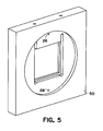
- FIG. 4 An alternate embodiment of the apparatus of the present invention is partially illustrated in Figure 4.
- This embodiment comprised a Peltier effect solid-state heat pump (not shown) surrounded by a polycarbonate frame 50 which created a cavity on each side of the heat pump.
- the cavities were filled with a deliquescent solution and covered with membrane. Apertures 26, 28 through the frame 50 permit circulation of the deliquescent solution between the cavities.
- the apparatus of this example comprised the following components:
Landscapes
- Chemical & Material Sciences (AREA)
- Engineering & Computer Science (AREA)
- Analytical Chemistry (AREA)
- General Chemical & Material Sciences (AREA)
- Oil, Petroleum & Natural Gas (AREA)
- Chemical Kinetics & Catalysis (AREA)
- Physics & Mathematics (AREA)
- Thermal Sciences (AREA)
- Drying Of Gases (AREA)
- Separation Using Semi-Permeable Membranes (AREA)
Applications Claiming Priority (2)
| Application Number | Priority Date | Filing Date | Title |
|---|---|---|---|
| US514125 | 1995-08-11 | ||
| US08/514,125 US5575835A (en) | 1995-08-11 | 1995-08-11 | Apparatus for removing moisture from an environment |
Publications (1)
| Publication Number | Publication Date |
|---|---|
| EP0758730A2 true EP0758730A2 (fr) | 1997-02-19 |
Family
ID=24045907
Family Applications (1)
| Application Number | Title | Priority Date | Filing Date |
|---|---|---|---|
| EP96305847A Withdrawn EP0758730A2 (fr) | 1995-08-11 | 1996-08-09 | Dispositif pour l'élimination d'humidité d'un environnement |
Country Status (3)
| Country | Link |
|---|---|
| US (1) | US5575835A (fr) |
| EP (1) | EP0758730A2 (fr) |
| JP (1) | JPH09117637A (fr) |
Cited By (1)
| Publication number | Priority date | Publication date | Assignee | Title |
|---|---|---|---|---|
| WO2003014629A1 (fr) | 2001-08-10 | 2003-02-20 | Aloys Wobben | Installation d'energie eolienne |
Families Citing this family (24)
| Publication number | Priority date | Publication date | Assignee | Title |
|---|---|---|---|---|
| WO2004098752A1 (fr) * | 1994-10-13 | 2004-11-18 | Kunitaka Mizobe | Systeme deshumidificateur |
| JP4121165B2 (ja) * | 1995-12-28 | 2008-07-23 | 株式会社九州山光社 | 分離モジュール |
| US6378311B1 (en) * | 2000-05-18 | 2002-04-30 | Raytheon Company | Thermoelectric dehumidifier |
| DE10059910C2 (de) * | 2000-12-01 | 2003-01-16 | Daimler Chrysler Ag | Vorrichtung zur kontinuierlichen Befeuchtung und Entfeuchtung der Zuluft von Fertigungsprozessen oder Raumlufttechnik-Anlagen |
| US6497749B2 (en) * | 2001-03-30 | 2002-12-24 | United Technologies Corporation | Dehumidification process and apparatus using collodion membrane |
| DE10141897C1 (de) * | 2001-08-28 | 2003-04-17 | Interpane Entw & Beratungsges | System mit Verglasungselement und Gasversorgungsvorrichtung |
| US6470696B1 (en) * | 2001-09-18 | 2002-10-29 | Valerie Palfy | Devices and methods for sensing condensation conditions and for removing condensation from surfaces |
| BE1015424A3 (nl) * | 2003-03-21 | 2005-03-01 | Beken Carine V D | Laagvermogen luchtdroger voor kasten met actieve en passieve elektrische en optische componenten. |
| US7403135B1 (en) * | 2003-12-22 | 2008-07-22 | Daktronics, Inc. | Capacitive relay takeoff swimming platform sensor system |
| US7624788B2 (en) * | 2004-04-22 | 2009-12-01 | State Of Oregon Acting By And Through The State Board Of Higher Education On Behalf Of The University Of Oregon | Heat exchanger |
| DE102005060673A1 (de) * | 2005-12-19 | 2007-06-21 | BSH Bosch und Siemens Hausgeräte GmbH | Wäschetrockner mit Peltier-Wärmepumpe |
| US20070151447A1 (en) * | 2005-12-30 | 2007-07-05 | Membrane Technology And Research, Inc. | Gas separation membranes and processes for controlled environmental management |
| US20110030388A1 (en) * | 2006-09-01 | 2011-02-10 | Mikael Johansson | Humidity control of an electrical device |
| US7751980B2 (en) * | 2006-12-22 | 2010-07-06 | Schlumberger Technology Corporation | Method and apparatus for evaluating elastic mechanical properties of a transversely isotropic formation |
| EP2126351B1 (fr) * | 2007-01-31 | 2014-05-07 | Vestas Wind Systems A/S | Convertisseur d'énergie éolienne avec déshumidificateur |
| US8984897B2 (en) * | 2009-09-16 | 2015-03-24 | International Business Machines Corporation | Endothermic reaction apparatus for removing excess heat in a datacenter |
| DE102009054921B4 (de) * | 2009-12-18 | 2020-09-03 | Robert Bosch Gmbh | Verfahren und Vorrichtung zur Minderung der Feuchtigkeit eines Gases in einem Batteriegehäuseinnenraum |
| CN101879400B (zh) * | 2010-06-30 | 2013-10-23 | 南车株洲电力机车研究所有限公司 | 一种风力发电系统变流装置的空气除湿方法及除湿系统 |
| DE102010050042A1 (de) * | 2010-10-29 | 2012-05-03 | Aaa Water Technologies Ag | Vorrichtung zum Trocknen und/oder Kühlen von Gas |
| WO2014210157A1 (fr) * | 2013-06-25 | 2014-12-31 | 3M Innovative Properties Company | Panneaux de transfert de chaleur et de masse à déshydratant liquide souples |
| WO2015161030A1 (fr) * | 2014-04-17 | 2015-10-22 | Magna Mirrors Of America, Inc. | Fenêtre de véhicule à store |
| US10143763B2 (en) | 2016-10-06 | 2018-12-04 | Alfonso Campalans | Neutral atmosphere and sanitization storage apparatus, method and system |
| KR101989993B1 (ko) * | 2016-11-10 | 2019-09-30 | 엘지전자 주식회사 | 공기조화기장치 |
| KR101989994B1 (ko) * | 2016-11-10 | 2019-09-30 | 엘지전자 주식회사 | 공기조화기장치 |
Family Cites Families (39)
| Publication number | Priority date | Publication date | Assignee | Title |
|---|---|---|---|---|
| US1738720A (en) * | 1925-12-02 | 1929-12-10 | Electrolux Servel Corp | Refrigeration |
| DE523114C (de) * | 1929-01-01 | 1931-04-23 | I G Farbenindustrie Akt Ges | Trennung von Gasgemischen mit Hilfe eines dampffoermigen Diffusionsmittels |
| US2433741A (en) * | 1943-02-13 | 1947-12-30 | Robert B P Crawford | Chemical dehumidifying method and means |
| US2506656A (en) * | 1945-10-15 | 1950-05-09 | George S Hills | Air conditioner |
| FR1065268A (fr) * | 1951-06-14 | 1954-05-21 | Chemie Linz Ag | Procédé de séparation de constituants de mélanges gazeux par diffusion |
| US3248861A (en) * | 1963-07-29 | 1966-05-03 | Charles L Lovercheck | Dehumidifier |
| US3447286A (en) * | 1967-08-02 | 1969-06-03 | Gen Electric | Totally enclosed liquid permselective membrane |
| US3488971A (en) * | 1968-04-29 | 1970-01-13 | Gershon Meckler | Comfort conditioning system |
| US3676220A (en) * | 1969-02-27 | 1972-07-11 | Gen Electric | Facilitated transport liquid membrane |
| CA962021A (en) * | 1970-05-21 | 1975-02-04 | Robert W. Gore | Porous products and process therefor |
| US3911080A (en) * | 1971-09-10 | 1975-10-07 | Wright H Dudley | Air pollution control |
| DE2446871A1 (de) * | 1974-10-01 | 1976-05-20 | Otto Eigner | Rationelle waermepumpe |
| JPS537578A (en) * | 1976-07-09 | 1978-01-24 | Oval Eng Co Ltd | Apparatus and method for treating gases |
| US4110392A (en) * | 1976-12-17 | 1978-08-29 | W. L. Gore & Associates, Inc. | Production of porous sintered PTFE products |
| US4430864A (en) * | 1981-12-31 | 1984-02-14 | Midwest Research Institute | Hybrid vapor compression and desiccant air conditioning system |
| GB2126706B (en) * | 1982-09-03 | 1986-02-05 | Exxon Research Engineering Co | Combined adsorption and absorption heat pump |
| US4528078A (en) * | 1984-05-23 | 1985-07-09 | The United States Of America As Represented By The United States Department Of Energy | Nonsaturable microdryer |
| JPS61129019A (ja) * | 1984-11-26 | 1986-06-17 | Hitachi Ltd | 吸収式温度回生器 |
| US4750918A (en) * | 1985-05-28 | 1988-06-14 | The Trustees Of The Stevens Institute Of Technology | Selective-permeation gas-separation process and apparatus |
| BE904140A (fr) * | 1986-01-30 | 1986-07-30 | Solvay | Appareil pour la dessication d'air humide. |
| NL8702150A (nl) * | 1987-09-09 | 1989-04-03 | Tno | Werkwijze en membraan voor het door middel van damppermeatie verwijderen van waterdamp uit een gas-damp-mengsel. |
| JPH0199631A (ja) * | 1987-10-13 | 1989-04-18 | Shirakawa Seisakusho:Kk | 除湿機 |
| JPH01148307A (ja) * | 1987-12-02 | 1989-06-09 | Hitachi Ltd | 膜蒸留装置 |
| JPH01297122A (ja) * | 1988-01-14 | 1989-11-30 | Choichi Furuya | 疎水性細孔膜を有する気体分離装置 |
| EP0326083B1 (fr) * | 1988-01-26 | 1994-06-01 | Asahi Glass Company Ltd. | Membrane permseléctif de vapeur |
| JPH01194927A (ja) * | 1988-01-27 | 1989-08-04 | Japan Gore Tex Inc | 水蒸気選択透過膜 |
| US4915838A (en) * | 1988-03-29 | 1990-04-10 | Honeywell Inc. | Membrane dehumidification |
| US4900448A (en) * | 1988-03-29 | 1990-02-13 | Honeywell Inc. | Membrane dehumidification |
| US4862730A (en) * | 1988-10-03 | 1989-09-05 | W. L. Gore & Associates, Inc. | Test method for determination of moisture vapor transmission rate |
| US5108464A (en) * | 1989-09-19 | 1992-04-28 | Bend Research, Inc. | Countercurrent dehydration by hollow fibers |
| US5002590A (en) * | 1989-09-19 | 1991-03-26 | Bend Research, Inc. | Countercurrent dehydration by hollow fibers |
| NL9000783A (nl) * | 1990-04-03 | 1991-11-01 | Tno | Membraanscheidingsproces voor het door pervaporatie, damppermeatie of gasscheiding ontwateren van een gas- of damp- of vloeistofmengsel. |
| JPH04187218A (ja) * | 1990-11-21 | 1992-07-03 | Hitachi Ltd | 塩類を含む溶液の処理方法及びその装置 |
| US5236474A (en) * | 1991-09-13 | 1993-08-17 | Bend Research, Inc. | Membrane-based removal of condensable vapors |
| US5281254A (en) * | 1992-05-22 | 1994-01-25 | United Technologies Corporation | Continuous carbon dioxide and water removal system |
| JP2867800B2 (ja) * | 1992-06-26 | 1999-03-10 | ダイキン工業株式会社 | 液体通路およびパネル |
| JPH06106021A (ja) * | 1992-09-28 | 1994-04-19 | Nitto Denko Corp | 膜型吸収式除湿器 |
| JP3132940B2 (ja) * | 1993-03-02 | 2001-02-05 | 松下電器産業株式会社 | 加湿機能付空気調和機 |
| GB2280744A (en) * | 1993-08-03 | 1995-02-08 | Isoterix Ltd | Inverted heatpipes |
-
1995
- 1995-08-11 US US08/514,125 patent/US5575835A/en not_active Expired - Fee Related
-
1996
- 1996-08-09 EP EP96305847A patent/EP0758730A2/fr not_active Withdrawn
- 1996-08-09 JP JP8211607A patent/JPH09117637A/ja active Pending
Cited By (4)
| Publication number | Priority date | Publication date | Assignee | Title |
|---|---|---|---|---|
| WO2003014629A1 (fr) | 2001-08-10 | 2003-02-20 | Aloys Wobben | Installation d'energie eolienne |
| DE10139556A1 (de) * | 2001-08-10 | 2003-02-27 | Aloys Wobben | Einrichtung zur Entfeuchtung eines gasförmigen Mediums und Windenergieanlage mit einer solchen Einrichtung |
| US7874165B2 (en) | 2001-08-10 | 2011-01-25 | Aloys Wobben | Wind power installation |
| US7886546B2 (en) | 2001-08-10 | 2011-02-15 | Aloys Wobben | Wind power installation |
Also Published As
| Publication number | Publication date |
|---|---|
| US5575835A (en) | 1996-11-19 |
| JPH09117637A (ja) | 1997-05-06 |
Similar Documents
| Publication | Publication Date | Title |
|---|---|---|
| US5575835A (en) | Apparatus for removing moisture from an environment | |
| US11719447B2 (en) | Cooling systems having an integrated ionic liquid salt dehumidification system | |
| US5528905A (en) | Contactor, particularly a vapour exchanger for the control of the air hygrometric content, and a device for air handling | |
| US6539731B2 (en) | Dehumidification process and apparatus | |
| US20040211207A1 (en) | Apparatus for conditioning air | |
| US4377398A (en) | Heat energized vapor adsorbent pump | |
| US11976445B2 (en) | Atmospheric water generation method and device | |
| US4165952A (en) | Heat energized vapor adsorbent pump | |
| JP2006529022A (ja) | 熱吸収用熱力学的装置および方法 | |
| WO2008084528A1 (fr) | Appareil réfrigérant | |
| JP2014525558A (ja) | 乾燥剤ベースの冷房システム | |
| US6453679B1 (en) | Dehumidifier and control system for a disk drive | |
| Papadakis et al. | CORRELATIONS FOR THE EQUILIBRIUM MOISTURE CONTENT OF SOI. IDS | |
| US5092135A (en) | Air conditioning system | |
| Brillhart | Evaluation of desiccant rotor matrices using an advanced fixed-bed test system | |
| JP4122271B2 (ja) | 調湿セルおよび高感度ガスセンサ | |
| US20160256821A1 (en) | Versatile dehumidification process and apparatus using a hydrophobic membrane | |
| JP4792829B2 (ja) | 調湿装置 | |
| JPH06121910A (ja) | 湿度調整器 | |
| Izenson et al. | Design, development, and testing of a water vapor exchanger for spacecraft life support systems | |
| Alberti | Theoretical and experimental analysis of a solid adsorption dehumidifier for solar DEC systems | |
| Stewart Jr | Effect of air pressure differential on vapor flow through sampler building walls | |
| Izenson et al. | Nonventing thermal and humidity control for EVA suits | |
| JPH06201231A (ja) | 冷媒中の水分除去装置 | |
| Ventrapragada et al. | Integration of a Desiccant Dehumidification System with a Fuel Cell System for Distributed Power Generation and Waste Heat Recovery |
Legal Events
| Date | Code | Title | Description |
|---|---|---|---|
| PUAI | Public reference made under article 153(3) epc to a published international application that has entered the european phase |
Free format text: ORIGINAL CODE: 0009012 |
|
| AK | Designated contracting states |
Kind code of ref document: A2 Designated state(s): DE ES FR GB IT SE |
|
| STAA | Information on the status of an ep patent application or granted ep patent |
Free format text: STATUS: THE APPLICATION IS DEEMED TO BE WITHDRAWN |
|
| 18D | Application deemed to be withdrawn |
Effective date: 19990302 |