EP0758735A2 - Pyrotechnischer Zünder und Verfahren zu dessen Herstellung - Google Patents
Pyrotechnischer Zünder und Verfahren zu dessen Herstellung Download PDFInfo
- Publication number
- EP0758735A2 EP0758735A2 EP96305893A EP96305893A EP0758735A2 EP 0758735 A2 EP0758735 A2 EP 0758735A2 EP 96305893 A EP96305893 A EP 96305893A EP 96305893 A EP96305893 A EP 96305893A EP 0758735 A2 EP0758735 A2 EP 0758735A2
- Authority
- EP
- European Patent Office
- Prior art keywords
- stranded wire
- free end
- length
- wire
- torch
- Prior art date
- Legal status (The legal status is an assumption and is not a legal conclusion. Google has not performed a legal analysis and makes no representation as to the accuracy of the status listed.)
- Withdrawn
Links
- 239000003999 initiator Substances 0.000 title claims abstract description 56
- 238000000034 method Methods 0.000 title claims abstract description 37
- 230000008569 process Effects 0.000 title claims abstract description 31
- 238000003466 welding Methods 0.000 claims abstract description 17
- 239000004020 conductor Substances 0.000 claims description 16
- 238000009413 insulation Methods 0.000 claims description 7
- 238000003825 pressing Methods 0.000 claims 3
- 238000007689 inspection Methods 0.000 abstract description 8
- WABPQHHGFIMREM-UHFFFAOYSA-N lead(0) Chemical compound [Pb] WABPQHHGFIMREM-UHFFFAOYSA-N 0.000 description 28
- 239000002184 metal Substances 0.000 description 9
- 229910052751 metal Inorganic materials 0.000 description 9
- 239000007789 gas Substances 0.000 description 6
- RYGMFSIKBFXOCR-UHFFFAOYSA-N Copper Chemical compound [Cu] RYGMFSIKBFXOCR-UHFFFAOYSA-N 0.000 description 4
- 238000011179 visual inspection Methods 0.000 description 3
- XKRFYHLGVUSROY-UHFFFAOYSA-N Argon Chemical compound [Ar] XKRFYHLGVUSROY-UHFFFAOYSA-N 0.000 description 2
- 230000015572 biosynthetic process Effects 0.000 description 2
- 239000011521 glass Substances 0.000 description 2
- 210000001503 joint Anatomy 0.000 description 2
- 238000004519 manufacturing process Methods 0.000 description 2
- 238000012986 modification Methods 0.000 description 2
- 230000004048 modification Effects 0.000 description 2
- 239000004593 Epoxy Substances 0.000 description 1
- 230000003064 anti-oxidating effect Effects 0.000 description 1
- 229910052786 argon Inorganic materials 0.000 description 1
- 230000000712 assembly Effects 0.000 description 1
- 238000000429 assembly Methods 0.000 description 1
- 239000011324 bead Substances 0.000 description 1
- 230000006835 compression Effects 0.000 description 1
- 238000007906 compression Methods 0.000 description 1
- 229910052802 copper Inorganic materials 0.000 description 1
- 239000010949 copper Substances 0.000 description 1
- 238000010304 firing Methods 0.000 description 1
- 239000000463 material Substances 0.000 description 1
- 239000000155 melt Substances 0.000 description 1
- 238000004382 potting Methods 0.000 description 1
- 230000009467 reduction Effects 0.000 description 1
- 230000001629 suppression Effects 0.000 description 1
- 229910000859 α-Fe Inorganic materials 0.000 description 1
Images


Classifications
-
- F—MECHANICAL ENGINEERING; LIGHTING; HEATING; WEAPONS; BLASTING
- F42—AMMUNITION; BLASTING
- F42B—EXPLOSIVE CHARGES, e.g. FOR BLASTING, FIREWORKS, AMMUNITION
- F42B3/00—Blasting cartridges, i.e. case and explosive
- F42B3/10—Initiators therefor
- F42B3/195—Manufacture
Definitions
- This invention relates generally to electrically activated pyrotechnic initiators of the kind used in the deployment of automotive airbags. It relates more particularly to improvements in the electrical connections by which an electrical signal is conducted from a source of electrical power to the initiator.
- Airbag specifications generally require very flexible leadwires, typically 18 or 20 gauge, insulated, stranded wire.
- leadwire typically 41 strands of extremely fine copper wire, each having a diameter of 0.004 inch.
- a major difficulty in making connections of these fine, stranded leadwires to initiator terminals arises because of the tendency of the stranded wire to fray, and because of the small size and close spacing of electrical terminals within the initiator.
- a single loose strand can cause a short circuit either from one wire to the other, or from one wire to a metal portion of the initiator case.
- One method is to utilize an intermediate component such as a wire terminal, clasp or sleeve to gather the strands of wire together either prior to, or after, the attachment of the lead to the initiator terminal.
- This approach has several disadvantages. It requires an additional component and additional, difficult assembly steps. It also requires additional internal space in the initiator, which may necessitate an increase in the overall size of the initiator. Furthermore, it requires inspection, which is difficult to carry out and may disturb the electrical connections.
- Another approach is to utilize wire strand capturing geometry in the initiator or attachment tooling. This approach also has disadvantages in that it increases the cost of the initiator components, and requires extra processing and inspections. It is not entirely effective in preventing fraying and consequent short-circuiting.
- the length of the stripped portion of the wire can be kept as short as possible to minimize the potential of the strands of the wire to fray.
- the disadvantage of this approach is that there is a minimum stripped length required for attachment of the wire to the initiator terminal.
- the tolerance necessary to assure reliable connections in spite of possible errors in the connection process must be added to the absolute minimum stripped length. When the tolerance is added, there is still enough stripped length that there is a significant possibility of fraying.
- Still another approach is to use a butt joint rather than a lap joint. This will avoid lateral compression of the bundle of strands in the wire, and thereby reduce the potential of the wire to fray.
- the butt joint technique requires very accurate location of the wire relative to the initiator terminal and, for that reason is not entirely satisfactory.
- the principal objects of this invention are to provide a highly reliable and inexpensive method for making connections of fine stranded wire to initiator terminals, and to provide an inexpensive and reliable initiator, free of loose strands which may cause a short circuit.
- a pyrotechnic initiator is made by a process in which the tips of the strands of a length of stranded wire are fused together to form a ball at a free end of the wire. The free end is then welded to an electrical conductor of the initiator. This process prevents fraying of the stranded wire in the process of attaching it to the initiator, and avoids short circuits, thereby producing a more reliable initiator.
- the fusing step is carried out by means of a plasma arc.
- a short length of insulation is stripped from insulated, stranded wire to expose a short length of the stranded wire having a free end.
- This short length of exposed wire is held in an electrically conductive clamp, with the free end extending beyond the clamp.
- a plasma torch is brought into proximity to the free end of the length of stranded wire, and an electrical arc is struck from the plasma torch to the free end of wire by imposing an electrical potential difference on the clamp and torch.
- a plasma gas and a shielding gas are passed through the torch.
- the ball formed at the end of the wire by the fusing of the ends of the strands together is then pressed by a welding electrode against a terminal of the initiator, which may be either a pin, or a portion of the initiator body.
- the pressure tends to flatten the ball while welding takes place. This process produces a good electrical connection of the wire to the initiator terminal, but cannot cause fraying of the wire.
- the process can be carried out with minimal inspection, and produces a highly reliable product at a very low cost.
- the initiator 10 shown in FIG. 1, comprises a metal squib body 12 to which is attached a cup 14 containing a pyrotechnic charge 16.
- a central terminal pin 18, having a flattened end 20, extends axially through the squib body, from the pyrotechnic charge 16, where it is supported by glass insulation 22.
- a ferrite bead 24 surrounds pin 18 for r.f. suppression.
- a bridge wire (not shown) is connected from the end of pin 18 to the metal squib body 12 in the vicinity of the pyrotechnic charge. When heated by an electric current, the bridge wire sets off the charge 16.
- the squib body 12 is supported in a retainer 26 having a mounting flange 28.
- the squib body is surrounded by a metal ring 30 and separated from the metal ring by a ring 32 of insulating glass.
- the cup 14 is enclosed within an elongated insulating cup 34, which is held in a sleeve 36, crimped into retainer 26.
- leads 38 and 40 Electric current is conducted to the device through leads 38 and 40. These leads are insulated, stranded wire.
- the stranded conductor in each lead typically consists of 41 strands of extremely fine copper wire, each having a diameter of 0.004 inch.
- the insulation is stripped from one end of the lead 38 to expose a short length of conductor at 42, which is welded to the flat end 20 of central pin 18.
- One end of lead 40 is similarly stripped to expose a short length of conductor at 44, which is welded to the outside of squib body 12.
- Both leads are potted in epoxy potting material 46, and the far ends of the leads are stripped and temporarily twisted together at 48 as a safety measure to avoid accidental firing of the pyrotechnic charge by stray fields.
- a typical assembly of the kind shown in FIG. 1 is only about one inch in length, with the diameter of the insulating cup being less than one-half inch. Some initiator assemblies are even smaller.
- the small size, and the requirement for fine, stranded leadwires leads to the possibility of short-circuiting in conventional initiators, and has required careful measures to avoid short-circuiting, as discussed above.
- balls are formed at the ends of the leadwires by a plasma arc.
- the ends of the leadwires can then be pressed against the central pin and squib body respectively in the subsequent attachment process without fraying. This eliminates the need for careful inspection, and results in an initiator of consistent quality with few rejects in the final inspection.
- the formation of the balls at the ends of the leadWires is carried out by a plasma arc torch 50 as shown in FIG. 2.
- the plasma arc torch also known as a "PAW" (Plasma Arc Welder) torch, is used to direct a short duration electrical arc from an electrode (not shown) in the torch to the end of the leadwire. Details of a typical plasma arc torch are described in United States Patent 5,013,885, dated May 7, 1991. The specification and drawings of Patent 5,013,885 are here incorporated by reference.
- the torch 50 is mounted on an arm 52 so that it can be accurately moved in three dimensions by a suitable positioning device (not shown).
- the exposed conductor 42 at the stripped end of leadwire 38 is clamped between the edges of a pair of metal clamping plates, one of which is shown at 54 in FIG. 2. These plates are secured to metal supports which are movable toward each other in order to bring the edges of the metal plates together.
- One such support is shown in FIG. 2 at 56.
- the other metal plate 57, and the other support 59 are similar to plate 54 and support 56, and are illustrated in FIG. 3. Support 56 is stationary, while support 57 is pivoted so that the edges of plates 54 and 59 can be brought together to clamp the exposed conductor 42.
- Plate 54 has a recess 58, and plate 59 has a similar recess 61. These recesses come together to form a single recess receiving the end of the insulated portion of leadwire 38.
- the end of the leadwire stripped to a predetermined length when the end of the insulation abuts the wall 60 of recess 58 and wall 63 of recess 61, the end of the conductor of the leadwire is positioned at a predetermined location in the Z axis, i.e. along the direction of the length of the lead wire.
- the vertical position, or Y axis position, of the end of the leadwire is determined by aligning the wire with a suitable marking on the clamping plates.
- the Y axis position can be determined by a suitable support for the wire, or by positioning the wire in a small recess in an edge one of the plates.
- the X position of the end of the wire is determined by the edges of the clamping plates themselves, since, with one of the supports, e.g. support 56, fixed, the edges can be brought together at a single predetermined position. With the leadwire clamped between the edges of the clamping plates, its end is therefore held at a predetermined location. The tip of the plasma torch can then be brought to a predetermined position without reference to the location of the end of the leadwire, and the tip of the plasma torch will be directly opposite to the end of the leadwire.
- the supports for the clamping plates are connected to one pole of the torch power supply, while the electrode of the torch is connected to the other pole.
- the clamping plates and their supports conduct electric current to the exposed portion 42 of the leadwire.
- an electrical arc is struck between the torch electrode and the tip of the leadwire.
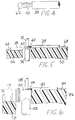
- Auxiliary systems are provided to control current and timing, and to direct plasma supporting gas and anti-oxidation gas through the torch. The heat generated by the arc melts the end of the wire, and, as the molten copper coalesces and cools, a ball 62 is formed at the end of the wire, as shown in FIG. 4.
- the plasma arc conditions are as follows.
- the plasma current is held at 16.0 amperes for a duration of 0.4 seconds.
- the plasma gas flow is 0.4 liters per minute, and the shielding gas (Argon) flow is 6 liters per minute.
- the current is raised to 20.0 amperes, with the other conditions remaining the same.
- the ball 62 permanently secures the ends of the individual strands of copper wire together, so that they wire cannot fray in the process of connecting it to the terminals of the initiator.
- the exposed portion 42 of leadwire 38 is secured to the flat portion 20 of terminal pin 18 by spot welding.
- the pin 18 supported in a groove 64 on the top surface of an insulating block 66, and the leadwire is similarly supported in a groove 68 on the top surface of an insulating block 70.
- Spot welding electrodes 72 and 74 are brought toward each other and the exposed portion 42 of the wire and the flat portion 20 of the terminal pin 18 are clamped together between the welding electrodes.
- An electrical potential difference is applied to electrodes 72 and 74, and the resulting heavy, localized current in the parts of the wire and pin compressed between the electrodes causes the wire to be securely welded to the pin.
- the other leadwire, 40 is welded to the squib body 12 in a similar manner, as shown in FIG. 6.
- the squib body is supported in a groove 76 formed in the top surface of insulating block 78.
- the cylindrical portion 80 of the squib body is supported by a lower spot welding electrode 82 having, at its upper end, a groove for receiving portion 80 of the squib body.
- Leadwire 40 is supported in a groove 84 on the upper surface of insulating block 86.
- the two insulating blocks are so related to each other that the exposed length 44 of the conductor of leadwire 40 lies against the cylindrical portion 80 of the squib body underneath an upper spot welding electrode 88.
- the spot welding electrodes are brought toward each other, and part of the exposed length 44 of the lead wire is compressed against the squib body in the spot welding process.
- the pressure applied to the wire by the welding electrodes must be sufficient to produce a good weld, and is therefore also sufficient to flatten the wire. However, because the ends of the individual strands of the leadwire are fused together into a ball, the pressure of the welding electrodes cannot cause fraying of the wire.
- process of the invention has particular utility in the manufacture of airbag initiators, the process can be used in other miniature, electrically actuated pyrotechnic devices in which fraying of stranded wire could cause short circuiting.
Landscapes
- Engineering & Computer Science (AREA)
- Manufacturing & Machinery (AREA)
- General Engineering & Computer Science (AREA)
- Air Bags (AREA)
- Manufacturing Of Electrical Connectors (AREA)
- Wire Processing (AREA)
Applications Claiming Priority (2)
| Application Number | Priority Date | Filing Date | Title |
|---|---|---|---|
| US51461695A | 1995-08-14 | 1995-08-14 | |
| US514616 | 1995-08-14 |
Publications (2)
| Publication Number | Publication Date |
|---|---|
| EP0758735A2 true EP0758735A2 (de) | 1997-02-19 |
| EP0758735A3 EP0758735A3 (de) | 1998-01-07 |
Family
ID=24047977
Family Applications (1)
| Application Number | Title | Priority Date | Filing Date |
|---|---|---|---|
| EP96305893A Withdrawn EP0758735A3 (de) | 1995-08-14 | 1996-08-12 | Pyrotechnischer Zünder und Verfahren zu dessen Herstellung |
Country Status (1)
| Country | Link |
|---|---|
| EP (1) | EP0758735A3 (de) |
Citations (1)
| Publication number | Priority date | Publication date | Assignee | Title |
|---|---|---|---|---|
| US5013885A (en) | 1990-02-28 | 1991-05-07 | Esab Welding Products, Inc. | Plasma arc torch having extended nozzle of substantially hourglass |
Family Cites Families (6)
| Publication number | Priority date | Publication date | Assignee | Title |
|---|---|---|---|---|
| SE378139B (de) * | 1973-11-27 | 1975-08-18 | Bofors Ab | |
| CH616774A4 (de) * | 1976-04-09 | 1975-12-31 | ||
| US4489231A (en) * | 1980-09-19 | 1984-12-18 | Teltec Inc. | Method for preparing electrical conductor |
| DE3567268D1 (en) * | 1984-01-31 | 1989-02-09 | Dynamit Nobel Ag | Electric ignitor |
| EP0375458B1 (de) * | 1988-12-22 | 1995-06-14 | Molex Incorporated | Leiterentmantelung und -abschluss in Multiaderkabeln |
| DE3915286A1 (de) * | 1989-05-10 | 1990-11-15 | August Maertens Gmbh & Co Kg | Vorrichtung zum automatischen abisolieren und verschweissen von aderleitungen |
-
1996
- 1996-08-12 EP EP96305893A patent/EP0758735A3/de not_active Withdrawn
Patent Citations (1)
| Publication number | Priority date | Publication date | Assignee | Title |
|---|---|---|---|---|
| US5013885A (en) | 1990-02-28 | 1991-05-07 | Esab Welding Products, Inc. | Plasma arc torch having extended nozzle of substantially hourglass |
Also Published As
| Publication number | Publication date |
|---|---|
| EP0758735A3 (de) | 1998-01-07 |
Similar Documents
| Publication | Publication Date | Title |
|---|---|---|
| US5877472A (en) | System for laser-welding components of an implantable device | |
| JP3975201B2 (ja) | ケーブル | |
| EP2192601B1 (de) | Kabelbaum und verfahren zu seiner herstellung | |
| EP0261905B1 (de) | Elektrischer Verbinder und Verfahren zur Verbindung von Adern an diesem | |
| JPH09161936A (ja) | 線材の接合方法 | |
| US4922072A (en) | Wire connecting method | |
| US4396819A (en) | Method of forming a conductive connection | |
| JPH0684547A (ja) | 圧着端子の加工方法及びその装置 | |
| US4964210A (en) | Method of connecting stator coil of motor | |
| CN114597686A (zh) | 接线端子、电机以及接线方法 | |
| US5451736A (en) | Welding process for connecting a winding wire of a coil to a terminal and metal sleeve for use in this process | |
| JP2009123451A (ja) | 電線と端子のスポット溶接方法 | |
| GB2086297A (en) | Method of Forming a Wire Bond | |
| IE53452B1 (en) | Electrical plug connector | |
| EP0758735A2 (de) | Pyrotechnischer Zünder und Verfahren zu dessen Herstellung | |
| EP0585786B1 (de) | Verfahren zum Herstellen einer Rücklauftransformator | |
| US7568276B2 (en) | Apparatus for producing an inductor | |
| US1685382A (en) | Method of bridging the connecting wires of electric blasting caps | |
| US4489231A (en) | Method for preparing electrical conductor | |
| CA1104692A (en) | Electrical connector contact comprising a plurality of wires and method of making it | |
| JPH09161937A (ja) | 端子と電線の接続方法 | |
| US4242790A (en) | Method of making an electrical connector contact | |
| US20220395692A1 (en) | In Situ Welding for Feedthrough Pad Attachment | |
| JPH0982447A (ja) | 電線接続方法 | |
| CN115020994B (zh) | 编织部件连接结构 |
Legal Events
| Date | Code | Title | Description |
|---|---|---|---|
| PUAI | Public reference made under article 153(3) epc to a published international application that has entered the european phase |
Free format text: ORIGINAL CODE: 0009012 |
|
| AK | Designated contracting states |
Kind code of ref document: A2 Designated state(s): DE FR GB |
|
| PUAL | Search report despatched |
Free format text: ORIGINAL CODE: 0009013 |
|
| AK | Designated contracting states |
Kind code of ref document: A3 Designated state(s): DE FR GB |
|
| STAA | Information on the status of an ep patent application or granted ep patent |
Free format text: STATUS: THE APPLICATION IS DEEMED TO BE WITHDRAWN |
|
| 18D | Application deemed to be withdrawn |
Effective date: 19980708 |