EP0758753A2 - Diffraktive optische Elemente - Google Patents
Diffraktive optische Elemente Download PDFInfo
- Publication number
- EP0758753A2 EP0758753A2 EP96112472A EP96112472A EP0758753A2 EP 0758753 A2 EP0758753 A2 EP 0758753A2 EP 96112472 A EP96112472 A EP 96112472A EP 96112472 A EP96112472 A EP 96112472A EP 0758753 A2 EP0758753 A2 EP 0758753A2
- Authority
- EP
- European Patent Office
- Prior art keywords
- lens
- zones
- temperature
- diffractive
- doe
- Prior art date
- Legal status (The legal status is an assumption and is not a legal conclusion. Google has not performed a legal analysis and makes no representation as to the accuracy of the status listed.)
- Withdrawn
Links
- 230000003287 optical effect Effects 0.000 title claims abstract description 23
- 230000003247 decreasing effect Effects 0.000 claims abstract description 5
- 230000010363 phase shift Effects 0.000 claims abstract 2
- 238000013461 design Methods 0.000 claims description 16
- 239000000463 material Substances 0.000 claims description 9
- 238000000034 method Methods 0.000 claims description 9
- 230000007423 decrease Effects 0.000 claims description 5
- 238000004519 manufacturing process Methods 0.000 claims description 5
- 230000004075 alteration Effects 0.000 abstract description 16
- 230000000694 effects Effects 0.000 abstract description 3
- 238000012935 Averaging Methods 0.000 abstract description 2
- 238000007516 diamond turning Methods 0.000 abstract 1
- 238000001746 injection moulding Methods 0.000 abstract 1
- 230000008602 contraction Effects 0.000 description 7
- 230000008859 change Effects 0.000 description 5
- 201000009310 astigmatism Diseases 0.000 description 4
- 238000003384 imaging method Methods 0.000 description 4
- 206010010071 Coma Diseases 0.000 description 2
- 230000008901 benefit Effects 0.000 description 2
- 238000010276 construction Methods 0.000 description 2
- 238000012937 correction Methods 0.000 description 2
- 230000005499 meniscus Effects 0.000 description 2
- 238000005457 optimization Methods 0.000 description 2
- 230000000717 retained effect Effects 0.000 description 2
- 230000003190 augmentative effect Effects 0.000 description 1
- 230000015556 catabolic process Effects 0.000 description 1
- 239000002131 composite material Substances 0.000 description 1
- 238000004590 computer program Methods 0.000 description 1
- 238000007596 consolidation process Methods 0.000 description 1
- 230000001595 contractor effect Effects 0.000 description 1
- 238000007796 conventional method Methods 0.000 description 1
- 238000006731 degradation reaction Methods 0.000 description 1
- 229910003460 diamond Inorganic materials 0.000 description 1
- 239000010432 diamond Substances 0.000 description 1
- 238000009826 distribution Methods 0.000 description 1
- 229910052732 germanium Inorganic materials 0.000 description 1
- GNPVGFCGXDBREM-UHFFFAOYSA-N germanium atom Chemical compound [Ge] GNPVGFCGXDBREM-UHFFFAOYSA-N 0.000 description 1
- 239000011521 glass Substances 0.000 description 1
- 238000012423 maintenance Methods 0.000 description 1
- 238000005259 measurement Methods 0.000 description 1
- 238000012986 modification Methods 0.000 description 1
- 230000004048 modification Effects 0.000 description 1
- 229920003023 plastic Polymers 0.000 description 1
- 239000004033 plastic Substances 0.000 description 1
- 230000004044 response Effects 0.000 description 1
- 238000000926 separation method Methods 0.000 description 1
- 238000001228 spectrum Methods 0.000 description 1
- 238000002849 thermal shift Methods 0.000 description 1
- 238000012546 transfer Methods 0.000 description 1
- 230000009466 transformation Effects 0.000 description 1
- 238000000844 transformation Methods 0.000 description 1
Images





Classifications
-
- G—PHYSICS
- G02—OPTICS
- G02B—OPTICAL ELEMENTS, SYSTEMS OR APPARATUS
- G02B5/00—Optical elements other than lenses
- G02B5/18—Diffraction gratings
- G02B5/1876—Diffractive Fresnel lenses; Zone plates; Kinoforms
- G02B5/189—Structurally combined with optical elements not having diffractive power
- G02B5/1895—Structurally combined with optical elements not having diffractive power such optical elements having dioptric power
-
- G—PHYSICS
- G02—OPTICS
- G02B—OPTICAL ELEMENTS, SYSTEMS OR APPARATUS
- G02B5/00—Optical elements other than lenses
- G02B5/18—Diffraction gratings
- G02B5/1876—Diffractive Fresnel lenses; Zone plates; Kinoforms
Definitions
- the present invention relates to diffractive optical elements ("DOEs”) and particularly diffractive lenses.
- DOEs diffractive optical elements
- the invention provides a diffractive lens which is athermalized so that it maintains its effective or back focal length to an image plane ("EFL”) over a temperature range extending above and below room temperature, and a method of making such an athermalized diffractive lens.
- EDL image plane
- the invention is especially suitable for use in providing diffractive field lenses which image an object over a wide enough field of view to be useful in photographic cameras, and has the advantage of providing such a lens which is corrected for spherical and chromatic aberration as well as aberration due to thermal expansion and contraction.
- Athermalizing is obtained to the annular grating lines by making slight differences in the zone widths (the radial distance in the case of a diffractive lens) so that they differ from the zone widths for the optimum room temperature design. Compensation occurs because, over a temperature range, expansion and contraction in the zone dimensions compensates for thermal expansion/contraction effects over the range.
- the zone spacings provide for minimizing spherical and chromatic aberration as well as for maintaining focus (EFL and power).
- a DOE lens having a plurality of zones which are adjacent to each other and are spaced successively in a radial direction from the optimum axis of the lens, alternate zone spacings are increased and decreased from zone spacing for the optimum room temperature design.
- the spacings are also selected so as to achromotize the lens and correct for spherical aberration and may also be corrected for coma astigmatism distortion and field curvature (“Petzval”) aberration.
- the invention provides an improved diffractive optical element and method of manufacturing same and utilizes a body of optically transmissive material subject to changes in dimensions with temperature.
- the body has at least on one surface thereof, a plurality of lines which define a DOE.
- these lines may be annular lines about an optical axis of the lens and may be the steps of a blaze having ramps which define the radial zone spacing of the lens.
- the zone spacing or width between the lines is varied as a function of temperature in an amount sufficient to athermalize the DOE across a range of temperature.
- Physical construction consist of blazed zones, which are ramps with circular-shaped heights of steps. These interact with incident light to function as phase transformations, since each zone gives an optical phase difference of 2 ⁇ .
- Refractive/diffractive hybrid lenses are optimized to focus at room temperature. Zonal radii enclose equal areas (Fresnel Zone Plates) and therefore expand or contract in accordance to whether the lens is heated or cooled. The effect of temperature change is for the lens to lose some of its required focal ability.
- a change is made in construction by modifying the normal zonal spacings. That is, zone spacings for an athermalized lens takes into account dimensional changes through use of discrete adjustments in the S-coefficients. With this technique, one-half of the alternating zones are in their correct focal position for either the expanded or contracted temperature variations when the bulk lens changes dimension. This is done by recalculating the S-coefficients, Eq. 1, to compensate for thermal shifts over an expected temperature range.
- lens When a lens expands or contracts, its volume, refractive index, and surface curvatures change. Lens thickness and diameter expands or contracts. Spherical surfaces remain spherical, and aspheric surfaces become more or less aspherical. Focal lengths increase/decrease with respect to temperature changes that decrease/increase, respectively.
- FIG. 1 shows a DOE lens on a plano surface (S2) of a body (L1) of optically transmissive material, such as any of the materials mentioned in the Londono patent referenced above.
- OA optically transmissive material
- An aperature Ap restricts the field on the image side of the lens.
- the body L1 between vertices had a thickness d 1 (TH1).
- the aperature to rear vertex spacing is d 2 (TH2).
- the zonal radii along the diffractive surface are much enlarged.
- zone heights and spacings would not be visible.
- the on-axis zone always has the largest step interval; while widths between successive zones become closer together as their radii increase outward to full aperture.
- Zone radii progressively enlarge according to Eq. 2, while areas encompassed between annular zones are equal. For an athermalized lens this relationship is no longer used, and alternating zones will have a slightly staggered pattern in radial distances from the optical axis.
- zone spacings are first calculated by minimizing aberrations at room temperature. Over the temperature range of interest, two sets of S-coefficients are calculated, employing optimizations by additional optical design. To athermalize the lens, that is, to compensate for both thermal conditions, a single phase polynomial is now recalculated from these sets of two additional phase polynomials. Resulting, is a zone spacing which compensates for either temperature condition. This consolidation process can be considered as averaging two aberration properties, giving the best correction through compensation as the temperature changes on either side of room (or design) temperature. Resulting, is zonal spacings that produce a composite design giving satisfactory focal performance over an expected temperature range.
- FIG. 2 which again shows a few zones centered around the optical axis.
- Two temperature cases are considered: 1) zone radii expand at temperature T 1 , and 2) contraction to temperature T''; each with regard to a mean temperature T o .
- T o On either side of T o , there is a small radial shift, ⁇ ps corresponding to ⁇ p1 (hot) and ⁇ p2 (cold).
- Shifts in radii are calculated from the ⁇ p differentials and radial compensations are made.
- Alternate zones are chosen as either the expanded or contracted radii in order to construct an augmented set for recalculating the new phase polynomial. For instance: zone #1 (hot) will be fabricated slightly short of its most expanded position by an amount r 1 (T o )-( ⁇ ⁇ 1 ), and the same for all odd-numbered radial zones, #3-( ⁇ ⁇ 3 ), - #5- ( ⁇ p5 ), etc. This will compensate for a temperature raise.
- zonal radii may be diamond turned allowing for the requisite ⁇ p offsets.
- This fabrication is summarized in the charts, A and B, which show alternations required between the original zone spacings r 1 (T o ), r 2 (T o ) ... r n (T o ), and with a new set of radii increasing or decreasing with increments ⁇ p1 , ... ⁇ pn .
- phase coefficients S n (Eq. 1) can be found, from which the zone widths are determinable using conventional techniques.
- Equation (5) is binomial expansions in increasing powers of r n , where higher ordered terms are neglected.
- Equation (6) is the general equation for the binomial expansion for the S coefficients of the phase equation (1). Changes in zone heights, [Eq. 2] will be negligible.
- the set of five temperature altered phase coefficients, Eq. 5, are used to redefine a new athermal phase polynomial, described in the previous topics.
- the athermal designed singlet lens provides a hybrid DOE with focal compensation over a prescribed temperature range. Focal aberrations at the film plane which are not acceptable for photographic camera applications can be accommodated by selecting curvatures and S-coefficients.
- Chart C presented below indicates the curvatures and coefficients of the diffractive blazed surface on a meniscus lens which is athermalized in accordance with the invention.
- the first column indicates the surface number
- the second column indicates the curvature of the surface and the curvature of the base curve in the case of the DOE.
- the next column lists the phase coefficients of the DOE from which the zone radii and widths may be obtained in accordance with well known diffractive lens design techniques.
- the last column specifies the material in terms of index and Abbe number at room temperature and at the design wavelength of the lens which is 546 nm.
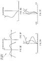
- FIGS. 3A-C are MTF performance plots (three) taken at room temperature, To, for an incident wavelength of 546 nm for the lens design without the adjacent zone spacing for athermalizing the lens, which is the case also for the plots of FIGS. D-I.
- Fractional object heights are: (1) FOB 0 (0° to the optical axis) - See FIG. 3A; (2) FOB 0.7 (22° to the lens axis) - See FIG. 3B; and (3) FOB 0.9 (31-degree field angle) - See FIG. 3C.
- the curves in each plot are marked with a vertical dash, a square and a triangle for idealized tangential and sagittal measurements, respectively.
- the exemplary meniscus-type DOE diffractive optical element
- the exemplary meniscus-type DOE is designed to have an MTF of about 50% modulation at 60-cycles on-axis (scale is in cycles/mm). All field angles, FOB's, shows that the lens performs well as optimized at room temperature To.
- the top curve (marked with triangles) in all three plots (FIGS. 3A-C) shows the theoretical limit for a diffraction-limited, perfectly designed lens.
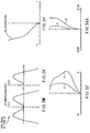
- FIG. 3D shows point spread function (PSF) plots, which show the energy distribution, on-axis at the central focal spot.
- the focused beam is well within the design criteria of 30 microns at 50% of maximum intensity (scale in mm).
- FIGS. 3E and F are opd fans which show difference in ray paths at the focal plane as a function of light rays transmitted across the lens diameter. There is a small departure from the desired, perfect spherical wavefront, showing astigmatism and coma aberrations, but minimized for a single-element lens (scale in wavelengths).
- FIG. 3G is a plot of distortion at the film plane. Acceptable distortion should be no greater than 4% magnification -- and is below 1%, in this lens exemplary DOE design (scale in percent).
- FIG. 3H shows field sags, namely sagittal and tangential astigmatism that cannot be fully corrected in a simple lens, but is somewhat improved by the exemplary DOE and by using a curved film plane (in the long dimension, scale in wavelengths).
- FIG. 3I plots lateral color. This plot shows that correction for chromatic aberration is provided across a spectrum of 440nm to 650nm.
- the lens design optimization includes minimum color separation in the film plane for primary color (blue to red) and secondary (blue to green) wavelengths, scale in mm.
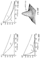
- FIGS. 3J-R are plots similar to FIG. 3 A-I for the non-athermalized lens at room temperature. There is some degradation of the performance shown in FIGS. 3A-I, in a non-acceptable amount, including point spread function (PSF), 3M.
- PSF point spread function
- FIGS. 3S-AA are plots similar to FIGS. 3A-I, respectively, taken when the lens is cold (-15°C).
- FIGS. 3AB-AJ are plots similar to FIGS. 3A-I, respectively, taken when the lens is hot (+15°C).
- the performance of the athermalized lens at low temperature e.g., minus 15° below temperature
- at room temperature e.g., 15° above room temperature
- MTF modulation transfer function
- PSF point spread function
- Other important imaging aberrations are retained within acceptable levels for a single-element lens imaging onto a focal plane, like a film plane.
- the kinoform-type lens remains corrected for lateral color, as reflected in plots of primary and secondary aberration taken over a wavelength range extending from 440 nm to 650 nm.
- Back focal length of the lens is maintained over a range compensating for thermal effects, as reflected in plots of optical path difference (OPD); while astigmatism, field sags, stays within imaging tolerance for a single element lens possessing no other lens elements.
- OPD optical path difference
- the temperature-induced optical response so sited thus illustrates the successful operation of an lens athermalized in accordance with the invention, as an imaging lens.
Landscapes
- Physics & Mathematics (AREA)
- General Physics & Mathematics (AREA)
- Optics & Photonics (AREA)
- Lenses (AREA)
- Diffracting Gratings Or Hologram Optical Elements (AREA)
Applications Claiming Priority (4)
| Application Number | Priority Date | Filing Date | Title |
|---|---|---|---|
| US520395P | 1995-08-16 | 1995-08-16 | |
| US5203 | 1995-08-16 | ||
| US668166 | 1996-06-21 | ||
| US08/668,166 US5745289A (en) | 1996-06-21 | 1996-06-21 | Athermalized diffractive optical elements |
Publications (2)
| Publication Number | Publication Date |
|---|---|
| EP0758753A2 true EP0758753A2 (de) | 1997-02-19 |
| EP0758753A3 EP0758753A3 (de) | 1997-08-06 |
Family
ID=26674062
Family Applications (1)
| Application Number | Title | Priority Date | Filing Date |
|---|---|---|---|
| EP96112472A Withdrawn EP0758753A3 (de) | 1995-08-16 | 1996-08-02 | Diffraktive optische Elemente |
Country Status (2)
| Country | Link |
|---|---|
| EP (1) | EP0758753A3 (de) |
| JP (1) | JPH09105802A (de) |
Cited By (7)
| Publication number | Priority date | Publication date | Assignee | Title |
|---|---|---|---|---|
| EP0840144A1 (de) * | 1996-10-29 | 1998-05-06 | Canon Kabushiki Kaisha | Linsensystem mit einer diffractiven und einer refractiven Oberfläche und eine dieses Linsensystem verwendende Vorrichtung |
| US6181485B1 (en) | 1999-06-23 | 2001-01-30 | Read-Rite Corporation | High numerical aperture optical focusing device for use in data storage systems |
| US6185051B1 (en) | 1999-06-23 | 2001-02-06 | Read-Rite Corporation | High numerical aperture optical focusing device for use in data storage systems |
| DE102005022636A1 (de) * | 2005-05-11 | 2006-11-23 | Everspring Industry Co. Ltd., Kweishan | Dünne sphärische Linse |
| DE19924640B4 (de) * | 1998-05-29 | 2009-04-16 | Hoya Corp. | Optisches Abtastgerät für eine optische Platte |
| CN103782511A (zh) * | 2011-06-10 | 2014-05-07 | 奥丽福美洲公司 | 用于优化透镜材料和透镜阵列的方法及其装置 |
| CN112188063A (zh) * | 2020-09-30 | 2021-01-05 | 维沃移动通信有限公司 | 摄像装置及电子设备 |
Citations (1)
| Publication number | Priority date | Publication date | Assignee | Title |
|---|---|---|---|---|
| US5260820A (en) | 1991-05-14 | 1993-11-09 | Bull James G | Airborne fiber optic decoy architecture |
Family Cites Families (2)
| Publication number | Priority date | Publication date | Assignee | Title |
|---|---|---|---|---|
| JPH01206682A (ja) * | 1988-02-15 | 1989-08-18 | Omron Tateisi Electron Co | 半導体レーザ光源 |
| US5260828A (en) * | 1992-03-27 | 1993-11-09 | Polaroid Corporation | Methods and means for reducing temperature-induced variations in lenses and lens devices |
-
1996
- 1996-08-02 EP EP96112472A patent/EP0758753A3/de not_active Withdrawn
- 1996-08-14 JP JP24679096A patent/JPH09105802A/ja not_active Withdrawn
Patent Citations (1)
| Publication number | Priority date | Publication date | Assignee | Title |
|---|---|---|---|---|
| US5260820A (en) | 1991-05-14 | 1993-11-09 | Bull James G | Airborne fiber optic decoy architecture |
Cited By (11)
| Publication number | Priority date | Publication date | Assignee | Title |
|---|---|---|---|---|
| EP0840144A1 (de) * | 1996-10-29 | 1998-05-06 | Canon Kabushiki Kaisha | Linsensystem mit einer diffractiven und einer refractiven Oberfläche und eine dieses Linsensystem verwendende Vorrichtung |
| US6590708B2 (en) | 1996-10-29 | 2003-07-08 | Canon Kabushiki Kaisha | Lens system having diffracting surface and refracting surface and optical apparatus using the lens system |
| DE19924640B4 (de) * | 1998-05-29 | 2009-04-16 | Hoya Corp. | Optisches Abtastgerät für eine optische Platte |
| US6181485B1 (en) | 1999-06-23 | 2001-01-30 | Read-Rite Corporation | High numerical aperture optical focusing device for use in data storage systems |
| US6185051B1 (en) | 1999-06-23 | 2001-02-06 | Read-Rite Corporation | High numerical aperture optical focusing device for use in data storage systems |
| DE102005022636A1 (de) * | 2005-05-11 | 2006-11-23 | Everspring Industry Co. Ltd., Kweishan | Dünne sphärische Linse |
| DE102005022636B4 (de) * | 2005-05-11 | 2014-03-20 | Everspring Industry Co. Ltd. | Dünne sphärische Linse und Verwendung einer Solchen |
| DE102005022636B8 (de) | 2005-05-11 | 2014-06-18 | Everspring Industry Co., Ltd. | Dünne sphärische Linse und Verwendung einer Solchen |
| CN103782511A (zh) * | 2011-06-10 | 2014-05-07 | 奥丽福美洲公司 | 用于优化透镜材料和透镜阵列的方法及其装置 |
| CN112188063A (zh) * | 2020-09-30 | 2021-01-05 | 维沃移动通信有限公司 | 摄像装置及电子设备 |
| CN112188063B (zh) * | 2020-09-30 | 2022-09-02 | 维沃移动通信有限公司 | 摄像装置及电子设备 |
Also Published As
| Publication number | Publication date |
|---|---|
| JPH09105802A (ja) | 1997-04-22 |
| EP0758753A3 (de) | 1997-08-06 |
Similar Documents
| Publication | Publication Date | Title |
|---|---|---|
| US5745289A (en) | Athermalized diffractive optical elements | |
| US5541774A (en) | Segmented axial gradient lens | |
| US5696371A (en) | Diffractive/refractive lenslet array | |
| US5420720A (en) | Internally cooled large aperture microlens array with monolithically integrated microscanner | |
| EP0549146B1 (de) | Zoomobjektiv mit refraktiven und diffraktiven optischen Elementen | |
| EP0532267B1 (de) | Optisches System zur wiederholten Abbildung mit refraktiven und diffraktiven optischen Elementen | |
| US5703722A (en) | Segmented axial gradinet array lens | |
| EP0517409B1 (de) | Optisches System aus refraktiven und diffraktiven optischen Elementen zur Korrektur chromatischer Aberrationen | |
| US6262844B1 (en) | Optical systems employing stepped diffractive surfaces | |
| US5751492A (en) | Diffractive/Refractive lenslet array incorporating a second aspheric surface | |
| US5880879A (en) | Objective lens system utilizing diffractive optical element | |
| EP0441206A1 (de) | Optisches Element mit asphärischen und binär beugenden optischen Oberflächen | |
| EP0840144A1 (de) | Linsensystem mit einer diffractiven und einer refractiven Oberfläche und eine dieses Linsensystem verwendende Vorrichtung | |
| US6515955B2 (en) | Objective optical system for optical pick-up | |
| US20230065152A1 (en) | Imaging lens | |
| EP0750205B1 (de) | Objektivlinsensystem | |
| EP0758753A2 (de) | Diffraktive optische Elemente | |
| CN100410714C (zh) | 成像光学系统 | |
| Ryu et al. | Achromatic and athermal design of a mobile-phone camera lens by redistributing optical first-order quantities | |
| EP0457493B1 (de) | Zoomlinse | |
| EP0193231B1 (de) | Projektionsobjektiv | |
| Bigwood | New infrared optical systems using diffractive optics | |
| CN117148547A (zh) | 一种光学系统及光学镜头 | |
| KR19980020576A (ko) | 프로젝션 렌즈계 | |
| KR100404727B1 (ko) | 회절 요소 및 비구면 요소를 한 면에 구비하는 렌즈 및이를 구비한 광학 장치 |
Legal Events
| Date | Code | Title | Description |
|---|---|---|---|
| PUAI | Public reference made under article 153(3) epc to a published international application that has entered the european phase |
Free format text: ORIGINAL CODE: 0009012 |
|
| AK | Designated contracting states |
Kind code of ref document: A2 Designated state(s): DE FR GB |
|
| PUAL | Search report despatched |
Free format text: ORIGINAL CODE: 0009013 |
|
| AK | Designated contracting states |
Kind code of ref document: A3 Designated state(s): DE FR GB |
|
| 17P | Request for examination filed |
Effective date: 19980114 |
|
| 17Q | First examination report despatched |
Effective date: 20010607 |
|
| STAA | Information on the status of an ep patent application or granted ep patent |
Free format text: STATUS: THE APPLICATION IS DEEMED TO BE WITHDRAWN |
|
| 18D | Application deemed to be withdrawn |
Effective date: 20011018 |