EP0758831A2 - Bildaufnahmevorrichtung mit verschiedenen Methoden zur Bildpunktverschiebung - Google Patents
Bildaufnahmevorrichtung mit verschiedenen Methoden zur Bildpunktverschiebung Download PDFInfo
- Publication number
- EP0758831A2 EP0758831A2 EP96112905A EP96112905A EP0758831A2 EP 0758831 A2 EP0758831 A2 EP 0758831A2 EP 96112905 A EP96112905 A EP 96112905A EP 96112905 A EP96112905 A EP 96112905A EP 0758831 A2 EP0758831 A2 EP 0758831A2
- Authority
- EP
- European Patent Office
- Prior art keywords
- image
- image sensing
- point array
- sensing
- sensing point
- Prior art date
- Legal status (The legal status is an assumption and is not a legal conclusion. Google has not performed a legal analysis and makes no representation as to the accuracy of the status listed.)
- Granted
Links
Images


Classifications
-
- H—ELECTRICITY
- H04—ELECTRIC COMMUNICATION TECHNIQUE
- H04N—PICTORIAL COMMUNICATION, e.g. TELEVISION
- H04N25/00—Circuitry of solid-state image sensors [SSIS]; Control thereof
- H04N25/48—Increasing resolution by shifting the sensor relative to the scene
-
- H—ELECTRICITY
- H04—ELECTRIC COMMUNICATION TECHNIQUE
- H04N—PICTORIAL COMMUNICATION, e.g. TELEVISION
- H04N23/00—Cameras or camera modules comprising electronic image sensors; Control thereof
- H04N23/80—Camera processing pipelines; Components thereof
- H04N23/84—Camera processing pipelines; Components thereof for processing colour signals
-
- H—ELECTRICITY
- H04—ELECTRIC COMMUNICATION TECHNIQUE
- H04N—PICTORIAL COMMUNICATION, e.g. TELEVISION
- H04N25/00—Circuitry of solid-state image sensors [SSIS]; Control thereof
- H04N25/10—Circuitry of solid-state image sensors [SSIS]; Control thereof for transforming different wavelengths into image signals
- H04N25/11—Arrangement of colour filter arrays [CFA]; Filter mosaics
- H04N25/13—Arrangement of colour filter arrays [CFA]; Filter mosaics characterised by the spectral characteristics of the filter elements
- H04N25/133—Arrangement of colour filter arrays [CFA]; Filter mosaics characterised by the spectral characteristics of the filter elements including elements passing panchromatic light, e.g. filters passing white light
-
- H—ELECTRICITY
- H04—ELECTRIC COMMUNICATION TECHNIQUE
- H04N—PICTORIAL COMMUNICATION, e.g. TELEVISION
- H04N25/00—Circuitry of solid-state image sensors [SSIS]; Control thereof
- H04N25/10—Circuitry of solid-state image sensors [SSIS]; Control thereof for transforming different wavelengths into image signals
- H04N25/11—Arrangement of colour filter arrays [CFA]; Filter mosaics
- H04N25/13—Arrangement of colour filter arrays [CFA]; Filter mosaics characterised by the spectral characteristics of the filter elements
- H04N25/134—Arrangement of colour filter arrays [CFA]; Filter mosaics characterised by the spectral characteristics of the filter elements based on three different wavelength filter elements
Definitions
- the present invention relates to an image sensing apparatus and method using a solid-state image sensing device, such as CCD, and more particularly, to an image sensing apparatus and method realizing high-resolution image sensing by using "pixel shifting technique" and a method of dealing with obtained data of the plurality of images sensed by using the pixel shifting technique.
- a solid-state image sensing device such as CCD
- method (c) namely pixel shifting technique
- the pixel shifting technique is that a plurality of images of an object are sensed as shifting image formation positions on the image sensing device, and combined to produce a single high-resolution still image. This technique is disclosed in the Japanese Patent Publication No. 50-17134, for example.
- the image sensing apparatus using a solid-state image sensing device focuses on the object, measures light exposure, and adjusts white balance for each sensed image.
- focusing on the object, measurement of light exposure, and correction of white balance have not been exclusively considered for the pixel shifting technique in which a plurality of images are sensed by shifting the relative positions between the image sensing device and the object in the horizontal direction, vertical direction and oblique direction, and combined into a single image of high quality.
- the present invention has been made in consideration of the above situation, and has as its object to provide an image sensing apparatus and method having a plurality of image sensing modes for shifting a solid-state image sensing device to different positions so as to be able to obtain images of different resolutions, as well as to provide a data handling method of image data obtained by the aforesaid image sensing apparatus.
- an image sensing apparatus which obtains an image of high resolution by using pixel shifting technique, comprising: image sensing means for sensing an image of an object to obtain image data; shifting means for shifting image formation position of the image of the object on the image sensing means; selection means for selecting one of a plurality of image sensing modes each of which performs image sensing operation using different pixel shifting method; and combining means for combining a plurality of sensed images.
- an image sensing apparatus which obtains an image of high resolution by using pixel shifting technique, comprising: focus control means for controlling focus of image sensing means; exposure control means for controlling exposure of the image sensing means; white balance control means for controlling white balance of image data obtained by the image sensing means; and storage means for storing conditions controlled by the focus control means, the exposure control means and the white balance control means during a first image sensing operation, wherein second and later image sensing operation are performed under the conditions stored in the storage means.
- an image sensing apparatus which obtains an image of high resolution by using pixel shifting technique, comprising: image sensing means for sensing an image of an object to obtain image data; shifting means for shifting image formation positions of the image of the object on the image sensing means by a predetermined amount; read control means for controlling timing of reading image data from the image sensing means so as to compensate the shifted predetermined amount; and combining means for combining a plurality of sensed images.
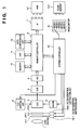
- Fig. 1 is a block diagram illustrating a configuration of an image sensing apparatus, a digital still camera, according to a first embodiment of the present invention. The configuration and operation of the digital still camera are explained below with reference to Fig. 1.
- the system controller 15 determines speed for writing and reading to/from the connected storage medium 8-1 or 8-2.
- a compression ratio for compressing image data is determined in accordance with the determined speed. This operation will be explained later in detail.
- an image sensing mode is manually selected by using a mode switch 16.
- modes provided in the first embodiment, and they are:
- An image of an object passes through a lens system 1 and an optical low pass filter (LPF) set 1 or 2 (referred by 2-1 and 2-2 in Fig. 1), then forms as an image on a CCD 3.
- LPF optical low pass filter
- Each of the optical LPF sets 1 and 2 is composed of a single or a plurality of quartz plates, and inserted in or extracted out of the light path of the image of the object by a filter insertion/extraction unit 13-1 or 13-2 under control of the system controller 15 in accordance with the mode selected.
- the optical image formed on the CCD 3 is outputted as electric signals, then reset noises included in the electric signals of the image are reduced by a correlated double sampling (CDS) circuit 4, then the image signals are digitized by an analog-digital (A/D) converter 5. Further, the digital image signals are temporarily stored in a memory 10 through a memory controller 6.
- CDS correlated double sampling
- the CCD 3 has a 1536 ⁇ 1024 pixel array (about 1,500,000 pixels), which are covered with a color filter of complementary colors arranged in stripe. Further, the A/D converter 5 has linear and 10-bit characteristics.
- Image data (unprocessed data read from the single CCD) of 10-bit depth stored in the memory 10 enters a data compression unit 12 (based on JPEG) via a digital signal processor (DSP) 11.
- DSP digital signal processor
- the compression ratio is set in advance in the data compression unit 12, dependent upon the connected storage medium 8-1 or 8-2.
- the data entered the data compression unit 12 is compressed with the compression ratio, and stored in the storage medium 8-1 or 8-2.
- the second image of the object among the plurality of images to be sensed, is sensed.
- the optical LPF set 1 or 2 is inserted/extracted in accordance with the selected image sensing mode.
- a CCD shifting unit e.g., piezoelectric element 9
- the relative position of the CCD 3 is moved in the horizontal direction or the vertical direction, then the second image is sensed.
- the flow of data of the second image is same as that of the data of the first image.
- the aforesaid processes are repeated a predetermined number of times, and compressed data of a plurality of images sensed as shifting the CCD 3 are stored in the storage medium 8-1 or 8-2.
- a process of combining the data of the plurality of images starts. Necessary portions of data is read out from the storage medium 8-1 or 8-2 and decompressed by the data compression unit 12, then converted into 10-bit linear data by the DSP 11. Thereafter, the order of the image data are rearranged in accordance with the positions of the CCD 3 in pixel shifting. Further, the image data is applied with various signal processes, such as color conversion, aperture correction and base clipping, then compressed again by the data compression unit 12 if necessary, and written to the storage medium 8-1 or 8-2. The compression ratio at this time may be
- the process of combining the stored data is performed by reading image data from the storage medium 8-1 or 8-2 by block, in other words, by reading the image data for corresponding area of each image data.
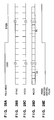
- Figs. 3A to 3F are explanatory views showing image sensing point arrays in the mode 1.
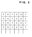
- color filter chips of C (cyan), G (green) and Y (yellow) are arranged in vertical stripe, as shown in Fig. 2, and provided on the CCD 3 having 1536 ⁇ 1024 pixels (about 1,500,000 pixels) as an on-chip filter.
- a pixel shifting pattern by using the above CCD 3 will be described with reference to Figs. 3A to 3F.
- Image sensing points to which color filter chips of each color (C, G and Y) contribute are shown by different kinds of circles for making it easier to understand.
- the first image is sensed (Fig. 3A).
- the image sensing point array where the first image is sensed are referred as “reference image sensing point array”, hereinafter.
- the CCD 3 is shifted by the distance corresponding to the interval between pixels ("pitch") in the horizontal direction, then the second image is sensed.
- image sensing points contributed by C in the first image are contributed by G (Fig. 3B).
- the CCD 3 is further shifted by a pitch in the horizontal direction, then the third image is sensed.
- the points contributed by G in the second image are contributed by Y (Fig. 3C).
- the fourth image is sensed in image sensing point array which is at a position shifted by a half pitch in the horizontal direction from the position of reference image sensing point array shown in Fig. 3A (Fig. 3D).
- the fifth image is sensed in image sensing point array which is at a position shifted by a pitch in the horizontal direction from the position of the image sensing point array for the fourth image, shown in Fig. 3D.
- the points contributed by C in the fourth image are contributed by G in the fifth image (Fig. 3E).
- the sixth image is sensed in image sensing point array which is at a position shifted by a pitch in the horizontal direction from the position of the image sensing point array for the fifth image shown in Fig. 3E (Fig. 3F).
- the image data of the six sensed images corresponds to data of images of three colors, C, G and Y, each sensed at image sensing points of a CCD having about 1,500,000 pixels and at their interpolation points in the horizontal direction.
- the seventh image is sensed in image sensing point array which is at a position shifted by a half pitch in the vertical direction from the position of the reference image sensing point array. Thereafter, the CCD 3 is further shifted in the horizontal direction from the position where the seventh image is sensed to obtain five more images, and the method of shift in the horizontal direction is same as that explained with reference to Figs. 3A to 3F.
- the image data of another six sensed images corresponds to data of images of three colors, C, G and Y, each sensed at image sensing points of a CCD having about 1,500,000 pixels shifted by a half pitch in the vertical direction with respect to the reference image sensing array and at their interpolation points in the horizontal direction.
- the image data of twelve sensed images corresponds to data of images of three colors, C, G and Y, each sensed in the reference image sensing point array of a CCD having about 1,500,000 pixels, their interpolation points in the horizontal direction, their interpolation points in the vertical direction and image sensing points shifted by a half pitch both in the horizontal and vertical directions from the reference image sensing point array.
- This is equivalent to data of images of three colors each sensed by about 6,000,000 pixels of a CCD.
- the data obtained by sensing twelve images is equivalent to data obtained with three CCDs, each of which has about 6,000,000 pixels, in a single image sensing process. Therefore, the mode 1 is also called as "three high resolution image sensor mode".
- the data of twelve images each obtained by reading the CCD 3 having 1536 ⁇ 1024 pixels is rearranged so as to form three images consisting of 3072 ⁇ 2018 pixels (Fig. 4A). Thereafter, the rearranged data is applied with a matrix operation, thereby transformed into R, G and B data.
- the matrix operation is as follow.
- FIGs. 5A and 5B are explanatory views showing image sensing point arrays in the mode 2.
- the optical LPF set 1 is inserted in the light path. Then, the first image is sensed in the image sensing point array shown in Fig. 5A (reference image sensing point array). Thereafter, the image sensing point array is shifted by 1.5 pitches in the horizontal direction and by a half pitch in the vertical direction, then the second image is sensed in the image sensing point array shown in Fig. 5B.
- the resulted image sensing points appear as an array shown in Fig. 6. Accordingly, the obtained data is equivalent to data obtained by using a single CCD having about 3,000,000 pixels in a single image sensing process. It should be noted that the combined image sensing points are not at intersections of cross stripes in the right direction, but at intersections of cross stripes tilted by 45 degrees according to the first embodiment.
- Figs. 7A and 7B are explanatory views for explaining generation of luminance signals in the mode 2.
- the data for the odd-number lines (Fig. 7A) which forms half of a final combined image and the data for the even-number lines (Fig. 7B) which forms the other half of the combined image can be obtained by alternatively reading data in two adjacent horizontal lines of image sensing point array, as shown in Fig. 6, in different combinations.
- image data equivalent to image data obtained by using a single image sensor having about 6,000,000 pixels in one image sensing operation can be obtained.
- the luminance signals of the even-number line data and of the odd-number line data obtained as described above are applied with base clipping, aperture correction and ⁇ correction, then outputted.
- the C, G and Y signals before being read by two adjacent lines are separately read out, converted into R, G and B signals by a matrix 1 unit (same as in the mode 1), passes through LPFs and ⁇ correction circuits, then enter a matrix 2 unit (shown in Fig. 8).
- the R, G and B signals are converted to color difference signals, R-Y, B-Y and B-Y. Thereafter, the generated color difference signals are added with luminance signals Y which are obtained as described above, thereby obtaining R, G and B signals.
- Fig. 9 is a graph showing color carrier and luminance carrier generation points in a frequency space in an image sensed in the image sensing point array shown in Fig. 6 (mode 2).
- fs is the sampling frequency in the horizontal direction
- f's is the sampling frequency in the vertical direction.
- the optical LPF set 1 (2-1) for dealing with the carriers shown in Fig. 9 reduces the color carrier signals on oblique dashed lines labeled by traps 1 and 2 in Fig. 10 so as to make the response equal to 0, and reduces the luminance carrier signals on a vertical dashed line labeled by trap 3 in Fig. 10 so as to make the response be 0.
- the optical LPF set 1 having the aforesaid characteristics can be made of three quartz plates.
- FIGS. 11A to 11C are explanatory views showing image sensing point arrays in the mode 3.
- the obtained image data is rearranged to form three images of C, G and Y (Fig. 12).
- the processes applied to the rearranged signals are mostly the same as in the mode 1 explained with reference to Fig. 4B.
- FIGs. 13A and 13B are explanatory views showing image sensing point arrays in the mode 4.
- the optical LPF set 2 is inserted in the light path. Thereafter the first image is sensed (Fig. 13A). Next, the CCD 3 is shifted by 1.5 pitch in the horizontal direction and the second image is sensed (Fig. 13B).
- Fig. 14 shows a combined image sensing point array when the two images obtained as above are combined.
- the density of the image sensing points in the horizontal direction in mode 4 is double the density of the image sensing points of the CCD 3, and color carrier shifts to higher frequency.
- Figs. 15A and 15B are explanatory views showing signal processing in the mode 4.
- the image data of the two sensed images are combined together to be data of an image composed of 3072 ⁇ 1024 pixels (Fig. 15A).
- the combined data is applied with signal processes and inputted into an anisotropic magnification circuit so as to generate R, G and B signals (Fig. 15B).
- the anisotropic magnification circuit can be a simple digital LPF or an adder for adding two adjacent pixels in horizontal lines.
- Fig. 16 is a graph showing points where color and luminance carrier signals are generated and trap of the optical filter set 2. when the optical LPF set 2 is used, carrier signals are trapped in a frequency which is much lower than an actual frequency (i.e., Nyquist frequency of color signals), thereby greatly reducing color moiré.
- Mode 5 will be explained. This mode is called the "single normal resolution image sensor mode 2.
- Fig. 18 is a graph showing points where color and luminance carrier signals are generated and trap of the optical filter set 2.
- An optical LPF which traps signals at the trap frequency shown in Fig. 18 can be realized with a quartz plate.
- a storage medium e.g., flash memory
- the speed is determined in the initial self-check process, and the compression ratio applied to image data to be stored in the storage medium is changed (more specifically, when the speed is slow, then the image data is more compressed), thereby compensating the total time of image sensing operations for obtaining a final combined image.
- unprocessed image data from the CCD 3 of 10-bit depth is converted into 8-bit signals by using a table stored in the DSP 11 with ⁇ of 0.45. It is possible to perform white balance process before transforming the image data of 10-bit depth.
- aliasing noises are especially reduced when sensing a non-chromatic object, and the deterioration of image becomes not very noticeable when data compression in the JPEG standard method is performed.
- the white balance process as described above is to be performed by the DSP 11 during compressing image data.
- the optical LPF set 1 is prepared exclusively for the mode 2, and a combined image of high resolution is obtained from two sensed images in the mode 2. However, it costs considerably to prepare the optical LPF set 1 which is used only in the mode 2.
- the optical LPF set 1 In order to omit the optical LPF set 1, it is possible to sense an image of high precision with two images sensed without a LPF set for obtaining luminance signals and an image sensed with the optical LPF set 2 for obtaining color signals.
- the two images for obtaining luminance signals are sensed in the same manner as in the mode 2 but without the optical LPF set 1. Then, only the luminance signals are generated from these two images.
- an image is sensed in the same manner as in the mode 5. Only the color signals are used out of the data of the image, and added with the luminance signals obtained from the two images. It should be noted that the color signals in this case have to be interpolated and expanded.
- the number of images to be sensed increases by one compared to that of mode 2, however, it is possible to reduce the manufacturing cost.
- the use of the LPF sets in the first embodiment is an example, and any configuration may be possible as far as it can trap the color carriers and the luminance carriers.
- the material of the optical LPF sets it is not limited to quartz plates, but can be other optical materials.
- edges of an image can expressed in high resolution by sensing the image by using pixel shifting technique.
- data corresponding to those edges which are not expressed in high resolution is generated by interpolating the first sensed image to compensate missing data, thereby avoiding the combined image from being unnatural.
- the CCD is moved by using a piezoelectric element or the like in the first embodiment, however, it is also possible to shift the light path of images by using an optical material, such as a wedge-shaped glass plate.
- the color filter is composed of color filter chips of complementary colors in the first embodiment, however, it is also possible to compose it with color filter chips of primary colors.
- an image sensing mode can be manually selected in accordance with characteristics of an object to be sensed, it is possible to obtain a combined image of high resolution effectively with the smaller number of images as well as to realize high speed image sensing operation depending upon the speed of writing and reading to/from a storage medium.
- Fig. 19 is a block diagram illustrating a configuration of an image sensing apparatus according to the second embodiment of the present invention.
- reference numerals 21 and 22 denote object lenses, and specifically, reference numeral 21 denotes a focusing lens system and reference numeral 22 denotes other object lenses; 23, an iris diaphragm; 24, an optical LPF; 25, a solid-state image sensing device, such as a CCD; 26, a pixel shifting unit; 27, an A/D converter; 28, a memory controller; 29, a digital signal processor (DSP); 210, a memory; 211, a focus detector; 212, exposure detector; 213, a white balance (WB) detector; 214, a system controller; 215, a focus controller; 216, a focusing lens driver; 217, a lens position detector; 218, an iris diaphragm controller; 219, an iris diaphragm driver; 220, a CCD driver; 221, a D/A converter; and 222, a hard disk.
- DSP digital signal processor
- exposure control includes control of incoming external light, such as control of iris diaphragm, shutter speed, and stroboscopic operation.
- the quantity of light of luminous flux which passed through the focusing lens system 21 for controlling focus is controlled by the iris diaphragm 23, further passes through the lens 22 and the optical LPF 24 which is made of quartz, then forms an image on the solid-state image sensing device 25.
- the optical LPF 24 has spatial frequency characteristics to make the response be 0 at Nyquist frequency of a combined image which is finally obtained by using pixel shifting technique (i.e., 1/2 of the Nyquist frequency of the solid-state image sensing device 25) . It acts so as to reduce aliasing noises.
- the solid-state image sensing device 25 shifts on a plane which is perpendicular to the optical axis by the pixel shifting unit 26.
- a color filter array composed of color filter chips of complementary colors, Cy, Ye, Mg and G, are provided as shown in Figs. 20A to 20D.
- the pixel shifting unit 26 can shift the solid-state image sensing device 25 in the horizontal and vertical directions as indicated by arrows in Fig. 20A by using a piezoelectric element. After sensing an image 1 at the position shown in Fig. 20B, the pixel shifting unit 26 shifts the solid-state image sensing device 25 in the horizontal direction by p/2 and an image 2 is sensed at the position shown in Fig. 20C. The pixel shifting unit 26 further shifts in the vertical direction by p/2 and an image 3 is sensed at the position shown in Fig.
- Image signals obtained from the solid-state image sensing device 25 are converted into digital signals by the A/D converter 27, passes through the memory controller 28, then transmitted to the DSP 29.
- the DSP 29 generates luminance signals of an area which is assigned for focusing, then the generated luminance data is transmitted to the focus detector 211.
- the focus detector 211 is composed of a band-pass filter (BPF) 211a and an integrator 211b as shown in Fig. 22.
- the BPF 211a passes the middle to high frequency components of the inputted luminance signals, and the integrator 211b integrates the values of these signals.
- the middle to high frequency components corresponds to contrast of the sensed object, thus the difference in contrast, namely the integrated value of the middle to high frequency component values, can be considered as a focus evaluation value.
- This value has characteristics expressed by a concave-down shaped graph as shown in Fig. 23, in which the maximum value corresponds to the focusing state, and as the value decreases, it shows that an image is more defocused.
- the focus evaluation value obtained by the focus detector is transmitted to the system controller 214, and the system controller 214 controls the focusing lens driver 216, through the focus controller 215, to drive the focusing lens system 21 so as to move in the direction in which the focus evaluation value increases.
- the lens position detector 217 is for detecting the position of the focusing lens system 21, and the output from the lens position detector 217 is fed back to the focus controller 215. The aforesaid operation is repeated, and when the focus evaluation value outputted from the focus detector 211 reaches the maximum, then the focusing operation is completed.
- the exposure detector 212 detects the current light exposure on the basis of the luminance signals obtained from the area which is set in advance for exposure measurement, then sends the detected information on exposure to the system controller 214. Then, electrical shutter speed and exposure value of the iris diaphragm are set so that the proper exposure can be achieved. Then the CCD driver 220 drives the solid-state image sensing device 25 at desired shutter speed, and the iris diaphragm controller 218 and the iris diaphragm driver 219 controls the opening of the iris diaphragm 23 to adjust the quantity of incoming light.
- the WB detector 213 detects a white point in the image on the basis of the color signals obtained from the DSP 29, then coefficients, for taking white balance, which color signals are multiplied by are transmitted to the DSP 29 through the system controller 214. These coefficients are used as parameters upon combining sensed images.
- the image 1 is temporarily stored in the memory 210 with the coefficients to be used for the white balance correction.
- the pixel shifting unit 26 shifts the solid-state image sensing device 25 in the horizontal direction by p/2, then the image 2 is sensed.
- the focusing on the object, measurement of light exposure, and white balance control are not performed, and the image 2 is sensed under the same conditions as for sensing the image 1.
- the image 2 is stored in the memory 210.
- the solid-state image sensing device 25 is shifted by p/2 in the vertical direction as shown in Fig. 20C and senses an image, then the image 3 is stored in the memory 210.
- the solid-state image sensing device 25 is further shifted by p/2 in the horizontal direction and senses an image, then the image 4 is stored in the memory 210.
- the DSP 29 With the images 1, 2, 3 and 4, and the coefficients for white balance correction obtained while processing the image 1, the DSP 29 generates a combined image having twice higher resolution both in the horizontal and vertical directions than the resolution of the pixels of the solid-state image sensing device 25.
- This combined image is outputted in the form of analog video signals which are converted by the D/A converter 221, as well as stored in the hard disk (HD) 222 as digital data.
- the image sensing conditions based on the focusing on the object, measurement of light exposure, and white balance correction performed during sensing the first images are fixed, and the second and later images are sensed under the same image sensing conditions, thereby the plurality of images to be combined for generating a single combined image are sensed under the same image sensing conditions. Therefore, it makes it easier to combine the plurality of images. Furthermore, exhaustion of a battery becomes slow.
- the second embodiment in a case of sensing a plurality of images by changing the relative positions between an image sensing device and an object and generating a single combined image of high resolution from the plurality of images, it becomes unnecessary to focus on the object, measure light exposure and control white balance each time when sensing the second or later images by fixing the image sensing conditions based on the focusing on the object and measurement of light exposure, and white balance control performed during sensing the first image and applying the fixed conditions to sense the second or later images. Accordingly, in a case where the image sensing conditions do not change much, such as a case of sensing a still life, the plurality of sensed images include less unevenness. Further, it becomes unnecessary to repeatedly focus on the object and measure light exposure and control white balance after they are measured once, thereby the time for image sensing operation is shortened as well as exhaustion of a battery becomes slower.
- the solid-state image sensing device 25 is shifted in the vertical and horizontal directions by p/2 to sense four images to generate a single combined image of high resolution.
- the pixel shifting pattern and the number of the images to be sensed are not limited as above, and any pixel shifting patterns can be applied as far as a plurality of images are sensed and these sensed images can be combined into a single image.
- the pixel shifting patterns explained in the mode 1 to the mode 4 in the first embodiment can be applied to the second embodiment.
- a variable apical angle prism is used for shifting image formation position.
- Fig. 24 is a block diagram illustrating a configuration of the image sensing apparatus of single image sensor type according to the third embodiment of the present invention.
- a traveling path of an image of an object which enters through a lens 31 is shifted by a variable apical angle prism 32. Thereafter, the image passes through a color filter 33a, the image of the object is formed on the surface of a CCD 33 which is as an image sensing device.
- variable apical angle prism 32 is composed in such a manner that two transparent plates 3102a and 3102b are shielded with expandable and contractile members 3101a and 3103b, and the area inside of the shielded plates is filled with liquid 3120 of a high refractive index. By tilting the transparent plates 3102a and 3102b with respect to the optical axis, it is possible to shift the image formation position on the CCD 33.
- the variable apical angle prism 32 will be described later in detail with reference to Fig. 30.
- the CCD 33 converts the formed image of the object into electrical signals, then the obtained electrical image signals are applied with sample and hold process, thereafter, converted into digital image signals by a sample and hold (S/H) and analog-digital (A/D) converter 34.
- a memory controller 35 takes the digital image signals and writes them in a memory 36, thereafter, reads out the digital image signals from the memory 36 and sends them to a digital signal processor (DSP) 37.
- DSP digital signal processor
- the signals processed by the DSP 37 are transmitted to a D/A converter 38 via the memory controller 35 and converted into analog signals, and outputted as video signals of a predetermined form. Further, the signals processed by the DSP 37 or the video signals can be stored by a recording device 320.
- the aforesaid operation can be performed under control of a system controller 39. Further, the system controller 39 controls pixel shifting by the variable apical angle prism 32 via a prism controller 310 as well as controls to drive the CCD 33 via a CCD driver 311.
- Fig. 25 is an explanatory view showing an arrangement of color filter chips, composing a color filter 33a, provided on the surface of the CCD 33.
- G filter chips are arranged at every other pixels in every line in such a manner that no two consecutive pixels both in the horizontal and vertical directions are provided with G filter chips, and the remaining pixels are provided with either R or B filters.
- This arrangement shown in Fig. 25 is called Bayer arrangement.
- luminance signal of each line can be obtained as following examples.
- Y2 B 12 , G 12 , B 22 , B 22 ...
- Y3 G 13 , R 13 , G 23 , R 23 ...
- R L R 11 , (R 11 +R 21 )/2, R 21 , (R 21 +R 31 )/2...
- G L1 G 11 , (G 11 +G 21 )/2, G 21 , (G 21 +G 31 )/2...
- B L1 B 11 , (B 11 +B 21 )/2, B 21 , (B 21 +B 31 )/2...
- color difference signals, R-Y, B-Y are generated by using these low frequency color signals, R L , G L and B L .
- Fig. 26 is a block diagram illustrating a configuration of a unit for a moving image processing in the DSP 37.
- a frame data stored in the memory 36 passes through a LPF 312, then through a band-pass filter 313, thereby aperture correction signals APC are obtained.
- the APC signals are added to signals from the LPF 312 by an adder 314, and luminance signals Y are obtained.
- the frame data is also applied with color separation by a color separation circuit 315 to obtain R, G and B signals.
- R, G and B signals pass through the LPFs 316, then the low frequency signals R L , G L and B L are obtained. Further, these signals R L , G L and B L are applied with a matrix operation by a matrix circuit 317, thereby the color difference signals R-Y and B-Y are generated.
- Fig. 27 shows a brief configuration of the CCD 33.
- electrical charge converted by each photodiode 33a is read out to a vertical register 33b, and transferred to two horizontal registers 33c and 33d by two lines in one horizontal blanking period in accordance with a vertical driving pulse VCCD.
- the transferred charge is outputted via output amplifiers 33e and 33f in one horizontal scanning period in accordance with horizontal driving pulses HCCD.
- first and second lines, third and fourth lines, and so on are added to generate image data of an ODD field
- second and third lines, fourth and fifth lines, and so on are added to generate image data of an EVEN field, and outputted as a field image consisting of 240 lines in one field period.
- Fig. 28A to Fig. 28E are timing charts showing timing of operation of the CCD 33 and the variable apical angle prism 32 when all the pixels are read out in one field period.
- Fig. 28A is a timing chart of a field index signal, and shows a period for reading out the ODD field and a period for reading out the EVEN field of a moving image.
- Fig. 28B is a timing chart of SYNC pulses and shows a horizontal synchronization signal.
- Fig. 28C is a timing chart of the vertical driving pulses VCCD, and
- Fig. 28D is a timing chart of the horizontal driving pulses HCCD.
- Fig. 28E shows a prism position control pulse for controlling the position of the variable apical angle prism 32. This pulse is for setting the variable apical angle prism 32 in the different positions when reading image signals for the ODD field and when reading image signals for the EVEN field, to shift pixels.
- Fig. 29B is an enlarged view of a part (a) of the timing chart, shown in the Fig. 28D, of the horizontal driving pulse HCCD when reading image signals for the ODD field
- Fig. 29C is an enlarged view of a part (b) of the timing chart, shown in Fig. 28D, when reading image signals for the EVEN field.
- the both Figs. 29B and 29C are shown in relationship with a horizontal blanking (BLK) period.
- the shifting amount namely one pixel distance, corresponds to the shifted amount of the image of the object.
- Fig. 30 is a decomposed perspective view of the variable apical angle prism 32.
- reference numeral 3102a and 3102b are the two transparent plates facing to each other, shielded with a film 3103 which is used as the expandable and contractile members 3101a and 3103b. Then, the room shielded by the plates 3102a and 3102b and the film 3103 is filled with liquid 3120 (refer to Fig. 24) of a high refractive index.
- Reference numerals 3104a and 3104b denote holding members for holding the transparent plates 3102a and 3102b and are supported by a rotational axis 3105a (called “pitch axis”, hereinafter) for tilting in the back and forth directions with respect to the optical axis and by a rotational axis 3105b (called “yaw axis”, hereinafter) for rotating in the right and left directions with respect to the optical axis, respectively.
- pitch axis tilting in the back and forth directions with respect to the optical axis
- yaw axis rotational axis
- Reference numeral 3106a denotes a driving coil fixed at an end of the holding member 3104a, and an permanent magnets 3107a and yokes 3108a and 3109a are provided so as to put the driving coil 3106a in between, and making a closed magnet circuit.
- Reference numeral 3111a denotes an arm which is integrally configured with the holding member 3104a and has a hole 3110a.
- Reference numeral 3112a is a light emit element, such as IRED and reference numeral 3113a is a light receiving element, such as a PSD, which outputs different signal depending upon the receiving position of luminous flux. These two elements 3112a and 3113a are arranged facing each other through the hole 3110a. Thus, luminous flux emitted from the light emit element 3112a passes through the hole 3110a and incidents on the light receiving element 3113a.
- Reference numeral 3114a and 3114b are vibration detectors attached to an holding member of the variable apical angle prism so as to detect the amounts of vibration in the back-and-forth rotational direction (pitch direction) and the right-and-left rotational direction (yaw direction) of the prism, respectively.
- Reference numeral 310a denotes a controller for controlling rotation of the transparent plate 3104a
- reference numeral 310b is a coil driver for driving the driving coil 3106a in accordance with driving signals from the controller 310a.
- reference numeral 3115 denotes a point of action of the driving coil 3106a in a space.
- a driving coil 3106b (not shown), a permanent magnet 3107b (not shown), yokes 3108b and 3109b (not shown), a hole 3110b, an arm 3111b, a light emit element 3112b (not shown), and a light receiving element 3113b (not shown) are also provided for the holding member 3104b which is supported by the yaw axis.
- These elements correspond to those referred by 3106a, 3107a, 3108a, 3109a, 3110a, 3111a, 3112a, 3113a, respectively, and operate in the likewise manner, thus the explanations of these elements are omitted.
- the controller 310a and the coil driver 310b control and drive the driving coils 3106a and 3106b (not shown), and tilt the transparent plate 3102a and rotate the transparent plate 3102b. Thereby, it is possible to shift the light path of the image of the object by one pixel in the horizontal direction and/or the vertical direction by each field.
- Fig. 31A shows a relative arrangement of the color filter by pixel on the surface of the CCD 33 when sensing the ODD field image.
- Fig. 31B shows a relative arrangement of the color filter by pixel on the surface of the CCD 33 when sensing the EVEN field image.
- the latter arrangement is shifted by one pixel in the horizontal direction with respect to the arrangement shown in Fig. 31A for sensing the ODD field image.
- Figs. 31A and 31B it looks as if the CCD 33 itself is shifted, however, the CCD 33 does not move in the third embodiment and it is the image formation position that shifted to the left in practice.
- the first image data as shown in Fig. 32A and the second image data as shown in Fig. 32B are obtained.
- G signals which contribute to generation of luminance signals mostly, are obtained throughout the pixels.
- R and B signals are arranged in horizontal stripes.
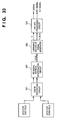
- FIG. 33 A block diagram of a still image processing unit for processing these first and second data is shown in Fig. 33.
- the data for ODD field and the data for the EVEN field as shown in Figs. 31A and 31B, respectively, are color-separated into the first image data and the second image data as shown in Fig. 32A and 32B by a color separation circuit 321.
- R and B signals they are interpolated in the vertical direction by an RB signal vertical interpolation circuit 322, thereafter low frequency color signals, R L , G L and B L are generated.
- the characteristics of pixel arrangement when sensing image data in high frequency range are that the R and B signals are arranged in horizontal stripes. Therefore, frequency components which is higher than the frequency of the R and B stripes have to be deleted, or moiré will occur.
- f SV is a sampling frequency in the vertical direction
- f SH is a sampling frequency in the horizontal direction.
- the image sensing apparatus is normally operated in a moving image mode. While sensing a moving image, the variable apical angle prism 32 and the timing to read image signals from the CCD are controlled as described above. Further, when a still image mode switch, which is not shown, is turned on, and the aforesaid combining processes are performed on field images which are sensed right after the switch is turned on, then the combined image of the two field images is outputted.
- a color filter of primary colors arranged in Bayer arrangement is used, and data sensed for the ODD field and data sensed for EVEN field are processed to increase the resolution.
- the present invention is not limited to this, and a color filter of complementary colors arranged in mosaic may be used to achieve the same advantages of the present invention.
- Fig. 35 shows an example of an arrangement of color filter chips of a color filter.
- the variable apical angle prism 32 is controlled so that an image formation position on the CCD is shifted by one pixel in the vertical and horizontal directions, namely four shifts make one cycle.
- the image formation position also shifts in the vertical direction, it is necessary to also change a timing to read the CCD in the vertical direction.
- the timing to read signals from the CCD 33 is controlled in the third embodiment, however, it is possible to compensate the shift when outputting a moving image.
- recording method of an output image is not explained in the third embodiment, but the image may be sequentially recorded as image data is outputted from the CCD, or may be recorded after signals from the CCD are converted to the luminance and color signals. Further, it is also possible to record an image of high resolution obtained by combining a plurality of sensed images.
- a variable apical angle prism is used for shifting the image formation position on a CCD, however, the present invention is not limited to this, and a piezoelectric element may be used for shifting the CCD to control the image formation position on the CCD.
- the third embodiment by shifting the image formation position on an image sensing device by a predetermined amount, e.g., a pixel, at a predetermined time interval, such as one field, by using a variable apical angle prism, and reading out signals from the image sensing device at a timing so as to compensate the shifted amount, e.g., a pixel, it is possible to provide an image sensing apparatus capable of sensing a still image as well as sensing a still image and a moving image at the same time at low cost.
- a predetermined amount e.g., a pixel
- An image sensing apparatus has a plurality of image sensing modes each of which performs image sensing operation using different pixel shifting method.
- One of these image sensing modes is selected through a selection unit in accordance with an object to be sensed, and a plurality of images of the object are sensed in image sensing position arrays on the basis of the selected image sensing mode.
- a combining unit combines the plurality of sensed images to obtain a single still image of high resolution.
Landscapes
- Engineering & Computer Science (AREA)
- Multimedia (AREA)
- Signal Processing (AREA)
- Physics & Mathematics (AREA)
- Spectroscopy & Molecular Physics (AREA)
- Color Television Image Signal Generators (AREA)
- Transforming Light Signals Into Electric Signals (AREA)
Applications Claiming Priority (9)
| Application Number | Priority Date | Filing Date | Title |
|---|---|---|---|
| JP20588895A JP4377970B2 (ja) | 1995-08-11 | 1995-08-11 | 撮像装置 |
| JP205888/95 | 1995-08-11 | ||
| JP20588895 | 1995-08-11 | ||
| JP20813795 | 1995-08-15 | ||
| JP7208137A JPH0955892A (ja) | 1995-08-15 | 1995-08-15 | 固体撮像装置 |
| JP208137/95 | 1995-08-15 | ||
| JP133496 | 1996-01-09 | ||
| JP8001334A JPH09191429A (ja) | 1996-01-09 | 1996-01-09 | 撮像装置 |
| JP1334/96 | 1996-01-09 |
Publications (3)
| Publication Number | Publication Date |
|---|---|
| EP0758831A2 true EP0758831A2 (de) | 1997-02-19 |
| EP0758831A3 EP0758831A3 (de) | 1999-09-15 |
| EP0758831B1 EP0758831B1 (de) | 2006-07-05 |
Family
ID=27274885
Family Applications (1)
| Application Number | Title | Priority Date | Filing Date |
|---|---|---|---|
| EP96112905A Expired - Lifetime EP0758831B1 (de) | 1995-08-11 | 1996-08-09 | Bildaufnahmevorrichtung mit verschiedenen Methoden zur Bildpunktverschiebung |
Country Status (4)
| Country | Link |
|---|---|
| US (1) | US6195125B1 (de) |
| EP (1) | EP0758831B1 (de) |
| DE (1) | DE69636322T2 (de) |
| ES (1) | ES2268697T3 (de) |
Cited By (15)
| Publication number | Priority date | Publication date | Assignee | Title |
|---|---|---|---|---|
| EP0888001A2 (de) | 1997-06-27 | 1998-12-30 | Canon Kabushiki Kaisha | Bildaufnahmevorrichtung |
| FR2779897A1 (fr) * | 1998-04-09 | 1999-12-17 | Aeg Infrarot Module Gmbh | Procede pour corriger les valeurs de gris d'images d'une camera numerique a infrarouge |
| EP0932296A3 (de) * | 1998-01-23 | 2000-07-05 | Canon Kabushiki Kaisha | Bildlesegerät |
| EP1017240A3 (de) * | 1998-12-31 | 2001-05-23 | Samsung Electronics Co., Ltd. | Farbsignalerzeugung |
| EP1246473A1 (de) * | 2001-03-27 | 2002-10-02 | Koninklijke Philips Electronics N.V. | Bildaufnahmegerät versehen mit Konturkompensationsschaltung und in diesem Gerät durchgeführtes Verfahren |
| FR2833794A1 (fr) * | 2001-12-14 | 2003-06-20 | Thales Sa | Systeme de detection et detecteur matriciel |
| EP1207685A3 (de) * | 2000-11-21 | 2004-11-03 | Hitachi, Ltd. | Farbbildaufnahmegerät mit Bildpunktverschiebung |
| EP1432231A3 (de) * | 2002-12-20 | 2005-02-02 | Smiths Heimann Biometrics GmbH | Einrichtung und Verfahren zur störungsarmen Aufnahme von hochaufgelösten zweidimensionalen Bildern |
| EP1458180A3 (de) * | 2003-03-04 | 2007-08-15 | Victor Company of Japan, Ltd. | Abbildungsvorrichtung |
| WO2009101103A1 (en) * | 2008-02-11 | 2009-08-20 | Thales Holdings Uk Plc | An imaging apparatus |
| US8283338B2 (en) | 2007-11-30 | 2012-10-09 | Kao Corporation | GIP secretion inhibitor |
| US8338389B2 (en) | 2009-06-17 | 2012-12-25 | Kao Corporation | Agent for preventing or ameliorating obesity |
| DE102012202207A1 (de) * | 2012-02-14 | 2013-08-14 | Paul Metzger | Bildaufnahmevorrichtung, Kamera und Bildaufnahmeverfahren |
| CN104394717A (zh) * | 2012-07-02 | 2015-03-04 | 荷兰联合利华有限公司 | 包含酸果胶凝胶的浓缩食品组合物 |
| CN108353152A (zh) * | 2015-10-27 | 2018-07-31 | 三星电子株式会社 | 图像处理设备及其操作方法 |
Families Citing this family (44)
| Publication number | Priority date | Publication date | Assignee | Title |
|---|---|---|---|---|
| JP3806211B2 (ja) * | 1997-01-08 | 2006-08-09 | 株式会社リコー | 撮像信号処理方法及び撮像信号処理装置 |
| JPH114401A (ja) * | 1997-06-13 | 1999-01-06 | Olympus Optical Co Ltd | 電子的撮像装置 |
| JPH118797A (ja) * | 1997-06-18 | 1999-01-12 | Olympus Optical Co Ltd | 電子的撮像装置 |
| US6639625B1 (en) * | 1997-07-16 | 2003-10-28 | Minolta Co., Ltd. | Image sensing device |
| CA2246404A1 (en) * | 1997-08-28 | 1999-02-28 | Koichi Shimada | Image sensing apparatus utilizing pixel-shifting |
| JP3796535B2 (ja) * | 1997-10-21 | 2006-07-12 | 株式会社ソキア | 電子レベル |
| US6744471B1 (en) | 1997-12-05 | 2004-06-01 | Olympus Optical Co., Ltd | Electronic camera that synthesizes two images taken under different exposures |
| JP3004618B2 (ja) * | 1998-02-27 | 2000-01-31 | キヤノン株式会社 | 画像入力装置及び画像入力システム及び画像送受信システム及び画像入力方法及び記憶媒体 |
| US6642956B1 (en) * | 1998-05-29 | 2003-11-04 | Agilent Technologies, Inc. | Digital image processor for a digital camera |
| JP3828283B2 (ja) * | 1998-06-04 | 2006-10-04 | 株式会社アドバンテスト | フラットパネル表示器検査用画像取得方法、フラットパネル表示器検査用画像取得装置 |
| JP4101954B2 (ja) * | 1998-11-12 | 2008-06-18 | オリンパス株式会社 | 画像表示装置 |
| US6624761B2 (en) | 1998-12-11 | 2003-09-23 | Realtime Data, Llc | Content independent data compression method and system |
| JP2000232653A (ja) * | 1999-02-08 | 2000-08-22 | Fuji Photo Film Co Ltd | 撮影装置 |
| US6429953B1 (en) * | 1999-05-10 | 2002-08-06 | Sharp Laboratories Of America, Inc. | Super resolution scanning using color multiplexing of image capture devices |
| US6601104B1 (en) | 1999-03-11 | 2003-07-29 | Realtime Data Llc | System and methods for accelerated data storage and retrieval |
| US6604158B1 (en) * | 1999-03-11 | 2003-08-05 | Realtime Data, Llc | System and methods for accelerated data storage and retrieval |
| WO2000074384A1 (en) * | 1999-05-27 | 2000-12-07 | Cambridge Research & Instrumentation Inc. | Imaging system using color sensors and tunable filters |
| JP2001094883A (ja) * | 1999-09-17 | 2001-04-06 | Victor Co Of Japan Ltd | 固体撮像装置 |
| JP3866888B2 (ja) * | 1999-10-28 | 2007-01-10 | 株式会社リコー | 撮像装置 |
| JP2001188202A (ja) * | 1999-12-28 | 2001-07-10 | Victor Co Of Japan Ltd | 撮像装置 |
| JP3991543B2 (ja) | 2000-01-11 | 2007-10-17 | 株式会社日立製作所 | 撮像装置 |
| US20010047473A1 (en) | 2000-02-03 | 2001-11-29 | Realtime Data, Llc | Systems and methods for computer initialization |
| JP2001330797A (ja) * | 2000-03-17 | 2001-11-30 | Olympus Optical Co Ltd | 偏心光学系を用いたカラー画像表示方式及び撮像方式 |
| JP2002077945A (ja) * | 2000-06-07 | 2002-03-15 | Canon Inc | 録画装置、撮像装置、撮像システム、信号処理方法、記録制御方法及び記憶媒体 |
| JP3762618B2 (ja) * | 2000-06-19 | 2006-04-05 | ペンタックス株式会社 | 電子カメラ |
| US8692695B2 (en) * | 2000-10-03 | 2014-04-08 | Realtime Data, Llc | Methods for encoding and decoding data |
| US9143546B2 (en) | 2000-10-03 | 2015-09-22 | Realtime Data Llc | System and method for data feed acceleration and encryption |
| US20030007089A1 (en) * | 2001-01-12 | 2003-01-09 | Anteon Corporation | Opto-electronic video compression system |
| JP2002218328A (ja) * | 2001-01-19 | 2002-08-02 | Ricoh Co Ltd | 画像入力装置、画像入力方法、およびその方法を実行するためのプログラムを格納したことを特徴とするコンピュータが読み取り可能な記録媒体 |
| US7386046B2 (en) | 2001-02-13 | 2008-06-10 | Realtime Data Llc | Bandwidth sensitive data compression and decompression |
| AU2003226047A1 (en) * | 2002-04-10 | 2003-10-27 | Pan-X Imaging, Inc. | A digital imaging system |
| JP2004023310A (ja) * | 2002-06-14 | 2004-01-22 | Hitachi Ltd | 画像入力装置 |
| US7421118B2 (en) * | 2003-03-17 | 2008-09-02 | Sharp Laboratories Of America, Inc. | System and method for attenuating color-cast correction in image highlight areas |
| JP2005109630A (ja) * | 2003-09-29 | 2005-04-21 | Sony Corp | カメラ装置 |
| JP2005175853A (ja) * | 2003-12-10 | 2005-06-30 | Canon Inc | 撮像装置及び撮像システム |
| JP4007986B2 (ja) * | 2004-09-21 | 2007-11-14 | オリンパス株式会社 | 撮像装置 |
| WO2006116726A2 (en) * | 2005-04-28 | 2006-11-02 | Applera Corporation | Multi-color light detection with imaging detectors |
| US8072502B2 (en) * | 2005-12-12 | 2011-12-06 | Sony Ericsson Mobile Communications Ab | Multi-mega pixel resolution with small sensor |
| WO2009145201A1 (ja) * | 2008-05-27 | 2009-12-03 | 三洋電機株式会社 | 画像処理装置、画像処理方法及び撮像装置 |
| JP5129685B2 (ja) * | 2008-08-06 | 2013-01-30 | キヤノン株式会社 | 輝度信号生成装置及び輝度信号生成方法、並びに撮像装置 |
| US20110149126A1 (en) * | 2009-12-22 | 2011-06-23 | Olympus Corporation | Multiband image pickup method and device |
| JP6508626B2 (ja) * | 2015-06-16 | 2019-05-08 | オリンパス株式会社 | 撮像装置、処理プログラム、撮像方法 |
| CN111835960A (zh) * | 2019-04-18 | 2020-10-27 | 北京小米移动软件有限公司 | 图像生成方法及装置、电子设备、可读存储介质 |
| CN112616007B (zh) * | 2020-12-31 | 2022-06-17 | 维沃移动通信有限公司 | 电子设备及其摄像模组 |
Family Cites Families (11)
| Publication number | Priority date | Publication date | Assignee | Title |
|---|---|---|---|---|
| JPS5017134A (de) | 1973-06-12 | 1975-02-22 | ||
| US4618990A (en) * | 1984-11-15 | 1986-10-21 | General Electric Company | Edge enhancement filtering for digital fluorography images |
| US4882619A (en) * | 1986-04-07 | 1989-11-21 | Olympus Optical Co., Ltd. | High resolution image pickup system with color dispersion means |
| US5734424A (en) * | 1990-08-08 | 1998-03-31 | Canon Kabushiki Kaisha | Image pickup apparatus capable of providing moving video signal and still video signal |
| US5402171A (en) * | 1992-09-11 | 1995-03-28 | Kabushiki Kaisha Toshiba | Electronic still camera with improved picture resolution by image shifting in a parallelogram arrangement |
| US5541648A (en) * | 1992-10-09 | 1996-07-30 | Canon Kabushiki Kaisha | Color image pickup apparatus having a plurality of color filters arranged in an offset sampling structure |
| US5418565A (en) * | 1994-02-15 | 1995-05-23 | Eastman Kodak Company | CFA compatible resolution reduction in a single sensor electronic camera |
| EP0669757B1 (de) | 1994-02-28 | 2002-11-27 | Canon Kabushiki Kaisha | Bildaufnahmevorrichtung |
| US5781236A (en) * | 1994-03-04 | 1998-07-14 | Canon Kabushiki Kaisha | Image sensing apparatus and image sensing method |
| JP3471964B2 (ja) * | 1995-03-28 | 2003-12-02 | キヤノン株式会社 | 撮像装置 |
| JPH08275063A (ja) * | 1995-04-04 | 1996-10-18 | Minolta Co Ltd | 撮像装置 |
-
1996
- 1996-08-07 US US08/695,233 patent/US6195125B1/en not_active Expired - Fee Related
- 1996-08-09 DE DE69636322T patent/DE69636322T2/de not_active Expired - Fee Related
- 1996-08-09 EP EP96112905A patent/EP0758831B1/de not_active Expired - Lifetime
- 1996-08-09 ES ES96112905T patent/ES2268697T3/es not_active Expired - Lifetime
Cited By (25)
| Publication number | Priority date | Publication date | Assignee | Title |
|---|---|---|---|---|
| EP0888001A2 (de) | 1997-06-27 | 1998-12-30 | Canon Kabushiki Kaisha | Bildaufnahmevorrichtung |
| EP0888001A3 (de) * | 1997-06-27 | 1999-06-16 | Canon Kabushiki Kaisha | Bildaufnahmevorrichtung |
| US6678000B1 (en) | 1997-06-27 | 2004-01-13 | Canon Kabushiki Kaisha | High resolution still-image capture apparatus that shifts pixels by plus or minus two-thirds pixel pitch |
| EP0932296A3 (de) * | 1998-01-23 | 2000-07-05 | Canon Kabushiki Kaisha | Bildlesegerät |
| US6567189B1 (en) | 1998-01-23 | 2003-05-20 | Canon Kabushiki Kaisha | Image reading apparatus |
| FR2779897A1 (fr) * | 1998-04-09 | 1999-12-17 | Aeg Infrarot Module Gmbh | Procede pour corriger les valeurs de gris d'images d'une camera numerique a infrarouge |
| US6591021B1 (en) | 1998-04-09 | 2003-07-08 | Aeg Infrarot-Module Gmbh | Method and apparatus for correcting the gray levels of images of a digital infrared camera |
| EP1017240A3 (de) * | 1998-12-31 | 2001-05-23 | Samsung Electronics Co., Ltd. | Farbsignalerzeugung |
| EP1207685A3 (de) * | 2000-11-21 | 2004-11-03 | Hitachi, Ltd. | Farbbildaufnahmegerät mit Bildpunktverschiebung |
| EP1246473A1 (de) * | 2001-03-27 | 2002-10-02 | Koninklijke Philips Electronics N.V. | Bildaufnahmegerät versehen mit Konturkompensationsschaltung und in diesem Gerät durchgeführtes Verfahren |
| FR2833794A1 (fr) * | 2001-12-14 | 2003-06-20 | Thales Sa | Systeme de detection et detecteur matriciel |
| EP1432231A3 (de) * | 2002-12-20 | 2005-02-02 | Smiths Heimann Biometrics GmbH | Einrichtung und Verfahren zur störungsarmen Aufnahme von hochaufgelösten zweidimensionalen Bildern |
| EP1458180A3 (de) * | 2003-03-04 | 2007-08-15 | Victor Company of Japan, Ltd. | Abbildungsvorrichtung |
| US7352405B2 (en) | 2003-03-04 | 2008-04-01 | Victor Company Of Japan, Ltd. | Optical axis varying imaging device |
| US8283338B2 (en) | 2007-11-30 | 2012-10-09 | Kao Corporation | GIP secretion inhibitor |
| WO2009101103A1 (en) * | 2008-02-11 | 2009-08-20 | Thales Holdings Uk Plc | An imaging apparatus |
| GB2457306B (en) * | 2008-02-11 | 2013-02-27 | Thales Holdings Uk Plc | An imaging apparatus |
| US8338389B2 (en) | 2009-06-17 | 2012-12-25 | Kao Corporation | Agent for preventing or ameliorating obesity |
| DE102012202207A1 (de) * | 2012-02-14 | 2013-08-14 | Paul Metzger | Bildaufnahmevorrichtung, Kamera und Bildaufnahmeverfahren |
| DE102012202207B4 (de) * | 2012-02-14 | 2017-02-16 | Paul Metzger | Kamera und Bildaufnahmeverfahren |
| CN104394717A (zh) * | 2012-07-02 | 2015-03-04 | 荷兰联合利华有限公司 | 包含酸果胶凝胶的浓缩食品组合物 |
| CN104394717B (zh) * | 2012-07-02 | 2018-08-17 | 荷兰联合利华有限公司 | 包含酸果胶凝胶的浓缩食品组合物 |
| CN108353152A (zh) * | 2015-10-27 | 2018-07-31 | 三星电子株式会社 | 图像处理设备及其操作方法 |
| EP3342161A4 (de) * | 2015-10-27 | 2018-09-12 | Samsung Electronics Co., Ltd. | Bildverarbeitungsvorrichtung und betriebsverfahren dafür |
| US10432904B2 (en) | 2015-10-27 | 2019-10-01 | Samsung Electronics Co., Ltd | Image processing device and operational method thereof |
Also Published As
| Publication number | Publication date |
|---|---|
| US6195125B1 (en) | 2001-02-27 |
| EP0758831A3 (de) | 1999-09-15 |
| EP0758831B1 (de) | 2006-07-05 |
| DE69636322T2 (de) | 2007-06-14 |
| DE69636322D1 (de) | 2006-08-17 |
| ES2268697T3 (es) | 2007-03-16 |
Similar Documents
| Publication | Publication Date | Title |
|---|---|---|
| EP0758831B1 (de) | Bildaufnahmevorrichtung mit verschiedenen Methoden zur Bildpunktverschiebung | |
| US7652701B2 (en) | Solid-state honeycomb type image pickup apparatus using a complementary color filter and signal processing method therefor | |
| JP3991543B2 (ja) | 撮像装置 | |
| US6847397B1 (en) | Solid-state image sensor having pixels shifted and complementary-color filter and signal processing method therefor | |
| WO2010001517A1 (ja) | 静止画像及び動画像撮像装置 | |
| JP2003264844A (ja) | 固体撮像装置およびその信号読出し方法 | |
| JP4738907B2 (ja) | 固体撮像素子および固体撮像装置 | |
| JP2005072966A (ja) | 固体撮像素子及び撮像装置 | |
| JP4616429B2 (ja) | 画像処理装置 | |
| JP4294810B2 (ja) | 固体撮像装置および信号読出し方法 | |
| JP3967853B2 (ja) | 固体撮像装置および信号読出し方法 | |
| JP2000152255A (ja) | 固体撮像装置および信号読出し方法 | |
| JP4393242B2 (ja) | 固体撮像素子及び固体撮像素子の駆動方法 | |
| US6885402B1 (en) | Solid-state image pickup apparatus with fast photometry with pixels increased, and signal reading out method therefor | |
| JP2797393B2 (ja) | 記録再生装置 | |
| JP4279562B2 (ja) | 固体撮像装置の制御方法 | |
| JP2002057943A (ja) | 撮像装置 | |
| JP3967500B2 (ja) | 固体撮像装置および信号読出し方法 | |
| JP2008270832A (ja) | 固体撮像素子及び撮像装置 | |
| JP4309618B2 (ja) | 固体撮像装置の駆動方法 | |
| JP3738654B2 (ja) | デジタルカメラ | |
| JP2004194248A (ja) | 撮像素子及び撮像装置 | |
| EP1734745B1 (de) | Digitale Kamera und Steuerungsverfahren dafür | |
| JP4309505B2 (ja) | 撮像素子及び撮像装置 | |
| JP3999417B2 (ja) | 固体撮像装置および信号読出し方法 |
Legal Events
| Date | Code | Title | Description |
|---|---|---|---|
| PUAI | Public reference made under article 153(3) epc to a published international application that has entered the european phase |
Free format text: ORIGINAL CODE: 0009012 |
|
| AK | Designated contracting states |
Kind code of ref document: A2 Designated state(s): DE ES FR GB IT NL |
|
| RIC1 | Information provided on ipc code assigned before grant |
Free format text: 6H 04N 5/232 A, 6H 04N 9/04 B, 6H 04N 3/15 B |
|
| PUAL | Search report despatched |
Free format text: ORIGINAL CODE: 0009013 |
|
| AK | Designated contracting states |
Kind code of ref document: A3 Designated state(s): DE ES FR GB IT NL |
|
| 17P | Request for examination filed |
Effective date: 20000128 |
|
| 17Q | First examination report despatched |
Effective date: 20030610 |
|
| GRAP | Despatch of communication of intention to grant a patent |
Free format text: ORIGINAL CODE: EPIDOSNIGR1 |
|
| GRAS | Grant fee paid |
Free format text: ORIGINAL CODE: EPIDOSNIGR3 |
|
| GRAA | (expected) grant |
Free format text: ORIGINAL CODE: 0009210 |
|
| AK | Designated contracting states |
Kind code of ref document: B1 Designated state(s): DE ES FR GB IT NL |
|
| REG | Reference to a national code |
Ref country code: GB Ref legal event code: FG4D |
|
| REF | Corresponds to: |
Ref document number: 69636322 Country of ref document: DE Date of ref document: 20060817 Kind code of ref document: P |
|
| ET | Fr: translation filed | ||
| REG | Reference to a national code |
Ref country code: ES Ref legal event code: FG2A Ref document number: 2268697 Country of ref document: ES Kind code of ref document: T3 |
|
| PLBE | No opposition filed within time limit |
Free format text: ORIGINAL CODE: 0009261 |
|
| STAA | Information on the status of an ep patent application or granted ep patent |
Free format text: STATUS: NO OPPOSITION FILED WITHIN TIME LIMIT |
|
| 26N | No opposition filed |
Effective date: 20070410 |
|
| PGFP | Annual fee paid to national office [announced via postgrant information from national office to epo] |
Ref country code: ES Payment date: 20070724 Year of fee payment: 12 |
|
| PGFP | Annual fee paid to national office [announced via postgrant information from national office to epo] |
Ref country code: GB Payment date: 20070817 Year of fee payment: 12 |
|
| PGFP | Annual fee paid to national office [announced via postgrant information from national office to epo] |
Ref country code: NL Payment date: 20070817 Year of fee payment: 12 Ref country code: IT Payment date: 20070720 Year of fee payment: 12 Ref country code: DE Payment date: 20070927 Year of fee payment: 12 |
|
| PGFP | Annual fee paid to national office [announced via postgrant information from national office to epo] |
Ref country code: FR Payment date: 20070723 Year of fee payment: 12 |
|
| GBPC | Gb: european patent ceased through non-payment of renewal fee |
Effective date: 20080809 |
|
| NLV4 | Nl: lapsed or anulled due to non-payment of the annual fee |
Effective date: 20090301 |
|
| PG25 | Lapsed in a contracting state [announced via postgrant information from national office to epo] |
Ref country code: NL Free format text: LAPSE BECAUSE OF NON-PAYMENT OF DUE FEES Effective date: 20090301 |
|
| REG | Reference to a national code |
Ref country code: FR Ref legal event code: ST Effective date: 20090430 |
|
| PG25 | Lapsed in a contracting state [announced via postgrant information from national office to epo] |
Ref country code: IT Free format text: LAPSE BECAUSE OF NON-PAYMENT OF DUE FEES Effective date: 20080809 Ref country code: FR Free format text: LAPSE BECAUSE OF NON-PAYMENT OF DUE FEES Effective date: 20080901 Ref country code: DE Free format text: LAPSE BECAUSE OF NON-PAYMENT OF DUE FEES Effective date: 20090303 |
|
| REG | Reference to a national code |
Ref country code: ES Ref legal event code: FD2A Effective date: 20080811 |
|
| PG25 | Lapsed in a contracting state [announced via postgrant information from national office to epo] |
Ref country code: GB Free format text: LAPSE BECAUSE OF NON-PAYMENT OF DUE FEES Effective date: 20080809 |
|
| PG25 | Lapsed in a contracting state [announced via postgrant information from national office to epo] |
Ref country code: ES Free format text: LAPSE BECAUSE OF NON-PAYMENT OF DUE FEES Effective date: 20080811 |