EP0759236B1 - BANDLEISTUNGSECHOABSCHWÄCHER FüR MEHRFREQUENZSIGNALDETEKTOREN - Google Patents
BANDLEISTUNGSECHOABSCHWÄCHER FüR MEHRFREQUENZSIGNALDETEKTOREN Download PDFInfo
- Publication number
- EP0759236B1 EP0759236B1 EP96910395A EP96910395A EP0759236B1 EP 0759236 B1 EP0759236 B1 EP 0759236B1 EP 96910395 A EP96910395 A EP 96910395A EP 96910395 A EP96910395 A EP 96910395A EP 0759236 B1 EP0759236 B1 EP 0759236B1
- Authority
- EP
- European Patent Office
- Prior art keywords
- output
- echo
- signal
- signals
- transmit
- Prior art date
- Legal status (The legal status is an assumption and is not a legal conclusion. Google has not performed a legal analysis and makes no representation as to the accuracy of the status listed.)
- Expired - Lifetime
Links
- 239000003638 chemical reducing agent Substances 0.000 title claims description 7
- 238000000034 method Methods 0.000 claims description 38
- 230000011664 signaling Effects 0.000 claims description 15
- 238000001914 filtration Methods 0.000 claims description 10
- 230000005540 biological transmission Effects 0.000 claims description 2
- 230000006870 function Effects 0.000 description 27
- 238000002592 echocardiography Methods 0.000 description 23
- 238000001514 detection method Methods 0.000 description 16
- 230000003044 adaptive effect Effects 0.000 description 15
- 230000006978 adaptation Effects 0.000 description 13
- 238000004804 winding Methods 0.000 description 13
- 238000010586 diagram Methods 0.000 description 12
- 230000010354 integration Effects 0.000 description 12
- 239000002131 composite material Substances 0.000 description 11
- 238000012545 processing Methods 0.000 description 5
- 230000008569 process Effects 0.000 description 4
- 230000004044 response Effects 0.000 description 4
- 238000006243 chemical reaction Methods 0.000 description 3
- 230000009467 reduction Effects 0.000 description 3
- 238000004891 communication Methods 0.000 description 2
- 230000001934 delay Effects 0.000 description 2
- 230000003111 delayed effect Effects 0.000 description 2
- 230000009977 dual effect Effects 0.000 description 2
- 230000009471 action Effects 0.000 description 1
- 230000002411 adverse Effects 0.000 description 1
- 238000013459 approach Methods 0.000 description 1
- 238000010420 art technique Methods 0.000 description 1
- 230000002238 attenuated effect Effects 0.000 description 1
- 239000000872 buffer Substances 0.000 description 1
- 230000000694 effects Effects 0.000 description 1
- 230000008030 elimination Effects 0.000 description 1
- 238000003379 elimination reaction Methods 0.000 description 1
- 238000012544 monitoring process Methods 0.000 description 1
- 238000005070 sampling Methods 0.000 description 1
Images


Classifications
-
- H—ELECTRICITY
- H04—ELECTRIC COMMUNICATION TECHNIQUE
- H04L—TRANSMISSION OF DIGITAL INFORMATION, e.g. TELEGRAPHIC COMMUNICATION
- H04L27/00—Modulated-carrier systems
- H04L27/26—Systems using multi-frequency codes
- H04L27/30—Systems using multi-frequency codes wherein each code element is represented by a combination of frequencies
-
- H—ELECTRICITY
- H04—ELECTRIC COMMUNICATION TECHNIQUE
- H04B—TRANSMISSION
- H04B3/00—Line transmission systems
- H04B3/02—Details
- H04B3/20—Reducing echo effects or singing; Opening or closing transmitting path; Conditioning for transmission in one direction or the other
- H04B3/23—Reducing echo effects or singing; Opening or closing transmitting path; Conditioning for transmission in one direction or the other using a replica of transmitted signal in the time domain, e.g. echo cancellers
-
- H—ELECTRICITY
- H04—ELECTRIC COMMUNICATION TECHNIQUE
- H04L—TRANSMISSION OF DIGITAL INFORMATION, e.g. TELEGRAPHIC COMMUNICATION
- H04L5/00—Arrangements affording multiple use of the transmission path
- H04L5/14—Two-way operation using the same type of signal, i.e. duplex
- H04L5/143—Two-way operation using the same type of signal, i.e. duplex for modulated signals
-
- H—ELECTRICITY
- H04—ELECTRIC COMMUNICATION TECHNIQUE
- H04L—TRANSMISSION OF DIGITAL INFORMATION, e.g. TELEGRAPHIC COMMUNICATION
- H04L5/00—Arrangements affording multiple use of the transmission path
- H04L5/14—Two-way operation using the same type of signal, i.e. duplex
- H04L5/1461—Suppression of signals in the return path, i.e. bidirectional control circuits
Definitions
- the invention relates to near-end echo-cancellation in full-duplex telecommunications systems and, more particularly, to near-end echo cancellation in tonal signalling systems, especially Dual-Tone Multi-Frequency (DTMF) signalling systems which connect to the Public Switched Telephone Network (PSTN, also referred to herein as "phone lines").
- PSTN Public Switched Telephone Network
- echoes of transmitted signals e.g., attenuated remnants of transmitted voice or tone signals
- echoes of transmitted signals can appear along with received signals. This is due primarily to conversions between 4-wire and 2-wire circuits.
- Connections to the PSTN are 2-wire circuits in which transmitted and received signals are simultaneously carried over a single pair of wires (e.g., the phone lines).
- the transmitted and received signals are superimposed upon one another (i.e., additively) such that a composite, full-duplex signal appears on the two wires, permitting simultaneous transmission and reception.
- a 4-wire to 2-wire conversion circuit is employed. This conversion circuit is commonly called a "hybrid,” and operates by subtracting the transmitted signal from the composite (transmitted and received) signal so that only the received signal remains.
- Hybrid circuits are not perfect, and some amount of transmitted signal usually leaks through into the received signal. For voice-only telephone equipment, this does not pose much of a problem. In fact, some near-end feedback (or echo) of one's own voice (often referred to as "sidetone”) is considered highly desirable in telephone handsets, and is specifically designed into virtually all telephones. For communications equipment, however, (e.g., fax machines, modems, voice-response systems, etc.), such reflections are not desirable, and it is essential to suppress as much of the transmitted signal as possible in the received signal.
- communications equipment e.g., fax machines, modems, voice-response systems, etc.
- FIG 1 is a schematic of a simple telephone (systems) hybrid 100.
- the hybrid 100 is made up of two transformers 110 and 120.
- the transformer 110 has two identical primary windings 112 and 114 and a single secondary winding 116.
- the secondary winding 116 connects to the 2-wire PSTN.
- the transformer 120 has a primary winding 122 connected in series with the primary winding 112 of the transformer 110 in a 2-wire transmit circuit 130.
- the transformer 120 also has a secondary winding 124 connected in series with the primary winding 114 of the transformer 110 in a 2-wire receive circuit 132. Any transmit signal in the transmit circuit 130 passes through the primary winding 112 of the transformer 110 and through the primary winding 122 of the transformer 120.
- the transmit signal passing through the primary winding 112 causes a similar transmit signal to be imposed upon the 2-wire PSTN circuit.
- This transmit signal also appears in a composite received signal at the winding 114 in the 2-wire receive circuit.
- the secondary winding 124 of the transformer 120 is connected such that an induced signal therein (caused by the transmit signal passing through the primary winding 122) "bucks" (or cancels) the transmit signal in the 2-wire receive circuit 132, such that most of the transmitted signal from the 2-wire transmit circuit 130 is eliminated from the 2-wire receive circuit 132.
- the hybrid circuit of Figure 1 is merely representative of hybrid circuits in general. Other hybrid circuits have been used and are well known to those of ordinary skill in the art.
- Echo-cancellation systems are well known to those of ordinary skill in the art, and include a wide variety of techniques for cancelling single or multiple echoes of varying intensity and delay.
- One of the best known applications of such techniques is the use of echo-cancellation to eliminate far-end audible echoes in voice telephony.
- Another well-known application of echo-cancellation is the elimination of both near-end and far-end echoes in data modems.
- These techniques generally require highly-sophisticated adaptive digital echo-cancellation algorithms which can be extremely computation-intensive.
- tonal signalling systems particularly DTMF (Dual-Tone Multi-Frequency, also known as "Touch-Tone") signalling systems, such as voice messaging and voice response systems
- DTMF Dual-Tone Multi-Frequency
- voice messaging and voice response systems it is highly desirable that tonal signal detection be accomplished at the same time as other information (usually a voice message) is being transmitted so that the tonal signal (e.g., a Touch-Tone button press) can be used to interrupt the transmitted information. That is, the tonal signalling system is expected to operate in a full-duplex mode. This is quite unlike the typical PSTN, where DTMF signalling (dialling) occurs without interference from any other significant signal source in a half-duplex mode of operation.
- Goertzel's algorithm a discrete Fourier transform known as Goertzel's algorithm to detect the presence of sinusoidal signals. Goertzel's algorithm can repetitively be applied to detect each of the DTMF frequencies.
- a principal source of difficulty in detecting DTMF signals is near-end echo (which has a relatively short delay time associated with it).
- the tonal signalling source e.g., a DTMF telephone
- the tonal signalling source is at the far-end of the PSTN and any tonal signals originating therefrom must pass through all of the attenuation sources in the network. Any far-end echoes of signals transmitted from the near-end of the network must also pass through the same attenuations.
- the effective "signal-to-noise" ratio of tonal signal to far-end echo is relatively good and is not a significant contributor to tonal detection errors.
- Relatively larger near-end echoes are likely to adversely affect tonal signal detection and can only be dealt with effectively by an echo-cancellation scheme.
- echo cancellation schemes attempt to characterize the echoes of a transmitted signal by correlating a composite signal (which includes the transmitted signal and echoes thereof) with the transmitted signal to determine the nature and delay of the echoes.
- the echoes (or a subset of the echoes) are then eliminated from the composite signal by creating "duplicate” (virtual) echoes and by cancelling (e.g., subtracting) them from the composite signal.
- Such echo cancellation schemes attempt to eliminate both near-end and far-end echoes of the transmitted signal.
- command words which are subject to action when recognized
- voice response system which incorporate speech recognition
- speech recognition apparatus will recognize and act upon them as though they were received signals (rather than echoes of transmitted signals), causing undesired (and typically erroneous) results.
- the document DE2640551 discloses an echo-canceller in which both the outgoing and the incoming signals are filtered by corresponding banks of band-pass filters and the level in each sub-band is multiplied by a coefficient derived by the corresponding sub-band of the incoming signal.
- FIG. 2 is a block diagram of the adaptive echo cancellation system 200 described therein.
- the adaptive echo-cancellation system 200 consists of an echo canceller 210, a speech decoder (transmitter) 290, and two or more receivers (two are shown) 270 and 280.
- the receiver 270 is a DTMF decoder and the receiver 280 is a speech recognizer.
- Receive line 212 and transmit line 214 are assumed to come from a system hybrid.
- the receive line 212 carries a receive signal which has remnants (echoes) of a transmitted signal sent out over the transmit line 214. (Compare with receive and transmit circuits 132 and 130, respectively, in hybrid 100, Figure 1)
- the echo-canceller 210 includes two separate filters, i.e. an adapter filter and a canceller filter.
- the adapter filter includes an adaptive control function 220, an adapt/window module 230 and a difference function (e.g., adder) 250.
- the canceller filter includes a cancel module 240 and a difference function (e.g., adder) 260.
- the adapter filter (220, 230, 250) provides essentially a system identification function, because it does not adapt in real-time on all samples of receive and transmit data.
- the adaptation operates only on buffered frames of time-aligned transmit and receive data. The completion of adaptation for a frame of data is spread out in time over a number of elapsed frames.
- the adaptation control function 220 and adapt/window module 230 form an adaptive filter which determines the appropriate delay and coefficients to be used for cancellation by monitoring the transmit and receive lines 214 and 212, respectively, and producing filter coefficients which, when applied to the transmit signal on the transmit line 214, produce an adaptive filter output which closely matches the transmit signal echo in the receive signal on the receive line 212.
- This adaptive filter output is then subtracted from the received signal via the difference function 250.
- the difference is then monitored by the adapt/window module 230 which tunes the filter coefficients for a minimum difference signal.
- the adapter filter (220, 230, 250) has available more and higher-resolution coefficients than the cancellation filter (240, 260).
- the adapt/window module 230 includes a windowing function which selects a subset of the available filter coefficients and delay constants based upon an energy concentration technique. Using this technique, a small set of coefficients and delay constants is selected to have the greatest effect on the highest energy components of the filtered signal. Filter coefficients and delay constants which affect only low-energy signal components are discarded. This effectively produces a filter which "windows" or selectively targets only the highest energy components (i.e., the largest amplitude reflections) in the filtered signal. The "windowed" filter coefficients and delay values are then passed to the cancel module which uses them to produce an echo-cancellation signal. The echo cancellation signal is subtracted from the received signal in the difference.function 260 in an open-loop fashion.
- adaptation is only performed off-line, in a non-real-time manner on buffers that pass a minimum power requirement.
- Such a scheme has several disadvantages.
- the adaptation can only be performed off-line, and requires completely separate filters for adaptation and cancellation. If implemented in a DSP (Digital Signal Processor) this would mean that separate program memory and coefficient storage are required for each of the two filters. Since adaptation and cancellation do not occur in parallel, there must be a "line acquisition" phase during which the process of adaptation occurs. During this phase, there can be no communication, and consequently no DTMF or other tonal signal detection.
- DSP Digital Signal Processor
- PSTN Public Switched Telephone Network
- an echo-reduced receive signal is obtained by filtering and squaring a transmit signal (Tx), filtering and squaring a remote signal (R) which also contains an echo (ES) of the transmit signal, and subtracting a filtered and gain-coefficient adjusted version of the transmit signal from the composite remote signal (R+ES).
- the band energy of the transmitted and received signals is measured by a dual filter bank (i.e., one bank for the received (remote) signal and one bank for the transmitted signal).
- a dual filter bank i.e., one bank for the received (remote) signal and one bank for the transmitted signal.
- the receive bank includes the tonal signalling detector filters.
- the echo interference is reduced by subtracting the scaled measure of the transmitted energies from the received ones.
- a fixed delay line can be used to compensate for the analog and digital delays (codec) that are present in the system line interface module.
- codec analog and digital delays
- this delay-line is not mandatory, because the method of the present invention is insensitive to delay variations.
- the scaling factors may be set by and adaptive algorithm (e.g., LMS, RLS, etc.), or may be predefined in a non-adaptive manner.
- a multi-tone decoding system can be implemented using the inventive technique.
- a plurality of tone detectors employing the echo-reduction technique of the present invention is connected in parallel to a receive signal and a transmit signal from a system hybrid.
- Each tone detector detects a sinusoidal tone at a different frequency.
- a tone logic function examines the output of the tone detectors to determine the presence or absence of tones in the received signal at the tone detector frequencies (frequencies of interest) and responds to specific, predefined combinations of tones.
- the invention is applicable, for example, in the context of answering machines connected to the telephone network.
- Such machines can often be controlled by the user from a remote telephone by DTMF signalling (i.e., by pressing keys on the keypad of the remote telephone), which often must occur during playback of the outgoing message.
- DTMF signalling i.e., by pressing keys on the keypad of the remote telephone
- This is exemplary of cases where echoes can occur during playback of outgoing messages (such as stored greetings and other voice messages) due to the existence of near-end echoes (e.g., in the system hybrid).
- These echoes are the primary cause of poor DTMF detection (e.g., in the telephone answering machine) in the presence of outbound speech.
- Tonal detection quality can be evaluated using two criteria: how accurately incoming DTMF tones (signals) are distinguished, and how well echoed DTMF signals (such as those on a message of an answering machine in a playback mode) are ignored.
- the present invention efficiently and effectively attenuates echoes in the DTMF band, thus improving the quality of DTMF detection.
- a separate and distinct (from echo-cancellation) set of filters is not required for tonal detection, the integrated functionality of echo-reduction and tonal detection, which may be accomplished with a single set of filters according to the present invention, is readily and economically integrated into systems such as telephone answering machines.
- Figure 1 is a schematic diagram of a typical prior-art hybrid circuit for converting between 2-wire and 4-wire circuits.
- Figure 2 is a block diagram of a prior-art technique for near-end echo-cancellation.
- Figure 3A is a block diagram of a technique for near-end echo reduction with non-adaptive compensation gain, according to the invention.
- Figure 3B is a block diagram of a technique for near-end echo reduction with adaptive compensation gain, according to the invention.
- FIG. 4 is a block diagram of a BPS Filter and Integrator according to the invention.
- Figure 5 is a block diagram of a system for implementing the technique of the present invention using a digital signal processor.
- FIG. 6 is a block diagram of a technique for implementing dual tone multi-frequency (DTMF) decoding utilizing the echo-reduction technique of the invention.
- DTMF dual tone multi-frequency
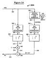
- Figure 3A is a block diagram of a system 300A having fixed compensator gain for reducing near-end echoes and detecting tone signals.
- the system 300A employs a dual-bank BPS Filter and Integration scheme, wherein one filter bank is used to process received (incoming) signals while the other is used to process transmitted (outgoing) signals, and the outputs of the two filter banks are combined to eliminate near-end echoes of the transmitted signals.
- the system 300A includes a conventional system hybrid and line interface 320 (compare Figure 1 ) providing separate lines for received and transmitted data.
- the line interface portion of the system hybrid and line interface 320 is a codec (coder/decoder) which converts analog telephone signals to/from digital form for digital processing by the system 300A.
- a transmitted signal tx(t) on a line 302 is sent out over the PSTN (Phone Line) via the system hybrid and line interface 320.
- Incoming (remote) signals r(t) are received from the phone line by the system hybrid and line interface 320.
- the total signal received by the system hybrid and line interface, and present on the line 304, is a combination of the remote signal r(t) and a near-end echo component ES(t) of the transmitted signal 302.
- the echo component ES(t) is due to imperfect cancellation of all echo components of the transmitted signal (on line 302) in the system hybrid and line interface 320.
- the general object of the present invention is to reduce interference of the echo signal with the decision process of subsequent tonal detection circuitry (not shown).
- the transmit signal on the line 302 is provided to a BPS Filter and Integration block 330.
- An output signal Tx on line 306 from the BPS Filter and Integration block 330 is passed through a magnitude squared functional block 350 which calculates the square of the absolute value of the output 306 of the BPS Filter and Integration block 330 and outputs the signal
- "functional blocks" are elements that can be implemented in hardware or in software.
- the composite remote signal r(t) + ES(t) on the line 304 is provided to another BPS Filter and Integration block 340.
- An output signal R + ES on a line 308 from the BPS Filter and Integration block 340 is passed through a magnitude squared function 360 which calculates the square of the absolute value of the output R + ES of the BPS Filter and Integration block 340, and outputs a signal
- the BPS Filter and Integration block 330 and the squarer 350 form a first filter bank for processing the transmit signal (Tx).
- the BPS Filter and Integration block 340 and the squarer 360 form a second filter bank processing the composite received signal (R+ES).
- the function and operation of the BPS Filter and Integration blocks (330, 340) is described in greater detail hereinbelow with respect to Figure 4 .
- the outputs of the first and second filter banks are processed to eliminate the echo term (ES) from the composite remote signal (R+ES), so that subsequent decoders and the like (not shown) are presented with a "pure" received signal (R).
- 2 of the magnitude squared function 350 is multiplied by a compensator gain coefficient "C" impressed upon input line 312 to a multiplier function 380.
- the multiplication result is a signal on line 314 which is subtracted in a summing function 390 from the output on the line 309 of the magnitude squared function 360 to produce an echo-reduced received signal (Rx) on a line 316.
- the "functions" referred to herein may be implemented in either hardware or in software.
- the band energy of the transmitted and received signals 302 and 304 is measured by the two filter banks (i.e., function blocks 330 and 350 for the transmit signal 302, and function blocks 340 and 360 for receive).
- the two filter banks can be made identical to one another so that a single filter bank can be multiplexed to perform the function of both the transmit filter bank and the receive filter bank. This would save on the amount of storage which would otherwise be required for separate sets of filter coefficients for two discrete filter banks.
- the filter banks behave as bandpass filters, passing only a narrow band of frequencies about a frequency of interest (e.g., a signalling tone).
- the receive filter bank acts as the signal tone detector.
- a sufficient output level at the echo-cancelled receive output Rx on line 316 indicates a "hit" at the selected frequency.
- one filter bank is provided for each tone frequency to be decoded.
- Other implementations are possible, however, wherein one or more (e.g. both) of the filter banks are multiplexed. By multiplexing, a single filter bank can be used to scan more than one tone.
- a fixed delay line can be used to compensate for the analog and digital delays (codec) that are present in the system hybrid and line interface module 320.
- codec analog and digital delays
- a delay-line is not mandatory, because the narrow frequency energy band to which the filters respond makes this method relatively insensitive to delay variations.
- the compensator gain factors are chosen to minimize the amount of transmit signal leak-through based upon known system characteristics.
- an adaptive technique can be employed to calculate dynamically-adjusted compensator gain coefficients.
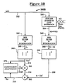
- Such an embodiment of the invention is shown in Figure 3B .
- Figure 3B is a block diagram of a system 300B for near-end echo reduction with adaptive compensation gain, according to the invention. It is identical to the system 300 of Figure 3A in all respects except that a coefficient adaptation block 370 monitors the echo-cancelled receive output signal (Rx) on the line 316 and the output 310 of the magnitude squared function 350, and dynamically "tunes" an adaptive compensator coefficient C' presented on a line 312A to the multiplier 380 to minimize the amount of transmit signal leak-through (cross-talk) in the echo-cancelled received signal output onto the line 316.
- Rx echo-cancelled receive output signal
- cross-talk cross-talk
- adaptation of the compensator gain coefficient (C') on line 312A is accomplished according to the following formula:
- C m+1 C m + ⁇ RX
- 2 ⁇ ⁇ 0 / (
- variable "m" is used as a block number to track the iteration.
- FIG 4 is a block diagram of a BPS (Bandpass) Filter and Integrator 400 (see 330 and 340 in Figures 3A and 3B ), according to an embodiment of the present invention.
- the filter 400 is built around a feedback loop which includes a unit delay 420, a coefficient gain block 430 and summing function 440.
- An output 404 from the summing function 440 is delayed by one unit "D" in the delay block 420.
- the delayed output 408 from the delay block 420 is multiplied by a coefficient P K in the coefficient gain block 430.
- the output of the coefficient gain block 430 is added to an input signal 402 (see 302 and 304 in Figures 3A and 3B ) in the summing function 440 to produce the summing function output 404.
- the echo signal ES is a complex number output by the BPS filter and Integrator 400, which represents the near-end echo portion of the transmit signal (Tx 302 which is also a complex number) which passes through the hybrid (320) and the remote signal (R which is also a complex number) such that the received signal (e.g., composite remote signal on line 304) is R + ES.
- the Tx signal (302) when bandpass filtered, integrated and squared is equal to the magnitude of the transmit signal in the frequency band of interest
- the Rx signal value for subsequent thresholding is obtained by detector decision logic, in the following manner:
- 2
- 2
- the echo reducer changes the error term from
- FIG. 5 is a block diagram of a system 500 for implementing the present invention using a Digital Signal Processor (DSP) wherein a DSP 520 transmits and receives signals over the PSTN via a System Hybrid and Line Interface 510, in much the same manner described hereinabove with respect to Figures 3A and 3B.
- the algorithmic hardware structure depicted in Figure 3B is implemented on the DSP 520 by storing a program in a program memory 530 which represents the component functions of the algorithm.
- Coefficient and variable storage memory 540 is used to store tunable coefficients and to provide memory (history) for the filters.
- the techniques to implement any describable filter function are well known to those of ordinary skill in the art and, therefore, need not be further elaborated upon herein.
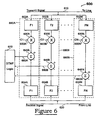
- FIG. 6 shows a multi-tone decoding system 600 utilizing the present inventive technique to detect a plurality of tones on a received signal on a line 620 in the presence of echoes of a transmitted signal on a line 610.
- the multi-tone decoding system 600 includes a plurality of tone detectors 680A, 680B, ... 680N of the type shown and described hereinabove with respect to Figures 3A and 3B , and DTMF logic 670.
- Each tone detector 680A, 680B, ... 680N detects a sinusoidal tone at a different, specific frequency, producing a corresponding detection output on a respective output line 660A, 660B, ... 660N.
- the DTMF logic 670 determines the presence or absence of tones (e.g., combinations of specific tones) by comparing signal magnitudes on the tone detection outputs 660A, 660B... 660N against threshold values above which a tone is deemed to be present.
- the DTMF logic 670 responds to combinations of tones present on the tone detection outputs 660A, 660B, ..., 660N, interpreting such combinations according to a predefined (e.g., conventional) set of tone combinations for which specific significance (i.e., pairs of tones are associated with specific keys on a telephone keypad) is defined.
- Each tone detector 680A, 680B, ..., 680N is connected to receive the transmit signal on the line 610 and to the receive signal on the line 620.
- the transmit signal in each tone detector 680A, 680B, ..., 680N connects to a respective transmit filter and squarer 602A, 602B, ..., 602N (compare 330 combined with 350, Figures 3A and 3B ), and the receive signal in each tone detector 680A, 680B, ..., 680N connects to a respective receive filter and squarer 604A, 604B, ..., 604N (compare 340 combined with 360, Figures 3A and 3B ).
- each tone detector 680A, 680B, ... 680N includes a respective multiplier 630A, 630B, ... 630N (compare 380, Figures 3A and 3B ), which multiplies an output from the respective transmit filter 602A, 602B, ..., 602N by a respective cancellation coefficient C1, C2, ..., CN on lines 650A, 650B, ...
- each transmit filter 602A, 602B, ..., 602N (F1, F2, ... FN) is identical to its respective receive filter 604A, 604B, ..., 604N (F1, F2, ... FN), such that the functions (F) of both the transmit and receive filters may be accomplished in the same filter implementation, i.e., each receive filter 604A, 604B, ..., 604N and each corresponding transmit filter 602A, 602B, ..., 602N can share a single corresponding physical filter implementation.
- each filter can be implemented separately, in a parallel configuration.
Landscapes
- Engineering & Computer Science (AREA)
- Signal Processing (AREA)
- Computer Networks & Wireless Communication (AREA)
- Cable Transmission Systems, Equalization Of Radio And Reduction Of Echo (AREA)
- Telephonic Communication Services (AREA)
- Telephone Function (AREA)
Claims (8)
- Echoabschwächer für Tonsignaldetektoren mit:einer Übertragungsleitung (302), die Sendesignale zu einer Systemgabelschaltung (320) überträgt, die mit einer Telefonleitung verbunden ist;einer Empfangsleitung (304), die entfernte Signale von der Systemgabelschaltung überträgt, wobei die entfernten Signale ein Nahecho der Sendesignale umfassen;einem Mittel (330, 350) zum Bandpassfiltern, Integrieren und Quadrieren der Sendesignale, um ein erstes Ausgangssignal vorzusehen;einem Mittel (340, 360) zum Bandpassfiltern, Integrieren und Quadrieren der entfernten Signale, um ein zweites Ausgangssignal vorzusehen;einem Multiplizierer (380) zum Multiplizieren des ersten Ausgangssignals mit einem Kompensatorverstärkungskoeffizienten und zum Erzeugen eines resultierenden Signals; undeinem Mittel (390) zum Subtrahieren des resultierenden Signals vom zweiten Ausgangssignal und zum Erzeugen eines Empfangssignals, von dem das Nahecho abgeschwächt wurde.
- Echoabschwächer nach Anspruch 1, welcher ferner ein Mittel (370) zum Vorsehen des Kompensatorverstärkungskoeffizienten als Funktion des ersten Ausgangssignals und des vom Addierer erzeugten Empfangssignals umfasst.
- Echoabschwächer nach Anspruch 1, wobei das Mittel zum Filtern, Integrieren und Quadrieren der Sende- und entfernten Signale als einzelnes Filternetzwerk vorgesehen ist, das zwischen den Sendesignalen und den entfernten Signalen im Multiplexbetrieb arbeitet.
- Echoabschwächer nach einem vorangehenden Anspruch, wobei jedes Mittel zum Filtern umfasst:eine Eingangsleitung (402), die mit einem ersten Eingang eines Summierblocks gekoppelt ist, wobei der Summierblock einen Ausgang aufweist;eine Verzögerung (420) mit einem Eingang, der mit dem Ausgang des Summierblocks gekoppelt ist, und mit einem Ausgang;einen Koeffizientenverstärkungs-Multiplizierer (430) mit einem Eingang, der mit dem Ausgang (408) des Verzögerungsblocks verbunden ist, und mit einem Ausgang (410), der mit einem zweiten Eingang des Summierblocks verbunden ist, und iterativ das Ausgangssignal des Verzögerungsblocks mit einer gegebenen Anzahl von Koeffizienten (PK) multipliziert; undein Mittel (406) zum Vorsehen des Ausgangssignals des Summierblocks als Bandpassfilter-Ausgangssignal bei Beendung der iterativen Multiplikation des Ausgangssignals (408) des Verzögerungsblocks mit der gegebenen Anzahl von Koeffizienten (PK).
- Verfahren zum Minimieren einer Echokomponente von einem entfernten Signal, umfassend:Leiten von Sendesignalen von einem Telefonsystem durch eine Systemgabelschaltung zu einer Telefonleitung;Leiten von entfernten Signalen von der Telefonleitung, wobei die entfernten Signale ein Nahecho der Sendesignale umfassen;Filtern, Integrieren und Quadrieren der Sendesignale;Filtern, Integrieren und Quadrieren der entfernten Signale;Multiplizieren der gefilterten und quadrierten Sendesignale mit einem Kompensatorverstärkungskoeffizienten und Erzeugen eines resultierenden Signals; undSubtrahieren des resultierenden Signals von den gefilterten und quadrierten entfernten Signalen, um ein echokompensiertes Empfangssignal zu erzeugen.
- Verfahren nach Anspruch 5, wobei der Kompensatorverstärkungskoeffizient fest ist.
- Verfahren nach Anspruch 5, wobei der Kompensatorverstärkungskoeffizient adaptiv vom gefilterten und quadrierten Sendesignal und vom echokompensierten Empfangssignal abgeleitet wird.
- Verfahren nach Anspruch 5, welches ferner das Durchführen des Filterns und Quadrierens der Sende- und entfernten Signale mit einem einzelnen, im Multiplexbetrieb arbeitenden Filtersatz umfasst, um individuell die Sendesignale und entfernten Signale zu verarbeiten.
Priority Applications (1)
| Application Number | Priority Date | Filing Date | Title |
|---|---|---|---|
| EP01128019A EP1202516B1 (de) | 1995-03-09 | 1996-03-08 | Mehrtondetektorsystem |
Applications Claiming Priority (2)
| Application Number | Priority Date | Filing Date | Title |
|---|---|---|---|
| US40717695A | 1995-03-09 | 1995-03-09 | |
| PCT/US1996/003196 WO1996028897A1 (en) | 1995-03-09 | 1996-03-08 | Band power echo reducer for multifrequency signal detectors |
Related Child Applications (1)
| Application Number | Title | Priority Date | Filing Date |
|---|---|---|---|
| EP01128019A Division EP1202516B1 (de) | 1995-03-09 | 1996-03-08 | Mehrtondetektorsystem |
Publications (2)
| Publication Number | Publication Date |
|---|---|
| EP0759236A1 EP0759236A1 (de) | 1997-02-26 |
| EP0759236B1 true EP0759236B1 (de) | 2003-06-04 |
Family
ID=23610953
Family Applications (2)
| Application Number | Title | Priority Date | Filing Date |
|---|---|---|---|
| EP96910395A Expired - Lifetime EP0759236B1 (de) | 1995-03-09 | 1996-03-08 | BANDLEISTUNGSECHOABSCHWÄCHER FüR MEHRFREQUENZSIGNALDETEKTOREN |
| EP01128019A Expired - Lifetime EP1202516B1 (de) | 1995-03-09 | 1996-03-08 | Mehrtondetektorsystem |
Family Applications After (1)
| Application Number | Title | Priority Date | Filing Date |
|---|---|---|---|
| EP01128019A Expired - Lifetime EP1202516B1 (de) | 1995-03-09 | 1996-03-08 | Mehrtondetektorsystem |
Country Status (3)
| Country | Link |
|---|---|
| EP (2) | EP0759236B1 (de) |
| KR (1) | KR100271508B1 (de) |
| WO (1) | WO1996028897A1 (de) |
Families Citing this family (2)
| Publication number | Priority date | Publication date | Assignee | Title |
|---|---|---|---|---|
| IL149847A (en) * | 2002-05-26 | 2007-07-04 | Amir Llan | Method and device for handling echo in a communication network |
| KR101169433B1 (ko) | 2006-01-19 | 2012-07-27 | 삼성전자주식회사 | VoIP 시스템의 라인 에코 방지 장치 및 그 방법 |
Family Cites Families (5)
| Publication number | Priority date | Publication date | Assignee | Title |
|---|---|---|---|---|
| DE2640551A1 (de) * | 1976-09-09 | 1978-03-16 | Deutsche Bundespost | Frequenzselektive echosperre |
| US4460808A (en) * | 1982-08-23 | 1984-07-17 | At&T Bell Laboratories | Adaptive signal receiving method and apparatus |
| US5001701A (en) * | 1989-08-07 | 1991-03-19 | At&T Bell Laboratories | Subband echo canceler including real time allocation among the subbands |
| CA2116584C (en) * | 1991-08-30 | 1999-01-19 | Vijay R. Raman | Adaptive echo canceller for voice messaging system |
| DE4427124A1 (de) * | 1994-07-30 | 1996-02-01 | Philips Patentverwaltung | Anordnung zur Kommunikation mit einem Teilnehmer |
-
1996
- 1996-03-08 EP EP96910395A patent/EP0759236B1/de not_active Expired - Lifetime
- 1996-03-08 EP EP01128019A patent/EP1202516B1/de not_active Expired - Lifetime
- 1996-03-08 WO PCT/US1996/003196 patent/WO1996028897A1/en not_active Ceased
- 1996-03-08 KR KR1019960706297A patent/KR100271508B1/ko not_active Expired - Fee Related
Also Published As
| Publication number | Publication date |
|---|---|
| EP1202516A2 (de) | 2002-05-02 |
| KR100271508B1 (ko) | 2000-11-15 |
| KR970703070A (ko) | 1997-06-10 |
| EP0759236A1 (de) | 1997-02-26 |
| EP1202516B1 (de) | 2004-08-04 |
| WO1996028897A1 (en) | 1996-09-19 |
| EP1202516A3 (de) | 2003-01-02 |
Similar Documents
| Publication | Publication Date | Title |
|---|---|---|
| US5646991A (en) | Noise replacement system and method in an echo canceller | |
| US5587998A (en) | Method and apparatus for reducing residual far-end echo in voice communication networks | |
| EP0542882B1 (de) | Restecholöschung | |
| US5896452A (en) | Multi-channel echo canceler and method using convolution of two training signals | |
| JP4090505B2 (ja) | エコー抑制装置及びエコー打消装置の非直線的プロセッサ | |
| US5390244A (en) | Method and apparatus for periodic signal detection | |
| EP0878060B1 (de) | Verfahren und anordnung zur durchführung von echokompensation in einem übertragungsnetzwerk unter verwendung eines gemischten adaptiven balancefilters nach dem verfahren des kleinsten quadratischen fehlers | |
| JPS61127234A (ja) | エコ−・キヤンセラの制御方式 | |
| US5247512A (en) | Echo canceller | |
| CA2162571C (en) | Echo canceler and method for learning for the same | |
| US5631957A (en) | Band-energy near-end echo reducer for tonal signalling detectors | |
| WO2002062046A1 (en) | Line echo canceller scalable to multiple voice channel/ports | |
| US8369511B2 (en) | Robust method of echo suppressor | |
| EP0759236B1 (de) | BANDLEISTUNGSECHOABSCHWÄCHER FüR MEHRFREQUENZSIGNALDETEKTOREN | |
| US6751313B2 (en) | Method and apparatus for an improved echo canceller | |
| CA2494386C (en) | Narrow band tone detection in echo canceling system | |
| JPH07303072A (ja) | ダブルトーク検出方法および装置 | |
| JP3304609B2 (ja) | エコーキャンセラ学習方法 | |
| JP2585786B2 (ja) | 双方向通話検出方式、それを用いる反響消去装置および拡声電話機 | |
| JPH11331047A (ja) | 圧伸器を有する多重チャネルエコ―消去装置 | |
| JPH07303068A (ja) | エコーキャンセラ学習方法 | |
| WO1994000944A1 (en) | Method and apparatus for ringer detection | |
| JPH02264524A (ja) | エコーキャンセラ | |
| HK1015215B (en) | Network echo canceller | |
| JPH07303071A (ja) | ダブルトーク検出方法 |
Legal Events
| Date | Code | Title | Description |
|---|---|---|---|
| PUAI | Public reference made under article 153(3) epc to a published international application that has entered the european phase |
Free format text: ORIGINAL CODE: 0009012 |
|
| AK | Designated contracting states |
Kind code of ref document: A1 Designated state(s): DE FR GB |
|
| 17P | Request for examination filed |
Effective date: 19970315 |
|
| 17Q | First examination report despatched |
Effective date: 20010629 |
|
| GRAH | Despatch of communication of intention to grant a patent |
Free format text: ORIGINAL CODE: EPIDOS IGRA |
|
| GRAH | Despatch of communication of intention to grant a patent |
Free format text: ORIGINAL CODE: EPIDOS IGRA |
|
| GRAA | (expected) grant |
Free format text: ORIGINAL CODE: 0009210 |
|
| AK | Designated contracting states |
Designated state(s): DE FR GB |
|
| PG25 | Lapsed in a contracting state [announced via postgrant information from national office to epo] |
Ref country code: FR Free format text: LAPSE BECAUSE OF FAILURE TO SUBMIT A TRANSLATION OF THE DESCRIPTION OR TO PAY THE FEE WITHIN THE PRESCRIBED TIME-LIMIT Effective date: 20030604 |
|
| REG | Reference to a national code |
Ref country code: GB Ref legal event code: FG4D |
|
| REF | Corresponds to: |
Ref document number: 69628515 Country of ref document: DE Date of ref document: 20030710 Kind code of ref document: P |
|
| PGFP | Annual fee paid to national office [announced via postgrant information from national office to epo] |
Ref country code: GB Payment date: 20040303 Year of fee payment: 9 |
|
| PGFP | Annual fee paid to national office [announced via postgrant information from national office to epo] |
Ref country code: FR Payment date: 20040318 Year of fee payment: 9 |
|
| PLBE | No opposition filed within time limit |
Free format text: ORIGINAL CODE: 0009261 |
|
| STAA | Information on the status of an ep patent application or granted ep patent |
Free format text: STATUS: NO OPPOSITION FILED WITHIN TIME LIMIT |
|
| 26N | No opposition filed |
Effective date: 20040305 |
|
| EN | Fr: translation not filed | ||
| PG25 | Lapsed in a contracting state [announced via postgrant information from national office to epo] |
Ref country code: GB Free format text: LAPSE BECAUSE OF NON-PAYMENT OF DUE FEES Effective date: 20050308 |
|
| GBPC | Gb: european patent ceased through non-payment of renewal fee |
Effective date: 20050308 |
|
| PGFP | Annual fee paid to national office [announced via postgrant information from national office to epo] |
Ref country code: DE Payment date: 20080430 Year of fee payment: 13 |
|
| PG25 | Lapsed in a contracting state [announced via postgrant information from national office to epo] |
Ref country code: DE Free format text: LAPSE BECAUSE OF NON-PAYMENT OF DUE FEES Effective date: 20091001 |