EP0759358A2 - Correction des bandes avancées pas à pas en registre - Google Patents
Correction des bandes avancées pas à pas en registre Download PDFInfo
- Publication number
- EP0759358A2 EP0759358A2 EP96113476A EP96113476A EP0759358A2 EP 0759358 A2 EP0759358 A2 EP 0759358A2 EP 96113476 A EP96113476 A EP 96113476A EP 96113476 A EP96113476 A EP 96113476A EP 0759358 A2 EP0759358 A2 EP 0759358A2
- Authority
- EP
- European Patent Office
- Prior art keywords
- eyemark
- web
- bag
- disposed
- motor
- Prior art date
- Legal status (The legal status is an assumption and is not a legal conclusion. Google has not performed a legal analysis and makes no representation as to the accuracy of the status listed.)
- Granted
Links
Images




Classifications
-
- B—PERFORMING OPERATIONS; TRANSPORTING
- B31—MAKING ARTICLES OF PAPER, CARDBOARD OR MATERIAL WORKED IN A MANNER ANALOGOUS TO PAPER; WORKING PAPER, CARDBOARD OR MATERIAL WORKED IN A MANNER ANALOGOUS TO PAPER
- B31B—MAKING CONTAINERS OF PAPER, CARDBOARD OR MATERIAL WORKED IN A MANNER ANALOGOUS TO PAPER
- B31B70/00—Making flexible containers, e.g. envelopes or bags
-
- B—PERFORMING OPERATIONS; TRANSPORTING
- B31—MAKING ARTICLES OF PAPER, CARDBOARD OR MATERIAL WORKED IN A MANNER ANALOGOUS TO PAPER; WORKING PAPER, CARDBOARD OR MATERIAL WORKED IN A MANNER ANALOGOUS TO PAPER
- B31B—MAKING CONTAINERS OF PAPER, CARDBOARD OR MATERIAL WORKED IN A MANNER ANALOGOUS TO PAPER
- B31B70/00—Making flexible containers, e.g. envelopes or bags
- B31B70/006—Controlling; Regulating; Measuring; Safety measures
-
- B—PERFORMING OPERATIONS; TRANSPORTING
- B31—MAKING ARTICLES OF PAPER, CARDBOARD OR MATERIAL WORKED IN A MANNER ANALOGOUS TO PAPER; WORKING PAPER, CARDBOARD OR MATERIAL WORKED IN A MANNER ANALOGOUS TO PAPER
- B31B—MAKING CONTAINERS OF PAPER, CARDBOARD OR MATERIAL WORKED IN A MANNER ANALOGOUS TO PAPER
- B31B70/00—Making flexible containers, e.g. envelopes or bags
- B31B70/02—Feeding or positioning sheets, blanks or webs
- B31B70/10—Feeding or positioning webs
-
- B—PERFORMING OPERATIONS; TRANSPORTING
- B31—MAKING ARTICLES OF PAPER, CARDBOARD OR MATERIAL WORKED IN A MANNER ANALOGOUS TO PAPER; WORKING PAPER, CARDBOARD OR MATERIAL WORKED IN A MANNER ANALOGOUS TO PAPER
- B31B—MAKING CONTAINERS OF PAPER, CARDBOARD OR MATERIAL WORKED IN A MANNER ANALOGOUS TO PAPER
- B31B2160/00—Shape of flexible containers
- B31B2160/10—Shape of flexible containers rectangular and flat, i.e. without structural provision for thickness of contents
Definitions
- This invention relates to plastic bag fabricating machines and more particularly to systems for controlling operation of such machines.
- the graphic material is printed onto the plastic web in regularly spaced locations or fields, and it is necessary to ensure that the web is cut and sealed only at precise locations between the fields in order to insure proper placement of the printed matter on the finished bag.
- One technique for ensuring that the web is cut and sealed at the proper locations is to advance the web by a predetermined distance, or draw length, equal to the spacing of the printed fields. However, minor errors, resulting from stretching or shrinkage of the web as it is printed and wound onto and off of the supply roll, accumulate and gross misalignment can occur over time as the bag fabricating machine operates.
- Another technique for ensuring that the web is cut and sealed at the desired locations between adjacent printed fields is to print regularly spaced indexing marks or "eyemarks" on the web before the web is fed into the bag fabricating machine.
- An optical sensor detects the passage of each eyemark by a predetermined location and signals the machine when to stop, cut and seal the web. However, it is often desired to include printed matter between successive eyemarks.
- the optical sensor In order to avoid sensing other marks which appear to be eyemarks, it is preferred to enable the optical sensor only over a small interval or "window" in which the eyemark is expected to be seen.
- This technique is effective in correcting minor systematic errors in alignment (such as, an intermittent lengthening or shortening of the actual distance between eyemarks). Progressive errors can arise as a result of varying tensions as the web is wound and unwound from the supply roll, and this can result In the eyemarks falling outside of the sensing window. These types of errors can cause improper alignment of the printed matter on the finished bags.
- U.S. Patent No. 5,000,725 Another method of correcting the cutting and sealing of individual bags is disclosed in U.S. Patent No. 5,000,725, owned by applicant's assignee.
- the control system disclosed in U.S. Patent No. 5,000,725 functions to sense the actual spacing between a predetermined number of successive eyemarks. In the event the distances of such actual spacings shows a trend to deviate from the nominal draw length, the control system functions to change the nominal draw length to be substantially equal to the average of the actual spacings sensed. The control system helps ensure that the eyemarks continue to appear within the scanning window even though the actual spacings between eyemarks tend to deviate from the nominal draw length.
- FIG. 1 there is shown a flow chart diagram regarding the operation of the control system disclosed in U.S. Patent No. 5,000,725.
- the control system after receiving an instruction to start operation, first reads and stores the nominal draw length entered by the system operator, as indicated by blocks 10 and 12, respectively.
- the control system then awaits the generation of "go" signal from the CPU located in a computer control circuit, as indicated by block 14.
- a servo motor for driving the draw rolls starts and the system monitors the advancement of the web by counting pulses from an encoder directly coupled to the servo motor until it is determined that the web has been advanced to within a specified distance (such as one-half inch) of the current calculated draw length as shown by block 16. It will be appreciated that the specified distance sets the width of the scanning "window.”
- an optical scanner is enabled and both the optical scanner and the servo motor are monitored until either the leading edge of the eyemark is detected by the scanner or the servo motor stops running, as shown by blocks 18 and 20, respectively.
- an encoder counter is set to zero and the status of the servo motor is ascertained, as shown by blocks 22 and 24, respectively.
- R1 represents the length by which the leading edge of the eyemark is displaced from the optical scanner when the web has stopped.
- the program determines whether the value of R1 is approximately zero (i.e., less than 0.03 inches), as shown by block 28. When an eyemark does appear within the scanning window, R1 will be non-zero. The program then determines the non-zero value of R1 as shown by block 30. If R1 is less than 0.2 inches or Is greater than 0.3 inches, for example, a variable constant R3 is incremented by the print repeat length PR, as shown by block 32.
- the print repeat length PR which is equal to DL+Y-X, represents the draw length of the next bag forming cycle where X is the distance the leading edge of the eyemark went past the scanner during the current bag-forming cycle, Y is the distance the leading edge of the next preceding eyemark went past the scanner during the immediately preceding bag-forming cycle, DL is the total distance the web has been advanced for formation of the current bag and PR is the distance between successive eyemarks.
- the variable constant R2 is incremented by one, as also shown in block 32, and serves to indicate the number of times that an eyemark has fallen within the scanning 'window" but not within the desired range of the "window" midpoint.
- R2 is next compared against a predetermined constant representing the number of consecutive times that R1 fails to fall within the desired range of the midpoint, as shown by block 34.
- a predetermined constant representing the number of consecutive times that R1 fails to fall within the desired range of the midpoint.
- ten such consecutive failures can occur before the system takes action to change or update the nominal draw length.
- the next or calculated draw length DL is set equal to the nominal repeat length, minus R1, and plus 0.25 inches, as shown by block 36, For this cycle, however, R2 and R3 are not set equal to zero and these values are retained as the system retums to await initiation of the next bag forming cycle.
- variable constant R2 will eventually equal the predetermined constant (ten In the illustrated example).
- variable constant R3 will substantially equal the sum total of the actual distances between eyemarks over the preceding ten consecutive bag fabricating cycles when this occurs, the system calculates the average actual distance between consecutive eyemarks and changes the nominal draw length to the calculated average. Thereafter, the variable constants R2 and R3 are set to zero and the system recycles to await initiation of the next bag fabricating cycle, as shown by block 38.
- the leading edge of the eyemark should appear substantially midway between the limits or edges of the scanning "window."
- R1 having a value of substantially 0.25 inches or one-half the scanning window width.
- R2 and R3 are set to zero, as shown by block 40.
- the next draw length is set equal to the nominal draw length minus the current R1 value plus one-half the width of the scanning "window", as shown by block 36.
- the value of the next draw length is set to the value of the current draw length plus half the scanning window of 0.25 inches, as shown by block 42.
- the printed eyemark is advanced when the eyemark gets out of the scanning window, the window being, for example, 0.5 inches and the eyemark gains on the scanning device until the mark is located within the window.
- the film can get out of register by a large amount (i.e., the eyemark may be a half an inch or more away from the edge of the scanner when a given bag is being cut).
- the prior art systems may not fully compensate for the error in film cutting because the scanner may not properly be able to read the eyemarks. This condition could occur for several reasons. For example, the printed eyemarks may have wandered from under the scanning device, there may have been a temporary malfunction of the scanning device, there may be a splice in the film, or the eyemarks may not be printed for a section of the film.
- the bag machine operator may have to do one of two things.
- the operator may first have to wait for the regular registration means to advance the film by a small amount for each bag until the mark again appears in the scanning window.
- This could take forty or more bags before the marks would get back in synchronization within the scanning window.
- these forty or more bags may be irregular bags.
- the more commonly used involves the operator stopping the machine, advancing the film until the printed mark is under the scanner, lowering the cutting/sealing device to cut the film, and then restarting the machine. These alternatives are time consuming and may slow down the operation. It is therefore desirable to have a correction system which may correct large errors when cutting webs of film.
- a method of correcting the advancement of lengths of material having regularly spaced eyemarks thereon comprising the steps of: determining a failure to sense an eyemark disposed on the material; activating a sensor for sensing the passage of a first succeeding eyemark disposed on the material, the sensor being enabled for an open scanning window; activating the sensor for a portion of a length between the regularly spaced eyemarks after the first succeeding eyemark has been sensed; determining a correction distance between the first succeeding eyemark and a location when the material is stopped; and advancing the material by the correction distance; wherein the material is advanced such that a second succeeding eyemark is disposed around the sensor when the sensor Is activated for said portion of a length between the regularly spaced eyemarks.
- a method of correcting lengths of bags being formed from a web of material comprising the steps of: measuring a correction distance from which a leading edge of an eyemark disposed on the web is displaced from a scanner when the web has temporarily stopped for a time when forming a leading bag, the temporary stopping time being a period between a successive continuous formation of individual bags; advancing the web by the correction distance for forming a shorter first trailing bag; and advancing the web for forming a successive trailing bag by a nominal draw length, the successive trailing bag being formed after the shorter first trailing bag,
- a method of correcting lengths of bags being formed from a web of material comprising the steps of: enabling a scanner; detecting whether the web of material is moving; detecting an eyemark disposed on the web by the scanner; measuring a correction distance from which a leading edge of the eyemark is displaced from the scanner when the web has temporarily stopped for a time when forming a leading bag; the temporary stopping time being a period between a successive continuous formation of individual bags; advancing the web by the correction distance for forming a shorter first trailing bag; and advancing the web for forming a successive trailing bag by a nominal draw length, the successive trailing bag being formed after the shorter first trailing bag.
- a correction system for correcting the advancement of lengths of material having regularly spaced eyemarks thereon comprising: means for determining a failure to sense an eyemark disposed on the material; starter means for activating a sensor for sensing the passage of a first succeeding eyemark disposed on the material, the sensor being enabled for an open scanning window; means for activating the sensor for a portion of a length between said regularly spaced eyemarks after the first succeeding eyemark has been sensed; means for determining a distance between the first succeeding eyemark and a location when the material is stopped; means for advancing the material by the distance; wherein the material is advanced such that a second succeeding eyemark is disposed around the sensor when the sensor is activated for the portion of a length between the regularly spaced eyemarks.
- a correction system for correcting lengths of bags being formed from a web of material comprising: means for determining a failure to sense an eyemark disposed on the web when producing a leading bag; starter means for activating a sensor for sensing the passage of an eyemark disposed on the web, the sensor being enabled for an open scanning window; means for determining a distance between the eyemark and a location when the web is stopped for cutting and sealing; means for advancing the web by the distance for forming a shorter trailing bag; and means for forwarding the web for forming a successive trailing bag by a nominal draw length.
- the means for determining a distance may, for example, comprise an encoder coupled to a motor, the motor being disposed on a bag making machine, the encoder being coupled to a computer control circuit.
- the means for advancing may, for example, comprise a motor controller coupled to the computer control circuit, the motor being further coupled to the motor controller and draw rolls disposed on the bag making machine, the draw rolls being operatively connected to the motor.
- FIG. 1 is a flow chart diagram of a prior art system for correcting the placement of a plastic web.
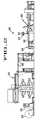
- FIG. 2 is a side elevation view of a bag fabricating system of the present invention including a bag machine operable to form plastic bags from plastic web.
- FIG. 3 is a simplified block diagram of a correction system of the present invention.
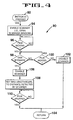
- FIG. 4 is a flow chart diagram useful in understanding the operation of the correction system for correcting large errors in the placement of the web when cutting and sealing the same for forming bags.
- FIGS. 5A and 5B is a flow chart diagram useful in understanding the operation of the correction system in conjunction with a program for feeding film for continuously making bags.
- FIGS. 6A-6F is a diagrammatic view of the web of film illustrating the operation of the correction system.
- a system 50 for automatically fabricating plastic bags from a continuous plastic web 52 is illustrated in Figure 2.
- the system 50 includes a supply roll 54 containing the web 52, and an optional print mechanism 56 for repetitively printing graphic material at regularly spaced locations on the web 52.
- the system 50 further includes a bag machine 58 for transversely cutting and sealing the web 52 to form individual plastic bags, and an optional stacker mechanism 60 for stacking the bags formed by the bag machine 58.
- a user-operable control panel 62 provides user-control over the automatic bag fabricating system 50.
- a starter 61 which may be, for example, a button on the control panel 62 for activating the correction system of the present invention.
- the correction system 63 is shown.
- a plurality of eyemarks 72 are printed at regular intervals along the edge of the web 52, and an optical scanner or sensor 74 photoelectrically senses the passage of each eyemark 72.
- the optical scanner 74 is generally not continuously enabled, but rather, is enabled only for brief periods during which it is expected that the eyemark 72 should appear. That is, the optical scanner 74 Is turned on during a specific "window" of the bag length, typically the last one-half inch of each advancement of the web 62. In this manner, the optical scanner 74 is only responsive to eyemarks 72 appearing within the scanning window. However, when starter 61 is depressed, the optical scanner 74 becomes continuously enabled until the correction of the bag lengths is complete, as will be described.
- the computer controls circuit 84 may, for example, only read the signals generated by the scanner 74 during the last half inch of a bag being formed during normal operation.
- enabling or activating a scanner means either reading the signal generated by the scanner 74 or tuming on the scanner 74 to generate a signal so that it may be input to the computer control circuit 84.
- the correction system 63 comprises a control system 76 which preferably includes control panel 62 with a starter 61 and optical scanner 74.
- the correction system 63 further comprises an electrical servo motor 78 disposed on the bag machine 58.
- the servo motor 78 is coupled, by means of a belt 80 or similar arrangement, to the draw rolls 68.
- the control system 76 further includes an encoder 82 which is directly coupled to the motor 78 and which functions to provide electrical pulses indicative of the rotation of the motor shaft (e.g., 4000 pulses per motor revolution).
- the signals generated by the encoder 82, the control panel 62 including the starter 61, and the optical scanner 74, are fed as inputs to computer control circuit 84.
- the computer control circuit 84 respond to these Inputs by instructing a motor controller 86 to drive the motor 78 so as to advance the web 52 a sufficient distance to provide a desired orientation of the eyemarks 72 relative to the transverse cut and seal bar 70.
- the computer control circuit 84 which may include a central processing unit, may also include a resetable counter 84a which counts the pulses developed by the encoder 82.
- control system 76 of the present invention is preferably implemented utilizing microprocessor-based circuitry in conjunction with suitable programming.
- One possible program 90 for implementing the correction system 13 of the present invention is shown in Figure 4. Program 90 may correct large errors in the placement of the web when cutting and sealing the same for forming bags.
- the operator may, for example, depress a button 61 disposed on the control panel 62, as Indicated by block 92.
- the program 90 then enables the scanner, opening the scanning window for the entire length of the bag to be formed (as opposed to opening up the scanning window for the last half inch of the bag), as indicated by block 94.
- the program 90 then watts for the film 52 to start moving, as indicated by block 96. This temporary stopping time is the time period between a successive continuous formation of individual bags. As a result, the operator does not have to tum off the machine in order to affect correction of the web 12 length.
- the program 90 then waits for ether the scanner 74 to detect an eyemark 72 or for the film 52 to stop moving, as indicated by blocks 98 and 100, respectively. If the film 52 has stopped before the scanner 74 sees an eyemark 72, then the program 90 simply reverts back to the standard registration routine after the scanner 34 has been disabled, indicated by blocks 104 and 102 respectively. The film 52 may stop before the scanner sees an eyemark 72 where, for example, the film 52 falls to have eyemarks 72 printed thereon.
- R1 is the correction distance which is then used as the next length of film to be fed ahead, forming a shorter trailing bag, as indicated by block 108.
- the measuring of the correction distance R1 may comprise encoder 82 which may be coupled to servo motor 78 disposed on the bag-making machine 58 and operable to generate a signal indicative of motor revolution.
- the shorter trailing bag should have its eyemark 72 within the scanning window, After the shorter tailing bag is formed (i.e., when the film has stopped as indicated by block 110), the program reverts back to the standard registration routine, as shown by block 104. Thereafter, a main program may produce successive trailing bags having a the desired or nominal draw length.
- the bag making machine 58 does not have to be shut off when correcting the large error in the placement of the web relative to the cutting and sealing bar 70.
- One possible standard registration routine program 120 having a correction subroutine 90 is exemplified by the flow chart diagram of Figures 5A and 5B. Similar items have been labeled similarly for purposes of clarity. Further, for purposes of clarity, subroutine 90, which is illustrated as a blook In Figure 5B, is shown together with a main program 120, the main program including all items except for subroutine 90.
- the main program 120 initially reads and stores the draw length and once a go signal is generated, the system monitors the advancement of the web until the scanning window is reached (i.e., the last half of an inch of the current calculated draw length in the illustrated example), as shown by blocks 10-16. Similarly, the program then proceeds to measure the value R1, via blocks 18-26.
- the program then forwards to block 28.
- the value of R1 will be substantially zero. If R1 is substantially zero (i.e., less than 0.03 inches in the example illustrated), then that may mean that the web was stopped for sealing and cutting at approximately where the scanner 34 sensed the eyemark 32. Alternatively, it may mean that the eyemark 32 was not sensed during the scanning window.
- the program forwards to block 42 if the starter 61 is not, for example, depressed, then the correction systern 73 increases the next repeat length by a predetermined increment, such as half the scanning window or 0.25 inches in the illustrated example, and the system enters an idle to await the generation of a "go" signal.
- a predetermined increment such as half the scanning window or 0.25 inches in the illustrated example
- the control system 76 will advance the next draw length by an additional 0.25 inches.
- the eyemark 32 associated with the formation of a given bag should shortly appear within the scanning window.
- subroutine 90 may be called.
- the scanner is enabled for the entire length of the bag to be formed and the subroutine 90 waits for the film to start moving, as indicated by blocks 92-96. If an eyemark 72 is detected, then the scanner 74 is disabled, as indicated by block 106. The exact distance at which the eyemark was seen is recorded as R1 and this value is then used as the next length of film to be fed ahead, forming a shorter trailing bag, as indicted by block 108. The shorter trailing bag should have its eyemark 72 within the scanning window once the film has stopped, indicated by block 110. After the shorter tailing bag is formed, the program reverts back to the main program 120.
- the subroutine 90 forwards to the main program 120 so that it may proceed with the next bag fabricating cycle, such as at the point where it awaits for a "go' signal, as indicated by block 14.
- the control system 76 would be ready to count the next movement of the web for forming a next bag.
- the subroutine 90 simply reverts back to the standard registration routine or main program 120 after the scanner 34 has been disabled. That is, the subroutine 90 would proceed to the main program 120 so that it may proceed with the next fabricating cycle.
- the control system 76 determines what range the value R1 falls within, as indicated by block 30. Where the value of R1 is, for example, less than 0.2 inches (but greater than a nominal amount such as 0.03 inches) or greater than 0.3 inches, the control system counts the number of times this would occur, as indicated by block 32. If the number of times would be less than a given number, say ten, the control system sets the next draw length equal to the draw length plus half the scanning window minus the value of R1, as indicated by blocks 34 and 36.
- the control system sets the next draw length as the running average for the past ten draw lengths where R1 is less than 0.2 inches (but greater than 0.03 inches) or greater than 0.3 inches, as indicated by block 38.
- the running average preferably does not change if the value of R1 is between 0.2 inches and 0.3 inches prior to reaching the required ten times, as indicated by block 40.
- the draw length may be set to the value PR plus half the scanning width minus the value of R1, as shown by block 36. Then, the program retums to the point where it awaits for another "go" signal to begin, as indicated by block 14.
- the large correction program 90 is a subroutine disposed in the CPU of the computer control circuit 84.
- This subroutine may, for example, be called when the normal operating program for feeding the web 52 no longer senses-the eyemarks 72 for a given scanning window.
- the subroutine 90 is activated by an operator by depressing button 61 on the control panel 62.
- the subroutine 90 may be automatically called if an eyemark in block 28 is not sensed a given number of times such as five or any specific number of times that an operator may input.
- the main program would call subroutine 90 to provide correction of the placement of the web 52 relative to the eyemarks 72.
- the starter 61 would comprise a means for sensing the failure of a mark a given number of times for calling the correction program 90 disposed in the computer control circuit 84.
- FIG. 6A-6F there is shown a diagrammatic view of a web of film 52 illustrating the operation of the correction system 63.
- the eyemark 72 for a bag 1 to be formed has stopped more than 0.5 inches ahead of the scanner 74.
- Figure 6B shows how the main program 120 forwards the web 52 by a nominal bag length plus 0.25 inches so that the eyemark 72 may now, for example, be 0.75 inches ahead of the scanner when forming a second bag 2.
- Figure 6C shows how the bag making machine 58 continues to make a third bag 3 having a nominal bag length plus 0.25 Inches. As a result, the eyemark 72 may now be one inch ahead of the scanner 74.
- Figure 6D shows how the subroutine 90 has been called after the formation of bag 6 by preferably depressing a starter button 61 during, for example, the formation of bag 6.
- the web 52 starts to move so that the encoder 82 may count the distance R1 which is the distance from when the web stopped moving until the point where an eyemark 72 is detected. Otherwise, the program will wait until that given bag is formed before it will activate the subroutine so that the value of R1 may be measured.
- the scanner 74 is enabled for the entire bag length (i.e., an open window). As shown by Figure 6E, the value R1 is measured, R1 being the correction distance. Then a short trailing bag 7' is formed, the short bag having a length equal to the correction distance R1, as shown in Figure 6F. As a result, the appropriate eyomark 72 will then be back in the scanning window. Thereafter, the system may resume normal registration control which may be performed by program 120 so that the next bag 8 having a nominal or desired draw length may be formed.
- the nominal draw length may be, for example, substantially equal to an average of actual measured spacing between successive ones of the eyemarks plus or minus a measured error quantity determined during the previous draw plus a portion of a scanning zone between the eyemarks, as disclosed in U.S. Patent No. 5,000,725, which is incorporated herein by reference.
- the correction system 63 comprises a means for determining a failure to sense an eyemark 72 disposed on a material 52, such as an optical scanner or sensor 74 and a computer control circuit 84 and means for activating the sensor 74 for sensing the passage of a first succeeding eyemark 72 disposed on the material 52, the sensor 74 being enabled for an open scanning window. That is, the sensor is enabled until, for example, a second succeeding eyemark 72 is detected as opposed to only enabling a sensor for a set portion of a length between regularly spaced eyemarks such as, for example, the last half an inch of a bag being formed.
- the correction system 63 further comprises means for activating the sensor 74 for a portion of a length between the regularly spaced eyemarks 72 after the first succeeding eyemark has been sensed (i.e., the correction system enables the sensor 74 for a portion of a length between the regularly spaced eyemarks ).
- the correction system 63 also comprises means for determining a correction distance R1 between the first succeeding eyemark 72 and a location when said material is stopped.
- the means for determining a correction distance may comprise an encoder 82 coupled to a motor 78.
- the correction system also comprises a means for advancing the material 52 by the correction distance R1, which may be, for example, a motor controller 86 coupled to the computer control circuit 84.
- the material 52 may be advanced such that a second succeeding eyemark 72 is disposed around the sensor 74 when said sensor is activated for the portion of a length between the regularly spaced eyemarks 72.
- the correction system is used in conjunction with film or other material having no printed material 67 in the region where the scanner 74 may sense such printed material. That is, preferably there is no printed material other than the eyemarks 72 where in the region where the scanner is sensing. Otherwise, when the starter 61 is activated, the system 50 may forward the indexing to the printed material sensed because block 94 of Figures 4 and 5B enables the scanner 74 until an eyemark 72 is sensed or the web 52 has stopped moving. Of course, printed material may be located on the material 52 in a region where the scanner 74 does not sense.
Landscapes
- Making Paper Articles (AREA)
- Controlling Rewinding, Feeding, Winding, Or Abnormalities Of Webs (AREA)
Applications Claiming Priority (2)
| Application Number | Priority Date | Filing Date | Title |
|---|---|---|---|
| US51800195A | 1995-08-22 | 1995-08-22 | |
| US518001 | 1995-08-22 |
Publications (3)
| Publication Number | Publication Date |
|---|---|
| EP0759358A2 true EP0759358A2 (fr) | 1997-02-26 |
| EP0759358A3 EP0759358A3 (fr) | 1998-01-07 |
| EP0759358B1 EP0759358B1 (fr) | 2001-11-21 |
Family
ID=24062120
Family Applications (1)
| Application Number | Title | Priority Date | Filing Date |
|---|---|---|---|
| EP96113476A Expired - Lifetime EP0759358B1 (fr) | 1995-08-22 | 1996-08-22 | Correction des bandes avancées pas à pas en registre |
Country Status (8)
| Country | Link |
|---|---|
| US (1) | US5695106A (fr) |
| EP (1) | EP0759358B1 (fr) |
| JP (1) | JP2829723B2 (fr) |
| AU (1) | AU718388B2 (fr) |
| BR (1) | BR9603516A (fr) |
| CA (1) | CA2183924A1 (fr) |
| DE (1) | DE69617136T2 (fr) |
| ES (1) | ES2168421T3 (fr) |
Cited By (4)
| Publication number | Priority date | Publication date | Assignee | Title |
|---|---|---|---|---|
| EP0881062A3 (fr) * | 1997-05-30 | 2000-07-26 | Shikoku Kakoki Co., Ltd. | Installation pour la fabrication de récipients d'emballage et procédé de la production-II |
| EP0881063A3 (fr) * | 1997-05-30 | 2000-11-15 | Shikoku Kakoki Co Ltd | Installation pour la fabrication de récipients d'emballage et procédé de la production-I |
| EP1020390A3 (fr) * | 1999-01-12 | 2001-12-19 | ELBA S.p.A. | Calandre d'alimentation dans des machines à souder pour matériau plastique |
| CN117719210A (zh) * | 2024-01-19 | 2024-03-19 | 杭州数创自动化控制技术有限公司 | 一种复合膜制袋机光电扫描定位方法 |
Families Citing this family (16)
| Publication number | Priority date | Publication date | Assignee | Title |
|---|---|---|---|---|
| DE19740222A1 (de) * | 1997-09-12 | 1999-03-25 | Boewe Systec Ag | Vorrichtung zum Führen einer Endlospapierbahn |
| US6106448A (en) * | 1998-08-04 | 2000-08-22 | Hosokawa Yoko Co., Ltd. | Package material processing machine |
| US6206263B1 (en) * | 1999-05-13 | 2001-03-27 | Gerber Scientific Products, Inc. | Material advance tracking system |
| US6744515B1 (en) * | 1999-10-25 | 2004-06-01 | Totani Corporation | Heat seal position measurement device for plastic film |
| US6561962B1 (en) * | 2000-03-10 | 2003-05-13 | Converting Systems, Inc. | Line plastic bag machine |
| US6824638B1 (en) * | 2000-07-27 | 2004-11-30 | 3M Innovative Properties Company | Graphic image film registration systems and methods |
| US7022057B2 (en) * | 2000-12-20 | 2006-04-04 | Water-Line Sa | Device for manufacturing packing bags |
| KR20030086619A (ko) * | 2001-03-30 | 2003-11-10 | 지멘스 악티엔게젤샤프트 | 테이핑된 전기 부품을 공급하기 위한 장치 및 방법 |
| US7013803B2 (en) | 2002-02-06 | 2006-03-21 | Quad/Tech, Inc. | Color registration control system for a printing press |
| US7253929B2 (en) * | 2002-02-06 | 2007-08-07 | Quad/Tech, Inc. | Camera assembly for a printing press |
| JP2007302383A (ja) * | 2006-05-10 | 2007-11-22 | Horizon International Inc | 紙折装置 |
| US9221226B2 (en) * | 2012-04-09 | 2015-12-29 | Xerox Corporation | Personalized packaging production system |
| TWM448450U (zh) * | 2012-05-30 | 2013-03-11 | yao-zhang Lin | 可作淋膜編織袋貼合包底之全自動製袋機 |
| JP2023503837A (ja) * | 2019-11-13 | 2023-02-01 | テトラ ラバル ホールディングス アンド ファイナンス エス エイ | 開口デバイスをパッケージ材料のウェブに付加するためのユニット及び方法 |
| WO2022074420A1 (fr) * | 2020-10-05 | 2022-04-14 | Maverick International Pty Ltd | Agencement de fabrication de récipient souple |
| IT202400006760A1 (it) * | 2024-03-26 | 2025-09-26 | Tetra Laval Holdings & Finance | Metodo e unita' per l'applicazione di dispositivi di apertura su un nastro di materiale da confezionamento |
Family Cites Families (15)
| Publication number | Priority date | Publication date | Assignee | Title |
|---|---|---|---|---|
| SE400523B (sv) * | 1975-12-19 | 1978-04-03 | Ziristor Ab | Sett att vid en forpackningsmaskin avlesa fotocellmarkeringar pa en materialbanas dekorsida jemte anordning for genomforande av settet |
| JPS57121548A (en) * | 1980-10-17 | 1982-07-29 | Taiyo Shokai:Kk | Method and device to convey double belt of wrapping material |
| US4459885A (en) * | 1980-11-20 | 1984-07-17 | Owens-Illinois, Inc. | Registration control for a label cutoff apparatus |
| US4485949A (en) * | 1982-08-23 | 1984-12-04 | Xerox Corporation | Controlled frictional feeding of computer forms web |
| JPS59156773A (ja) * | 1983-02-28 | 1984-09-06 | Sato :Kk | 連続札印字機の札移送装置 |
| SE8600365L (sv) * | 1986-01-28 | 1987-07-29 | Tetra Pak Int | Sett och anordning for frammatning av en materialbana |
| US4781317A (en) * | 1986-08-29 | 1988-11-01 | Adolph Coors Company | Phasing control system for web having variable repeat length portions |
| US4809188A (en) * | 1986-10-17 | 1989-02-28 | Spartanics, Ltd. | Strip feeding and control system |
| US5000725A (en) * | 1988-11-07 | 1991-03-19 | Fmc Corporation | Bi-directional registration of servo indexed webs |
| US5129568A (en) * | 1990-01-22 | 1992-07-14 | Sequa Corporation | Off-line web finishing system |
| US5098507A (en) * | 1991-01-28 | 1992-03-24 | Mao Chen Chi | Relieved plastic floor tile rolling press with an automatic alignment device |
| FR2681938B1 (fr) * | 1991-10-01 | 1993-12-03 | Valeo Thermique Moteur | Boite a fluide a paroi tubulaire pour echangeur de chaleur. |
| US5470300A (en) * | 1992-09-09 | 1995-11-28 | Ro-An Industries Corporation | Web registration system and method |
| JPH06156411A (ja) * | 1992-11-24 | 1994-06-03 | Mitsubishi Heavy Ind Ltd | 包装機械 |
| JPH06263110A (ja) * | 1993-03-05 | 1994-09-20 | Tokiwa Kogyo Kk | 包装装置におけるフィルム送り制御装置 |
-
1996
- 1996-08-22 ES ES96113476T patent/ES2168421T3/es not_active Expired - Lifetime
- 1996-08-22 CA CA002183924A patent/CA2183924A1/fr not_active Abandoned
- 1996-08-22 BR BR9603516A patent/BR9603516A/pt not_active Application Discontinuation
- 1996-08-22 JP JP8255235A patent/JP2829723B2/ja not_active Expired - Lifetime
- 1996-08-22 AU AU64226/96A patent/AU718388B2/en not_active Ceased
- 1996-08-22 DE DE69617136T patent/DE69617136T2/de not_active Expired - Fee Related
- 1996-08-22 EP EP96113476A patent/EP0759358B1/fr not_active Expired - Lifetime
-
1997
- 1997-01-27 US US08/791,014 patent/US5695106A/en not_active Expired - Fee Related
Cited By (4)
| Publication number | Priority date | Publication date | Assignee | Title |
|---|---|---|---|---|
| EP0881062A3 (fr) * | 1997-05-30 | 2000-07-26 | Shikoku Kakoki Co., Ltd. | Installation pour la fabrication de récipients d'emballage et procédé de la production-II |
| EP0881063A3 (fr) * | 1997-05-30 | 2000-11-15 | Shikoku Kakoki Co Ltd | Installation pour la fabrication de récipients d'emballage et procédé de la production-I |
| EP1020390A3 (fr) * | 1999-01-12 | 2001-12-19 | ELBA S.p.A. | Calandre d'alimentation dans des machines à souder pour matériau plastique |
| CN117719210A (zh) * | 2024-01-19 | 2024-03-19 | 杭州数创自动化控制技术有限公司 | 一种复合膜制袋机光电扫描定位方法 |
Also Published As
| Publication number | Publication date |
|---|---|
| JP2829723B2 (ja) | 1998-12-02 |
| ES2168421T3 (es) | 2002-06-16 |
| CA2183924A1 (fr) | 1997-02-23 |
| DE69617136D1 (de) | 2002-01-03 |
| JPH09117974A (ja) | 1997-05-06 |
| AU6422696A (en) | 1997-02-27 |
| EP0759358B1 (fr) | 2001-11-21 |
| BR9603516A (pt) | 1998-05-19 |
| DE69617136T2 (de) | 2002-07-04 |
| AU718388B2 (en) | 2000-04-13 |
| EP0759358A3 (fr) | 1998-01-07 |
| US5695106A (en) | 1997-12-09 |
Similar Documents
| Publication | Publication Date | Title |
|---|---|---|
| US5695106A (en) | Correction of registered servo indexed webs | |
| USRE35067E (en) | Bi-directional registration of servo indexed webs | |
| US5470300A (en) | Web registration system and method | |
| US4955265A (en) | Web cutting position control system | |
| US5765460A (en) | Paper cutter for variable format | |
| USRE45846E1 (en) | Method adjusting tension applied to sheet, and device for the same | |
| US4848630A (en) | Method and apparatus for positioning a web of material in stepwise transporation thereof | |
| EP0229216B1 (fr) | Machine d'emballage avec dispositif pour faire les sachets et les remplir | |
| US4909018A (en) | Control device and method for controlling the driving system of a packaging machine | |
| US4757930A (en) | Web indicia reference signal generating system | |
| US5447486A (en) | Maintaining perforation phasing | |
| US5095219A (en) | Method and arrangement for controlling the cutting of webs of material to the correct design length | |
| EP0761546B1 (fr) | Appareil de positionnement d'une bande | |
| EP1044915B1 (fr) | Dispositif et méthode pour couper une bande | |
| US7811219B2 (en) | Method and apparatus for making bags | |
| JP2779901B2 (ja) | 製袋用フィルムの送り制御装置 | |
| GB2221181A (en) | Bag manufacture | |
| JPH09309096A (ja) | フィルムシート切込み用カッター装置及びフィルムシートのヒートシール装置 | |
| JP3391051B2 (ja) | 切断機 | |
| JPH10119910A (ja) | 横型製袋充填機のフィルム移送装置 | |
| JPH07285715A (ja) | 製袋充填包装機における原反送出し方法及び装置 | |
| JPH11119834A (ja) | 帯状材切断工程における送り制御方法及び装置 | |
| JPH0740922A (ja) | 製袋充填包装機のウェブ一定ピッチ繰り出し装置 | |
| JPH11104998A (ja) | 横ミシン目加工方法 | |
| JPH057255B2 (fr) |
Legal Events
| Date | Code | Title | Description |
|---|---|---|---|
| PUAI | Public reference made under article 153(3) epc to a published international application that has entered the european phase |
Free format text: ORIGINAL CODE: 0009012 |
|
| AK | Designated contracting states |
Kind code of ref document: A2 Designated state(s): BE DE DK ES FR GB IT |
|
| PUAL | Search report despatched |
Free format text: ORIGINAL CODE: 0009013 |
|
| AK | Designated contracting states |
Kind code of ref document: A3 Designated state(s): BE DE DK ES FR GB IT |
|
| 17P | Request for examination filed |
Effective date: 19980219 |
|
| 17Q | First examination report despatched |
Effective date: 19990610 |
|
| RAP1 | Party data changed (applicant data changed or rights of an application transferred) |
Owner name: HUDSON-SHARP MACHINE COMPANY |
|
| GRAG | Despatch of communication of intention to grant |
Free format text: ORIGINAL CODE: EPIDOS AGRA |
|
| GRAG | Despatch of communication of intention to grant |
Free format text: ORIGINAL CODE: EPIDOS AGRA |
|
| GRAG | Despatch of communication of intention to grant |
Free format text: ORIGINAL CODE: EPIDOS AGRA |
|
| GRAH | Despatch of communication of intention to grant a patent |
Free format text: ORIGINAL CODE: EPIDOS IGRA |
|
| GRAH | Despatch of communication of intention to grant a patent |
Free format text: ORIGINAL CODE: EPIDOS IGRA |
|
| GRAA | (expected) grant |
Free format text: ORIGINAL CODE: 0009210 |
|
| AK | Designated contracting states |
Kind code of ref document: B1 Designated state(s): BE DE DK ES FR GB IT |
|
| REG | Reference to a national code |
Ref country code: GB Ref legal event code: IF02 |
|
| REF | Corresponds to: |
Ref document number: 69617136 Country of ref document: DE Date of ref document: 20020103 |
|
| PG25 | Lapsed in a contracting state [announced via postgrant information from national office to epo] |
Ref country code: DK Free format text: LAPSE BECAUSE OF FAILURE TO SUBMIT A TRANSLATION OF THE DESCRIPTION OR TO PAY THE FEE WITHIN THE PRESCRIBED TIME-LIMIT Effective date: 20020221 |
|
| ET | Fr: translation filed | ||
| REG | Reference to a national code |
Ref country code: ES Ref legal event code: FG2A Ref document number: 2168421 Country of ref document: ES Kind code of ref document: T3 |
|
| PG25 | Lapsed in a contracting state [announced via postgrant information from national office to epo] |
Ref country code: GB Free format text: LAPSE BECAUSE OF NON-PAYMENT OF DUE FEES Effective date: 20020822 |
|
| PG25 | Lapsed in a contracting state [announced via postgrant information from national office to epo] |
Ref country code: ES Free format text: LAPSE BECAUSE OF NON-PAYMENT OF DUE FEES Effective date: 20020823 |
|
| PG25 | Lapsed in a contracting state [announced via postgrant information from national office to epo] |
Ref country code: BE Free format text: LAPSE BECAUSE OF NON-PAYMENT OF DUE FEES Effective date: 20020831 |
|
| PLBE | No opposition filed within time limit |
Free format text: ORIGINAL CODE: 0009261 |
|
| STAA | Information on the status of an ep patent application or granted ep patent |
Free format text: STATUS: NO OPPOSITION FILED WITHIN TIME LIMIT |
|
| 26N | No opposition filed | ||
| BERE | Be: lapsed |
Owner name: *HUDSON-SHARP MACHINE CY Effective date: 20020831 |
|
| PG25 | Lapsed in a contracting state [announced via postgrant information from national office to epo] |
Ref country code: DE Free format text: LAPSE BECAUSE OF NON-PAYMENT OF DUE FEES Effective date: 20030301 |
|
| GBPC | Gb: european patent ceased through non-payment of renewal fee |
Effective date: 20020822 |
|
| PG25 | Lapsed in a contracting state [announced via postgrant information from national office to epo] |
Ref country code: FR Free format text: LAPSE BECAUSE OF NON-PAYMENT OF DUE FEES Effective date: 20030430 |
|
| REG | Reference to a national code |
Ref country code: FR Ref legal event code: ST |
|
| REG | Reference to a national code |
Ref country code: ES Ref legal event code: FD2A Effective date: 20030912 |
|
| PG25 | Lapsed in a contracting state [announced via postgrant information from national office to epo] |
Ref country code: IT Free format text: LAPSE BECAUSE OF NON-PAYMENT OF DUE FEES Effective date: 20050822 |