EP0759392A2 - Galet pour chenilles - Google Patents
Galet pour chenilles Download PDFInfo
- Publication number
- EP0759392A2 EP0759392A2 EP96112409A EP96112409A EP0759392A2 EP 0759392 A2 EP0759392 A2 EP 0759392A2 EP 96112409 A EP96112409 A EP 96112409A EP 96112409 A EP96112409 A EP 96112409A EP 0759392 A2 EP0759392 A2 EP 0759392A2
- Authority
- EP
- European Patent Office
- Prior art keywords
- roller
- axle
- roller body
- axis
- bearings
- Prior art date
- Legal status (The legal status is an assumption and is not a legal conclusion. Google has not performed a legal analysis and makes no representation as to the accuracy of the status listed.)
- Granted
Links
Images




Classifications
-
- F—MECHANICAL ENGINEERING; LIGHTING; HEATING; WEAPONS; BLASTING
- F16—ENGINEERING ELEMENTS AND UNITS; GENERAL MEASURES FOR PRODUCING AND MAINTAINING EFFECTIVE FUNCTIONING OF MACHINES OR INSTALLATIONS; THERMAL INSULATION IN GENERAL
- F16C—SHAFTS; FLEXIBLE SHAFTS; ELEMENTS OR CRANKSHAFT MECHANISMS; ROTARY BODIES OTHER THAN GEARING ELEMENTS; BEARINGS
- F16C23/00—Bearings for exclusively rotary movement adjustable for aligning or positioning
- F16C23/02—Sliding-contact bearings
- F16C23/04—Sliding-contact bearings self-adjusting
- F16C23/043—Sliding-contact bearings self-adjusting with spherical surfaces, e.g. spherical plain bearings
- F16C23/045—Sliding-contact bearings self-adjusting with spherical surfaces, e.g. spherical plain bearings for radial load mainly, e.g. radial spherical plain bearings
-
- B—PERFORMING OPERATIONS; TRANSPORTING
- B62—LAND VEHICLES FOR TRAVELLING OTHERWISE THAN ON RAILS
- B62D—MOTOR VEHICLES; TRAILERS
- B62D55/00—Endless track vehicles
- B62D55/08—Endless track units; Parts thereof
- B62D55/088—Endless track units; Parts thereof with means to exclude or remove foreign matter, e.g. sealing means, self-cleaning track links or sprockets, deflector plates or scrapers
-
- B—PERFORMING OPERATIONS; TRANSPORTING
- B62—LAND VEHICLES FOR TRAVELLING OTHERWISE THAN ON RAILS
- B62D—MOTOR VEHICLES; TRAILERS
- B62D55/00—Endless track vehicles
- B62D55/08—Endless track units; Parts thereof
- B62D55/14—Arrangement, location, or adaptation of rollers
Definitions
- the invention relates to a roller for caterpillar tracks or the like endlessly rotating belts or chains, consisting of a roller body, an axis extending therethrough and bearings and seals arranged between the roller body and the axis, the axis being held fixed to the frame with its ends projecting axially from the roller body, or Consisting of a roller body with stub shafts at its ends, which are rotatably mounted in end caps that can be fixed to the frame and have bearings and seals.
- rollers are known for example from DE-GM 69 24 259 and DE 37 10 104 C2.
- rollers When such rollers are used as intended, considerable loads occur which lead to a deflection of the axle and / or the roller body. This results in high wear on the bearings, which refer between the roller body and the axle. are arranged between the shaft ends and the end caps.
- the bearings which are usually designed as bearing bushes, wear particularly quickly at the edges, on which excessive stresses occur if the center line of the bearing bush and axis are not directed coaxially to one another due to deformations or tolerances. Slight deformations occur constantly in practical operation, so that the corresponding bearings are constantly unevenly stressed or locally overstressed.
- the object of the invention is to counteract failure of the rollers due to bearing failure, in particular to counteract wear, overloading and edge loading of the bearings.
- a first solution to this problem is characterized in that the bearings arranged radially between the roller body and the axle or between the stub shaft and the end cap are designed as spherical bearings, preferably have a spherical cross-sectional contour, so that they follow deflections of the roller body or the axle due to load without jamming.
- the design of the bearings as a spherical plain bearing or preferably as a spherical cross-sectional contour ensures that angular errors which occur due to the deflection of the roller body and / or the axis do not lead to damage to the bearing or the bearing, since the bearings can follow the corresponding movements.
- the spherical contour can only be applied to the one side only
- Corresponding two bearings can be provided, which simplifies assembly and is also possible with undivided components.
- the bearings are preferably arranged directly under the treads of the roller body.
- the bearings consist of a first bearing part rotatably or non-rotatably arranged on the axle or the shaft stub or formed integrally with this or this and a second bearing part rotatably or non-rotatably arranged in the roller body or in the end caps, the contact surface between the first and second bearing part is spherical in cross section.
- the load on the spherical plain bearings or bearings with a spherical cross-sectional contour is independent of the deflection of the axis, since the contact geometry does not change. For this reason, the axis can also be made smaller in diameter compared to previously customary embodiments.
- the axial loads can also be absorbed by a pronounced curved contour, but preferably additional axial contact surfaces are provided.
- the central axis of the line of curvature of the spherical cross-section crosses the longitudinal central axis of the roller.
- roller body for the axial fixing of the roller body on the axis or between the end caps, additional axial contact surfaces or bearings are provided on the end pieces or the end caps or on the end face of the roller body.
- the end of the axis is flattened on one side or polygonal and can be inserted into a shape-adapted recess on the frame side, the step produced by the flattening or polygon formation serving as the frame-side contact surface.
- the axis ends are cross-perforated and the frame-side attachment by means of the transverse perforation of fasteners, in particular screws.
- the bearing bush is tapered in the area of the highest load, that is to say the sliding surface of the bush is adjusted to the bending line of the axis or shaft via a radius or a phase.
- the bearing is somewhat elastic in this area, so that a deformation of the axis or shaft is possible without extreme edge loading of the bushing in the bearing. Relief is achieved in the area of the most heavily loaded area.
- the hitherto usual spring pin as an anti-rotation device is no longer required, so that the corresponding end piece is simplified. Due to the contact surface of the axis in the area of the flattening or the polygonal design, a support on the frame is made possible, so that the misalignment of the axis is minimized from tolerances. It is also possible to screw and thus fasten the axle directly to the frame through the transverse perforations and screws inserted into the transverse perforations, so that the end piece which has been customary up to now is completely eliminated. In such an embodiment, only a cover with a seal is required, or the corresponding seal can be integrated into the axis. This also ensures that the tolerances are minimized, which is advantageous for the trouble-free operation of the roller.
- roller body mounted on the axis consists of two partial bodies which are arranged at an axial distance from one another, the axis has a support fixed to the frame in the middle part located between the part bodies or the part bodies are arranged coaxially and by an elastic bridge, for example a metal bellows or an elastomer or rubber element are connected to each other.
- slide bearings are arranged as bearing elements between the partial bodies and the axis.
- both partial bodies are provided at both axial ends with seals which are arranged between the end faces of the partial bodies and the end faces of the central support or the fixed end pieces.
- the roller body is no longer in one piece, but consists of two symmetrical, preferably identical, half parts.
- the partial bodies of the roller formed in this way are preferably mounted on the axis via slide bearings.
- the attachment to the frame is done via end pieces, in which the stub axles are held, as well as via a central support, in which the axis is also mounted.
- this two-part embodiment of the roller body can also take place, an additional frame-fixed bearing point then being formed in the central region between the two partial bodies.
- the partial bearing bodies can each have shaft ends on both ends, which are rotatably mounted in corresponding end caps or in a center cap.
- This design provides additional support in the middle of the roller, additional seals being required in this central separation area.
- the load is divided by the three support points formed in this way.
- the short lever arms result in less deformation and less bending moment. Axle, end pieces, roller bodies, screw connections and bearings are thus less stressed.
- the roller can be attached to the partial bodies as a tubular metal bellows coupling or a tubular elastomer or rubber coupling.
- roller body provided with shaft ends at its ends is divided in the middle and provided with shaft ends is, the central stub shaft are rotatably mounted in a frame-fixed middle double cap.
- each partial roller has two wheel flanges and the bearings have two stop surfaces for absorbing the axial forces of the partial roller.
- each partial roller has only one wheel flange and the bearing accordingly has only one stop surface for absorbing the axial forces.
- the roller body has only one running surface for one chain side.
- the corresponding partial rollers must therefore be next to each other (Coaxially to each other) or offset in the direction of travel, being arranged along the track edges of a chain or the like on the right or left side of the chain.
- each partial roller has two wheel flanges
- the corresponding plain bearing has two corresponding contact surfaces in order to support the axial forces. If only one wheel flange is provided on each partial roller, axial forces only occur in one direction, so that an axial bearing surface is sufficient. Due to the short axis formation, deformations and bending moments are low. The loads on axles, end pieces, screws and plain bearings are considerably reduced.
- axle consists of two axle journals engaging in the end of the roller body.
- each stub axle fixed to the frame are formed in one piece with the stub axle.
- the seat for the front seal between the stub axle and the roller body is incorporated into a flange edge of the stub axle.
- the bearing between the stub axle and the roller body is designed as a tapered bearing with a cone angle that diverges from the end of the roller body mounted on the corresponding stub axle.
- the roller body is connected to a stub shaft via plain bearing bushes.
- the screw-on surface for fixing to the frame and the sealing seat can be provided directly on the axle body.
- a conical bearing surface can also be provided.
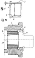
- Figures 3 to 8 and 10 to 14 show the roller in the installed position.
- Figures 1, 2 and 9 show the roller upside down to the installation position (reversed above and below).
- a roller for caterpillar tracks or the like endless belts or chains is shown. It consists of a roller body 1, an axis 2 passing through it, and bearings 3 and seals 4 arranged between the roller body 1 and the axle 4. End pieces 5 are fastened to the axially protruding ends of the roller body 1 and connected with spring pins 6, which are fixed to the frame are fixed to parts of the chassis or the like.
- Such a roller is shown in Figures 1, 3, 5, 8 and in principle also in Figures 11 and 12.
- FIG. 2 shows a roller which consists of a roller body 1 which has shaft ends 7 at its ends.
- the shaft ends 7 are rotatably mounted in end caps 8 which can be fixed to the frame, for which purpose corresponding bearings 3 and seals 4 are provided.
- the bearings arranged radially between the roller body 1 and the axle 2 or between the shaft ends 7 and end caps 8 are designed as spherical bearings, in particular as bearings with a spherical cross-sectional contour. Due to this design, they can follow deflections of the roller body 1 or the axis 2 caused by load without tilting.
- the bearings 3 can consist of a first bearing part 9 rotatably arranged on the axle 2 or the shaft stub 7 or formed integrally with this or this or non-rotatably arranged with respect to this or one in the roller body 1 or in the End caps 8 are rotatably or non-rotatably arranged second bearing part 10, the contact surface 11 between the first and second bearing parts 9, 10 being spherical in cross section.
- the central axis of the line of curvature of the crowned cross section crosses the longitudinal central axis 12 of the roller.
- Additional axial contact surfaces or bearings 13 can be formed for axially fixing the roller body 1 on the axis 2 or between the end caps 8.
- the roller body 1 can either rotate around the surface 14, so that the surface 11 is only used for pivoting. Or it can be rotated and pivoted in the area of the curved surface 11.
- the part 9 can also be formed in one piece with the axis 2.
- the axial loads can be absorbed by a correspondingly pronounced curved contour (at 11).
- FIG. 1 a to provide the first and the second bearing part 9, 10 only on one side with a corresponding rounding (crowned contour 11), this rounding on the side facing the other bearing 9, ends parallel to the central longitudinal axis of the roll. This can simplify assembly.
- a plain bearing bush is provided as the bearing 3 between the roller body 1 and the axle 2. This is conical or conical in the area of the highest load occurring when the roller body 1 or the axis 2 bends expanded, so that a corresponding gap 14 is established between the outwardly pointing end region of the plain bearing bush and the axis 2 in the load-free state.
- the force curve is indicated by the arrows F and the small arrows in the lower half of the drawing.
- the deflection line is shown at 15.
- the enlargement 15 is realized by a small radius R or by a small phase, for example an angular degree.
- the configuration is similar, the ends of the axes 2 being flattened there.
- the flattening is illustrated at 16. This makes it possible to insert the axle ends directly into a shape-matched, frame-side recess, the step 17 produced by the flattening 16 serving as a contact surface.
- the bearing bush of the bearing 3 is tapped in the region of the highest load, that is to say over a radius or a phase the sliding surface of the bushing of a bending line is adapted comparable to the bending line 15, a certain play is achieved, so that a deformation axis 2 is possible without extreme edge loads on the bearing. This relieves the most heavily loaded part. Due to the flattening 16, the previously used dowel pin 6 is omitted as an anti-rotation device and the end piece is structurally simplified. Through the contact surface 17 on the frame or frame, the misalignment of the axis 2 is minimized from tolerances.
- the roller body 1 mounted on the axle 2 consists of two partial bodies 18 which are arranged at an axial distance from one another.
- the axis 2 has a support 19 held fixed to the frame in the middle in the gap formed between the partial bodies 18.
- bearing elements 3 2 plain bearings are arranged between the partial bodies 18 and the axis.
- Both partial bodies 18 are provided at both axial ends with seals 4, which are arranged between the end faces of the partial bodies 18 and the end faces of the central support 19 or the end pieces 5.
- the load is divided by the three support points that are fixed to the frame.
- the short lever arms lead on the one hand to low deformations and on the other hand to small bending moments. The corresponding elements are therefore less stressed.
- a tubular metal bellows coupling (FIG. 13) or a tubular elastomer or rubber element is fastened between the partial bodies 18, so that the bending deformation caused by the load can be absorbed without damage.
- a separate partial roller 20 is arranged for each chain side (seen to the right and left of the running direction).
- the partial rollers on each chain side are arranged at a lateral distance from the partial rollers 20 on the other chain side.
- the partial rollers 20 on one side of the chain can either be aligned coaxially to the partial rollers on the other side of the chain, or they can also be offset axially parallel to one another in the running direction of the chain.
- the partial roller 20 has two wheel flanges 21.
- the bearings 3 have two stop surfaces 24 for absorbing the axial forces of the partial roller 20.
- the partial rollers 20 in turn consist of a roller body which is penetrated by an axis, the bearing 3 being arranged between the axis and the roller body.
- the partial roller bodies 20 each have only one running surface for one chain side.
- the rollers must therefore be arranged side by side (coaxially) or offset to each other in the direction of travel (axially parallel). Due to the short axis formation, deformations and bending moments are low. The burdens this reduces the number of axles, end pieces, screws and plain bearings.
- the axle consists in each case of stub axles 25 engaging in the end face of the roller body 1.
- the means for holding each stub axle 25 in a fixed frame are formed in one piece with the stub axle.
- the seat for the face seal 4 is mainly incorporated into the flange edge 26 between a flange collar 26 of the stub shaft 25 and the roller body.
- the bearing 3 between the stub shaft 25 and the roller body 1 is designed according to the embodiment according to FIG. 12 as a tapered bearing with a cone angle diverging towards the roller body end. Due to the relatively large stub axle 25, the screwing surface and the sealing seat 4 can be provided directly at the free end of the axle body. By dividing the axis, the overall system becomes softer and there is a certain degree of adjustment flexibility in the area of the bearings 4. The loads on the screw-on surface (mounting fixed to the frame) increase because the bending moment must also be supported. The screw-on surface directly at the end of the axle stub 25 means that fewer tolerances are superimposed, which reduces angular errors in the bearing.
- the end piece can be formed in one piece with the stub shaft, so that the Assembly effort is reduced. There is also no sealing between the axle and the end piece.
- the corresponding dowel pin is also omitted.
- the axle body can also be made of cast iron.
- the roller must be secured against falling apart when transported as an individual part in the assembled state.
- the rollers can in turn be attached to the frame by means of a central screw guided transversely to the roller axis.
- the load-bearing capacity of the rollers is increased and thus the service life is extended.
- the invention is not limited to the exemplary embodiments, but is often variable within the scope of the disclosure.
Landscapes
- Engineering & Computer Science (AREA)
- Mechanical Engineering (AREA)
- Chemical & Material Sciences (AREA)
- Combustion & Propulsion (AREA)
- Transportation (AREA)
- General Engineering & Computer Science (AREA)
- Rolls And Other Rotary Bodies (AREA)
- Rolling Contact Bearings (AREA)
- Rollers For Roller Conveyors For Transfer (AREA)
Applications Claiming Priority (2)
| Application Number | Priority Date | Filing Date | Title |
|---|---|---|---|
| DE19528837 | 1995-08-05 | ||
| DE19528837A DE19528837A1 (de) | 1995-08-05 | 1995-08-05 | Laufrolle für Raupenketten |
Publications (3)
| Publication Number | Publication Date |
|---|---|
| EP0759392A2 true EP0759392A2 (fr) | 1997-02-26 |
| EP0759392A3 EP0759392A3 (fr) | 1997-03-26 |
| EP0759392B1 EP0759392B1 (fr) | 2001-10-31 |
Family
ID=7768801
Family Applications (1)
| Application Number | Title | Priority Date | Filing Date |
|---|---|---|---|
| EP96112409A Expired - Lifetime EP0759392B1 (fr) | 1995-08-05 | 1996-08-01 | Galet pour chenilles |
Country Status (4)
| Country | Link |
|---|---|
| US (1) | US5803558A (fr) |
| EP (1) | EP0759392B1 (fr) |
| AT (1) | ATE207832T1 (fr) |
| DE (1) | DE19528837A1 (fr) |
Cited By (1)
| Publication number | Priority date | Publication date | Assignee | Title |
|---|---|---|---|---|
| EP2789528A1 (fr) * | 2013-04-12 | 2014-10-15 | Joseph Vögele AG | Agencement de galets pour chenille |
Families Citing this family (28)
| Publication number | Priority date | Publication date | Assignee | Title |
|---|---|---|---|---|
| IT1310498B1 (it) * | 1999-09-28 | 2002-02-18 | Italtractor | Rullo perfezionato per cingoli. |
| US6364438B1 (en) | 2000-04-20 | 2002-04-02 | Caterpillar Inc. | Press fit roller assemblies of an undercarriage assembly of a work machine and method of making the same |
| US6457786B1 (en) | 2000-04-20 | 2002-10-01 | Caterpillar Inc. | Roller assembly of an undercarriage assembly having an integrated retainer and thrust bushing and method for making the same |
| US6474754B1 (en) * | 2000-08-24 | 2002-11-05 | Caterpillar Inc | Roller assembly for an undercarriage of a work machine |
| RU2243120C2 (ru) * | 2003-02-05 | 2004-12-27 | Открытое акционерное общество "ВЭКС" | Опорный каток |
| JP4288564B2 (ja) * | 2003-03-14 | 2009-07-01 | 株式会社小松製作所 | 転輪用シャフト |
| US7374257B2 (en) * | 2005-02-11 | 2008-05-20 | Caterpillar Inc. | Machine track roller assembly |
| DE102006042551A1 (de) * | 2006-09-11 | 2008-04-10 | Freiberger Lebensmittel Gmbh & Co. Produktions- Und Vertriebs Kg | Gleitlager für hohe Betriebstemperaturen |
| CN101939210B (zh) * | 2008-02-13 | 2012-11-28 | 株式会社小松制作所 | 履带式行驶装置及滚轮组装体 |
| JP5398350B2 (ja) * | 2009-05-21 | 2014-01-29 | 株式会社小松製作所 | 履帯式走行車両の転輪 |
| JP2010274872A (ja) * | 2009-06-01 | 2010-12-09 | Komatsu Ltd | 履帯式走行車両の転輪 |
| US8231184B2 (en) * | 2009-11-24 | 2012-07-31 | Deere & Company | Crawler track roller with internal spherical spacers |
| USD727974S1 (en) | 2012-06-29 | 2015-04-28 | Caterpillar Inc. | Undercarriage track roller for mobile earthmoving machine |
| USD751609S1 (en) | 2012-06-29 | 2016-03-15 | Caterpillar Inc. | Undercarriage track link for mobile earthmoving machine |
| USD712935S1 (en) | 2012-06-29 | 2014-09-09 | Caterpillar Inc. | Undercarriage track shoe for mobile earthmoving machine |
| USD719588S1 (en) | 2012-06-29 | 2014-12-16 | Caterpillar Inc. | Undercarriage track system for mobile earthmoving machine |
| USD709527S1 (en) | 2012-06-29 | 2014-07-22 | Caterpillar Inc. | Undercarriage track idler for mobile earthmoving machine |
| CN104214207B (zh) * | 2014-09-01 | 2016-07-20 | 安徽省水利水电勘测设计院 | 特大型立式组合轴承装置 |
| US9694862B2 (en) * | 2015-02-25 | 2017-07-04 | Komatsu Ltd. | Work vehicle |
| US10300967B2 (en) | 2016-06-17 | 2019-05-28 | Srj, Inc. | Track and track roller |
| US10023251B2 (en) * | 2016-06-24 | 2018-07-17 | Caterpillar Inc. | Track roller assembly and method |
| IT201700007585A1 (it) * | 2017-01-24 | 2018-07-24 | Passini Holding S R L | Ruota per cingoli |
| US11554823B2 (en) * | 2019-09-09 | 2023-01-17 | Caterpillar Inc. | Sleeve bearing having a flared end |
| US12049266B2 (en) * | 2020-12-22 | 2024-07-30 | Caterpillar Inc. | Press fit roller collar |
| IT202100000725A1 (it) * | 2021-01-18 | 2022-07-18 | Berco Spa | Rullo per cingolo per guidare un cingolo di un veicolo cingolato, e sottocarro di un veicolo cingolato. |
| US20240158027A1 (en) * | 2022-11-14 | 2024-05-16 | Soucy International Inc. | Wheel assembly, track system, and light-heavy duty vehicle |
| CN116443128B (zh) * | 2022-12-16 | 2025-12-16 | 福建省泉州市诚法电气机械科技有限公司 | 支重轮、侧盖、轮体及其密封、微调、加油装置以及安装、拆卸工具和方法 |
| US20250162663A1 (en) * | 2023-11-17 | 2025-05-22 | L&H Industrial, Inc. | Mounting and sealing assembly |
Family Cites Families (16)
| Publication number | Priority date | Publication date | Assignee | Title |
|---|---|---|---|---|
| DE331467C (de) * | 1916-11-25 | 1921-01-07 | Atlas Maschb G M B H | Motorfahrzeug mit Laufketten |
| DE1750294A1 (de) * | 1967-05-20 | 1971-01-14 | Massey Ferguson Services Nv | Dichtung fuer Lager |
| DE6924259U (de) * | 1969-06-16 | 1969-10-30 | Tractortecnic Gebr Kulenkampff | Laufrolle fuer raupenfahrzeuge |
| US3578822A (en) * | 1969-08-12 | 1971-05-18 | Fmc Corp | Dynamically balanced power transmission |
| US3869931A (en) * | 1973-12-12 | 1975-03-11 | Caterpillar Tractor Co | Track roller with replaceable and reversible flanges |
| US3929385A (en) * | 1974-10-03 | 1975-12-30 | Us Army | Vehicle track support |
| US3945693A (en) * | 1975-04-25 | 1976-03-23 | Caterpillar Tractor Co. | Track roller |
| US3980149A (en) * | 1975-05-12 | 1976-09-14 | Caterpillar Tractor Co. | Stress-relieved axle mounting for track-type vehicles |
| US4152031A (en) * | 1977-08-25 | 1979-05-01 | Caterpillar Tractor Co. | Track roller with oil filter |
| US4209205A (en) * | 1977-12-20 | 1980-06-24 | Caterpillar Tractor Co. | Inspection of track assemblies |
| US4371362A (en) * | 1980-04-02 | 1983-02-01 | Dorris F Hoyt | Track roller system |
| US4772151A (en) * | 1987-12-21 | 1988-09-20 | Caterpillar Inc. | Pivot assembly |
| DE8900576U1 (de) * | 1989-01-20 | 1989-03-23 | Abg-Werke Gmbh, 3250 Hameln | Kettenlaufwerk für Kettenfahrzeuge |
| DD299110A7 (de) * | 1990-08-23 | 1992-04-02 | Planeta Druckmaschinenwerk Ag,De | Stuetzring fuer druckzylinder an rotationsdruckmaschinen |
| JPH06146771A (ja) * | 1992-11-11 | 1994-05-27 | Nippon Steel Corp | 立坑の構築方法 |
| US5553931A (en) * | 1994-12-15 | 1996-09-10 | Caterpillar Inc. | Track roller assembly |
-
1995
- 1995-08-05 DE DE19528837A patent/DE19528837A1/de not_active Withdrawn
-
1996
- 1996-07-31 US US08/688,184 patent/US5803558A/en not_active Expired - Fee Related
- 1996-08-01 AT AT96112409T patent/ATE207832T1/de not_active IP Right Cessation
- 1996-08-01 EP EP96112409A patent/EP0759392B1/fr not_active Expired - Lifetime
Cited By (2)
| Publication number | Priority date | Publication date | Assignee | Title |
|---|---|---|---|---|
| EP2789528A1 (fr) * | 2013-04-12 | 2014-10-15 | Joseph Vögele AG | Agencement de galets pour chenille |
| US9708019B2 (en) | 2013-04-12 | 2017-07-18 | Joseph Voegele Ag | Track-supporting roller assembly for a crawler chassis |
Also Published As
| Publication number | Publication date |
|---|---|
| ATE207832T1 (de) | 2001-11-15 |
| EP0759392B1 (fr) | 2001-10-31 |
| EP0759392A3 (fr) | 1997-03-26 |
| US5803558A (en) | 1998-09-08 |
| DE19528837A1 (de) | 1997-02-06 |
Similar Documents
| Publication | Publication Date | Title |
|---|---|---|
| EP0759392A2 (fr) | Galet pour chenilles | |
| DE2656799C2 (de) | Verfahren zum Herstellen eines elastisch nachgiebigen Bauteiles sowie Verwendung der verfahrensgemäß hergestellten Bauteils als elastisches Schwenklager für einen Querlenker einer Fahrzeugachse | |
| EP3284975B1 (fr) | Axe planetaire | |
| EP1463891A1 (fr) | Joint a rotule | |
| DE19852446B4 (de) | Befestigungsanordnung für ein Lenkgetriebegehäuse | |
| DE3441560C2 (fr) | ||
| DE10164598B4 (de) | Anschlussvorrichtung zum Anschließen von Anschlag- oder Verzurrmitteln | |
| EP1604124B1 (fr) | Articulation | |
| EP1745219B1 (fr) | Douille et liaison articulee comprenant une douille de ce type | |
| DE19517441C1 (de) | Gelenkbeschlag für Sitze mit verstellbarer Rückenlehne, insbesondere Kraftfahrzeugsitze | |
| DE69203933T2 (de) | Lagerbüchse und Befestigungsschelle für Universalgelenk. | |
| EP1002674B1 (fr) | Liaison entre les extrémités d'un ressort à lames et les supports d'essieu d'un ensemble d'essieux en tandem pour véhicules utilitaires | |
| EP1565370A1 (fr) | Palier pivotant et essieu orientable muni d'un tel palier | |
| DE102015109546B3 (de) | Gelenkgabel für ein Kreuzgelenk und Kreuzgelenk | |
| EP1978275A2 (fr) | Articulation, en particulier sur une plateforme pivotante entre un wagon avant et un wagon arrière d'un bus à plateforme pivotante | |
| DE69814615T2 (de) | Rollen- oder Hülsentreibkette mit zwei Kettengliederreihen mit versetzten Gelenkbolzen | |
| WO1999047438A1 (fr) | Chaine articulee | |
| DE3308499C2 (de) | Bremszange für eine Scheibenbremse | |
| EP1124076B1 (fr) | Palier de pivotement, en particulier palier pour une barre stabilisatrice d' un véhicule | |
| DE102012017892A1 (de) | Drehstützlager | |
| DE20212294U1 (de) | Lenkwelle für Kraftfahrzeuge | |
| DE29512636U1 (de) | Laufrolle für Raupenketten | |
| DE10229753B4 (de) | Für einen Achslenker eines Kraftfahrzeuges ausgebildetes Gelenklager | |
| EP1008781A2 (fr) | Palier à articulation, en particulier palier d'oeillet de ressort | |
| DE4141520C1 (fr) |
Legal Events
| Date | Code | Title | Description |
|---|---|---|---|
| PUAI | Public reference made under article 153(3) epc to a published international application that has entered the european phase |
Free format text: ORIGINAL CODE: 0009012 |
|
| PUAL | Search report despatched |
Free format text: ORIGINAL CODE: 0009013 |
|
| AK | Designated contracting states |
Kind code of ref document: A2 Designated state(s): AT BE FR GB IT SE |
|
| AK | Designated contracting states |
Kind code of ref document: A3 Designated state(s): AT BE FR GB IT SE |
|
| 17P | Request for examination filed |
Effective date: 19970408 |
|
| 17Q | First examination report despatched |
Effective date: 19981014 |
|
| GRAG | Despatch of communication of intention to grant |
Free format text: ORIGINAL CODE: EPIDOS AGRA |
|
| GRAG | Despatch of communication of intention to grant |
Free format text: ORIGINAL CODE: EPIDOS AGRA |
|
| GRAH | Despatch of communication of intention to grant a patent |
Free format text: ORIGINAL CODE: EPIDOS IGRA |
|
| GRAH | Despatch of communication of intention to grant a patent |
Free format text: ORIGINAL CODE: EPIDOS IGRA |
|
| GRAA | (expected) grant |
Free format text: ORIGINAL CODE: 0009210 |
|
| RAP1 | Party data changed (applicant data changed or rights of an application transferred) |
Owner name: IAMT INGENIEURGESELLSCHAFT FUER ALLGEMEINE MASCHI Owner name: INTERTRACTOR GMBH |
|
| AK | Designated contracting states |
Kind code of ref document: B1 Designated state(s): AT BE FR GB IT SE |
|
| PG25 | Lapsed in a contracting state [announced via postgrant information from national office to epo] |
Ref country code: IT Free format text: LAPSE BECAUSE OF FAILURE TO SUBMIT A TRANSLATION OF THE DESCRIPTION OR TO PAY THE FEE WITHIN THE PRESCRIBED TIME-LIMIT;WARNING: LAPSES OF ITALIAN PATENTS WITH EFFECTIVE DATE BEFORE 2007 MAY HAVE OCCURRED AT ANY TIME BEFORE 2007. THE CORRECT EFFECTIVE DATE MAY BE DIFFERENT FROM THE ONE RECORDED. Effective date: 20011031 Ref country code: GB Free format text: LAPSE BECAUSE OF FAILURE TO SUBMIT A TRANSLATION OF THE DESCRIPTION OR TO PAY THE FEE WITHIN THE PRESCRIBED TIME-LIMIT Effective date: 20011031 |
|
| REF | Corresponds to: |
Ref document number: 207832 Country of ref document: AT Date of ref document: 20011115 Kind code of ref document: T |
|
| PG25 | Lapsed in a contracting state [announced via postgrant information from national office to epo] |
Ref country code: SE Free format text: LAPSE BECAUSE OF FAILURE TO SUBMIT A TRANSLATION OF THE DESCRIPTION OR TO PAY THE FEE WITHIN THE PRESCRIBED TIME-LIMIT Effective date: 20020131 |
|
| GBV | Gb: ep patent (uk) treated as always having been void in accordance with gb section 77(7)/1977 [no translation filed] |
Effective date: 20011031 |
|
| PG25 | Lapsed in a contracting state [announced via postgrant information from national office to epo] |
Ref country code: AT Free format text: LAPSE BECAUSE OF NON-PAYMENT OF DUE FEES Effective date: 20020801 |
|
| PG25 | Lapsed in a contracting state [announced via postgrant information from national office to epo] |
Ref country code: BE Free format text: LAPSE BECAUSE OF NON-PAYMENT OF DUE FEES Effective date: 20020831 |
|
| PLBE | No opposition filed within time limit |
Free format text: ORIGINAL CODE: 0009261 |
|
| STAA | Information on the status of an ep patent application or granted ep patent |
Free format text: STATUS: NO OPPOSITION FILED WITHIN TIME LIMIT |
|
| 26N | No opposition filed | ||
| BERE | Be: lapsed |
Owner name: *IAMT INGENIEURG.- FUR ALLGEMEINE MASCHINENTECHNIK Effective date: 20020831 Owner name: *INTERTRACTOR G.M.B.H. Effective date: 20020831 |
|
| PGFP | Annual fee paid to national office [announced via postgrant information from national office to epo] |
Ref country code: FR Payment date: 20080731 Year of fee payment: 13 |
|
| REG | Reference to a national code |
Ref country code: FR Ref legal event code: ST Effective date: 20100430 |
|
| PG25 | Lapsed in a contracting state [announced via postgrant information from national office to epo] |
Ref country code: FR Free format text: LAPSE BECAUSE OF NON-PAYMENT OF DUE FEES Effective date: 20090831 |