EP3284975B1 - Axe planetaire - Google Patents
Axe planetaire Download PDFInfo
- Publication number
- EP3284975B1 EP3284975B1 EP16184864.3A EP16184864A EP3284975B1 EP 3284975 B1 EP3284975 B1 EP 3284975B1 EP 16184864 A EP16184864 A EP 16184864A EP 3284975 B1 EP3284975 B1 EP 3284975B1
- Authority
- EP
- European Patent Office
- Prior art keywords
- planetary
- axis
- area
- axle
- handlebar
- Prior art date
- Legal status (The legal status is an assumption and is not a legal conclusion. Google has not performed a legal analysis and makes no representation as to the accuracy of the status listed.)
- Active
Links
Images


Classifications
-
- F—MECHANICAL ENGINEERING; LIGHTING; HEATING; WEAPONS; BLASTING
- F16—ENGINEERING ELEMENTS AND UNITS; GENERAL MEASURES FOR PRODUCING AND MAINTAINING EFFECTIVE FUNCTIONING OF MACHINES OR INSTALLATIONS; THERMAL INSULATION IN GENERAL
- F16H—GEARING
- F16H57/00—General details of gearing
- F16H57/08—General details of gearing of gearings with members having orbital motion
-
- F—MECHANICAL ENGINEERING; LIGHTING; HEATING; WEAPONS; BLASTING
- F16—ENGINEERING ELEMENTS AND UNITS; GENERAL MEASURES FOR PRODUCING AND MAINTAINING EFFECTIVE FUNCTIONING OF MACHINES OR INSTALLATIONS; THERMAL INSULATION IN GENERAL
- F16H—GEARING
- F16H57/00—General details of gearing
- F16H57/08—General details of gearing of gearings with members having orbital motion
- F16H57/082—Planet carriers
-
- F—MECHANICAL ENGINEERING; LIGHTING; HEATING; WEAPONS; BLASTING
- F16—ENGINEERING ELEMENTS AND UNITS; GENERAL MEASURES FOR PRODUCING AND MAINTAINING EFFECTIVE FUNCTIONING OF MACHINES OR INSTALLATIONS; THERMAL INSULATION IN GENERAL
- F16H—GEARING
- F16H1/00—Toothed gearings for conveying rotary motion
- F16H1/28—Toothed gearings for conveying rotary motion with gears having orbital motion
- F16H1/2809—Toothed gearings for conveying rotary motion with gears having orbital motion with means for equalising the distribution of load on the planet gears
- F16H1/2836—Toothed gearings for conveying rotary motion with gears having orbital motion with means for equalising the distribution of load on the planet gears by allowing limited movement of the planet gears relative to the planet carrier or by using free floating planet gears
-
- F—MECHANICAL ENGINEERING; LIGHTING; HEATING; WEAPONS; BLASTING
- F16—ENGINEERING ELEMENTS AND UNITS; GENERAL MEASURES FOR PRODUCING AND MAINTAINING EFFECTIVE FUNCTIONING OF MACHINES OR INSTALLATIONS; THERMAL INSULATION IN GENERAL
- F16H—GEARING
- F16H37/00—Combinations of mechanical gearings, not provided for in groups F16H1/00 - F16H35/00
- F16H37/12—Gearings comprising primarily toothed or friction gearing, links or levers, and cams, or members of at least two of these types
-
- F—MECHANICAL ENGINEERING; LIGHTING; HEATING; WEAPONS; BLASTING
- F16—ENGINEERING ELEMENTS AND UNITS; GENERAL MEASURES FOR PRODUCING AND MAINTAINING EFFECTIVE FUNCTIONING OF MACHINES OR INSTALLATIONS; THERMAL INSULATION IN GENERAL
- F16H—GEARING
- F16H57/00—General details of gearing
- F16H57/02—Gearboxes; Mounting gearing therein
- F16H57/021—Shaft support structures, e.g. partition walls, bearing eyes, casing walls or covers with bearings
-
- F—MECHANICAL ENGINEERING; LIGHTING; HEATING; WEAPONS; BLASTING
- F16—ENGINEERING ELEMENTS AND UNITS; GENERAL MEASURES FOR PRODUCING AND MAINTAINING EFFECTIVE FUNCTIONING OF MACHINES OR INSTALLATIONS; THERMAL INSULATION IN GENERAL
- F16H—GEARING
- F16H57/00—General details of gearing
- F16H57/02—Gearboxes; Mounting gearing therein
- F16H57/023—Mounting or installation of gears or shafts in the gearboxes, e.g. methods or means for assembly
-
- F—MECHANICAL ENGINEERING; LIGHTING; HEATING; WEAPONS; BLASTING
- F16—ENGINEERING ELEMENTS AND UNITS; GENERAL MEASURES FOR PRODUCING AND MAINTAINING EFFECTIVE FUNCTIONING OF MACHINES OR INSTALLATIONS; THERMAL INSULATION IN GENERAL
- F16H—GEARING
- F16H57/00—General details of gearing
- F16H57/08—General details of gearing of gearings with members having orbital motion
- F16H2057/085—Bearings for orbital gears
Definitions
- the present invention relates to a planetary axis and a planetary gear stage.
- planetary gears planet gears rotatably mounted on planet axes mesh simultaneously with an internally toothed ring gear and with an externally toothed sun wheel. It is known to make modifications to improve the elasticity of the planetary axes in order to be able to compensate for design and load-related misalignments of the planetary gears relative to the ring gear and the sun gear.
- EP 2 559 915 A1 (General Electric Company) 02/20/2013 shows in Fig. 4 a planetary pin ("pin") 50, which in the area of its two ends each has a borehole ("bore hole”) 94 running transversely to the longitudinal axis.
- pin planetary pin
- Bore hole borehole
- the object of the present invention is to provide an improved planetary axis. This object is achieved by a planetary axis with the features specified in claims 1 and 2.
- the invention is based on the knowledge that the planet gear bearing on the planet axis of a planetary gear is comparable to a wheel suspension in an automobile, the chassis of the planet axis and the road corresponding to the planet carrier.
- the chassis is said to be even on an uneven one Avoid changing its position if possible.
- the planet axis of a planetary gear should also not change its position to the ring gear and the sun.
- the solution according to the invention therefore consists in that known wheel suspensions in the automotive sector are transferred to the planetary axis.
- the following variants of the wheel suspension have proven suitable for an analog application: wishbone axle, thrust / flexible link axle and trailing link axle.
- the planetary axis is stressed relatively little in comparison to other machine elements of the planetary gear, so that geometric modifications can be made to the planetary axis without exceeding the limits of the load-bearing capacity.
- different elastic-acting path-balancing mechanisms are used, which lead to a soft planetary gear suspension.
- a double wishbone wheel suspension in the automotive sector, two links mounted on the frame (so-called wishbone arms or wishbone arms) swing transversely to the direction of travel (double swing arm).
- the frame corresponds to the planet carrier.
- the wishbones are not articulated on the planetary axis, but are rigid; in this case they take over the spring function at the same time, which otherwise takes over a separate spring damper element.
- the handlebars connect the clamping area and the bearing seat area of the planetary axle. By varying the handlebar lengths and cross-sections, the rigidity and thus the type of steering of the system can be varied.
- the planetary axis has a variable shear stiffness via the through openings running transversely to the longitudinal axis.
- the handlebar axis generates relative displacements of bearing seat areas through handlebar elements.
- the single push / flex joint also compensates for differences in stiffness in the circumferential direction.
- the inventive The solution is characterized in that the planetary axis is at least unlatched on one side between the clamping areas in such a way that a thrust / bending link is created.
- the deflection can be controlled by a clever choice of cross section and length of the generated profile.
- This variant has advantages if there is a strong misalignment of the planetary axis bores due to a deformation of the planet carrier cheeks. However, this variant creates a bending moment in the axis mount.
- the transmission of the trailing arm axle mechanism known from the automotive field to the planetary suspension is characterized in that the center of gravity of the link region is eccentric to the center of gravity of the bearing seat area and / or to the center of gravity of the support / clamping area.
- the planet can carry out circular orbital movements around the center of gravity of the eccentric body, the radius of the circular path corresponding to the distance between the center of gravity of the two bodies.
- the planetary axle is designed analogously to a wishbone axle and, between a clamping area for clamping in a planet carrier cheek and a bearing seat area for receiving a planetary bearing, has a handlebar area with at least one through opening running transverse to the planetary axis and at least two wishbone arms connecting the clamping area and the bearing seat area.
- the planetary axis is designed analogously to a thrust / flexible link axis and has a handlebar region with a bar between a clamping area for clamping in a planet carrier cheek and a bearing seat area for receiving a planetary bearing.
- the planetary axle is designed analogously to a trailing arm axle and has a handlebar area between a clamping area for clamping in a planet carrier cheek and a bearing seat area for receiving a planetary bearing, the center of gravity of the handlebar area being formed eccentrically to the center axis of the bearing seat area and / or the center axis of the clamping area is.
- the object is achieved by a planetary gear stage with a planetary axis according to the invention.
- the through opening is oriented perpendicular to an orbit of the planetary axis.
- the plane of the beam runs radially to a sun gear of the planetary gear stage.
- the center of gravity of the link region is formed eccentrically radially to a sun gear of the planetary gear stage.
- the wishbones can have different lengths and cross sections. The advantage here is that the spring stiffness of the wishbones can be adjusted.
- the transition of the handlebars to the neighboring areas can be provided with radii or elliptical fillets. The advantage here is that no voltage peaks occur or voltage peaks are reduced.
- the axis is designed in such a way that the axis itself generates / translates and / or rotates displacements of the partial regions relative to one another under load.
- the advantage here is that the desired deflections of the axis can be set to compensate for axis restriction and axis inclination errors.
- a spacer sleeve with the highest possible rigidity is interposed to widen the bearing seat area between the bearing seat of the axle and the bearings (roller or slide bearings).
- the advantage here is that longer wishbone arms are possible with the same installation space in relation to conventional designs. An increased deflection can thus be achieved.
- a high degree of rigidity ensures that the force is distributed evenly across the width of the bearing.
- the axis consists of one or more arbitrary uniform profiles.
- the advantage here is that they are easy to manufacture.
- the handlebar mechanism is fabricated and / or positively and / or non-positively.
- the advantage here is that the handlebar mechanism can be composed of bodies made of different different materials. Furthermore, a handlebar mechanism made of several elements is advantageous for assembly.
- the axis has at least one jump in the shear stiffness profile transverse to the axis. It is a property of the axis. The advantage is that you can achieve higher deformations compared to axles with constant shear rigidity in a small installation space. The reason for this is that there is shear and bending stiffness superimpose and in the case of short bodies the shear stiffness is dominant over the bending stiffness.
- the outer dimensions (diameter) of the handlebar area are smaller than those of the clamping area or bearing seat area.
- the advantage here is that sleeves without heels can be used.
- the stiffness and deformation properties of the axle can be adjusted by varying the length and height of the handlebars (handlebar profiles) and their position over the height of the axle.
- the advantage here is that, on the one hand, the nesting of the axis into the planetary axis bore and, on the other hand, the inclination of the axis relative to the planet carrier can be adjusted. In the automobile, the camber is stopped.
- the planetary axis is designed as a simple thrust / bending link.
- the advantage here is that the axis between the clamping area and the bearing seat enables elastic translatory and rotary deflections.
- the planetary axis is designed as a multiple thrust / bending link.
- the advantage here is that at least two directional stiffness properties can be formed between the clamping point and the bearing seat and thus axis inclination and axis restriction errors can be compensated for.
- the axle is supported / clamped on one side, on both sides or in the center.
- the advantage here is that the axle can be used in a planet carrier with one cheek, in a conventional one with two cheeks or one with a central cheek, similar to a bogie plate.
- the axis is positively and / or non-positively secured against rotation in the planet carrier.
- the advantage here is that this avoids twisting or axial movement of the axis in the planet carrier.
- the axis of the bearing seat is arranged eccentrically to the axis of gravity of the eccentric profile.
- the advantage here is that the bearing seat can perform an elastic pivoting movement with respect to the clamping point about the axis of gravity of the eccentric region.
- the axis has tapered areas.
- conical press seats can also be realized with conical counterparts.
- the center of gravity of the link region is formed eccentrically to the central axis of the planetary axis, wherein a plane spanned by the centerline and central axis can be oriented as desired, preferably tangentially or perpendicular to the circular path of the planet.
- the predominantly creative solution consists at least of a support / clamping area 1 for supporting or clamping the planetary axis in a planet carrier, a handlebar area 2 with a defined axial length 200 and a bearing seat area 3 with a bearing seat for mounting / receiving the bearing.
- the handlebar region 2 has at least one through-opening 12 with any cross-section transverse to the central axis R.
- the material of the planetary axis 100 which remains in the handlebar region 2 after the through-opening 12 has been produced, forms at least two wishbone arms 7, 8, which connect the regions 1 and 3 ,
- the control arm 7, 8 can have any cross section 9, 10. Due to the unequal design of the handlebar lengths, a defined inclination of the axes of area 1 to area 3 can be generated or superimposed for parallel displacement.
- the transition of the links 7, 8 to the neighboring areas is preferably provided with radii or elliptical fillets 11.
- the diameter of the handlebar area 2 can be smaller than the diameter of the clamping area 1 or the bearing seat area 3. This is necessary so that the handlebars 7, 8 do not collide with an optional spacer sleeve when deflecting.
- the axis for the storage of gear wheels has a clamping area 1, 5, a central area 3 with the bearing seat, and in each case between clamping area 1, 5 and bearing seat 3, a wishbone area 2 for fixing in a double-walled frame, that is, the double-walled planet carrier 4.
- the wishbones 7, 8, 14, 15 result from the introduction of two through openings 12, 13 lying transversely to the central axis R.
- the wishbones 7, 8, 14, 15 permit an elastic parallel displacement of the central area 3 to the two clamping areas 1, 5.
- the deflection of the axle areas 1, 3, 5 can be adjusted by varying the handlebar cross sections 9, 10.
- the links 7, 8, 14, 15 can have different cross sections and lengths.
- the transition of the links 7, 8, 14, 15 to the neighboring areas 1, 3, 5 is preferably provided with radii or elliptical fillets 11.
- the diameter of the handlebar area 2, 4 can be made smaller than that of the clamping areas 1, 5 or the bearing seat area 3. This is necessary so that the handlebars 7, 8, 14, 15 do not collide with an optional spacer sleeve when deflecting.
- Fig. 7 shows a perspective view of a two-sided clamped axle with a double wishbone mechanism with differently designed links 7, 8, 14, 15.
- Fig. 8 shows a first embodiment of a planetary gear plain bearing with double wishbone and spacer sleeve 17.
- a planetary axis 100 is clamped with its clamping areas 1, 5 located at the ends of the planetary axis 100 in two planet carrier cheeks 16.
- the area of the planetary axle 100 which is exposed in between is divided into an axially central bearing seat area 3 and two handlebar areas 2, 4 each lying between the bearing seat area 3 and the clamping areas 1, 5.
- the handlebar areas 2, 4 each have a through opening 12 running transversely to the planetary axis , 13 on.
- the two through openings 12, 13 have different cross sections, so that the links 7, 8, 14, 15 at both through openings 12, 13, ie the webs of the planetary axis 100 remaining in the handlebar areas 2, 4, are also of different widths.
- the section AA is in Fig. 6 shown.
- a spacer sleeve 17 sits on the planet axis 100 between the planet carrier cheeks 16, which in turn is surrounded by a slide bearing sleeve 19 and a planet gear 20.
- the spacer sleeve 17 has an undercut 18 on its inner diameter at each end, so that the spacer sleeve 17 does not touch the planetary axis 100 in the handlebar areas 2, 4.
- the spacer sleeve 17 touches the planet axis 100 only in the central bearing seat area 3, while in the adjacent handlebar areas 2, 4 the spacer sleeve 17 is radially spaced from the planet axis 100.
- the radial spacing in the area of the handlebar areas 2, 4 serves to allow the planetary axis 100 to be radially displaced or deformed in the handlebar areas 2, 4.
- Fig. 9 shows an embodiment of a planetary gear plain bearing with double wishbone and without spacer sleeve.
- execution shown largely corresponds to that in Fig. 8 shown embodiment, with the difference that the in Fig. 9 shown embodiment is carried out without a spacer sleeve 17.
- the slide bearing sleeve 19 is seated directly on the planetary axis 100, although - analogously to that in FIG Fig. 8 Shown embodiment - the slide bearing sleeve 19 has an undercut 18 at its inner diameter at each end, so that the slide bearing sleeve 19 does not touch the planetary axis 100 in the handlebar areas 2, 4.
- Fig. 9 shows an embodiment of a planetary gear plain bearing with double wishbone and without spacer sleeve.
- FIG. 10 shows an embodiment of a planetary gear roller bearing with double wishbone and spacer sleeve.
- execution shown largely corresponds to that in Fig. 8 shown embodiment, with the difference that the in Fig. 10 shown embodiment has a bearing inner ring 22 and roller bearing 21 instead of the plain bearing sleeve 19.
- Fig. 11 shows an embodiment of a planetary gear roller bearing with double wishbone and without spacer sleeve.
- execution shown largely corresponds to that in Fig. 10 shown embodiment, with the difference that the in Fig. 11 shown embodiment is carried out without a spacer sleeve 17.
- the bearing inner rings 22 sit directly on the planet axis 100, but the bearing inner rings 22 and the rolling bearings surrounding the bearing inner rings 22 21 are arranged exclusively in the central bearing seat area 3.
- the radial displacement or deformation of the planetary axis 100 in the handlebar areas 2, 4 is negligible compared to the resulting space between the planetary axis 100 and the planetary gear 20.
- Fig. 12 shows schematically the deflection of the planetary axis 100, which is reflected in a change in position ⁇ of the bearing seat region 3 of the planetary axis 100, under load F in the case of coaxial supports 23, 24.
- the planetary axis system in this case deflects itself symmetrically.
- the roller bearing seat 3 deflects horizontally by the path difference ⁇ .
- Fig. 13 shows in simplified form the deflection of the planetary axis 100 in the case of eccentrically positioned supports 23, 24, for example in the case of a twisted planet carrier.
- the soft transverse bending links 7, 8, 14, 15 can compensate for the relative displacement e in the support 24, the bearing seat 3 also remains horizontal. This applies in the event that the clamping areas 1, 5 of the planetary axis 100 are clamped rigidly. Depending on the bending / shear stiffness of the handlebars, different reaction forces arise in the clamping. If the clamping areas 1, 5 are not clamped rigidly, the bending / shear stiffness of the right link 14, 15 to that of the left link 7, 8 must be set to the desired translational deflection. The reaction force in the clamping points 1, 5 is almost the same in this case.
- the planetary axis 100 has at a first end a first region 1 for support / clamping in the planet carrier, followed by a first thrust / bending link 25, then a bearing seat region 3 for receiving the gearwheel with the associated bearing mechanism, followed by a second thrust / Flexure 26 and then at another end a second area 5 for support / clamping in the planet carrier.
- the relative rotation of the two planet carrier cheeks relative to one another also results in a relative rotation of the two opposite planetary axis bores. This relative rotation of the axle receptacles can thus be elastically compensated for by the planetary axle 100, and micro-slip between the axle and the planetary axle bore can thus be avoided.
- the planetary axle 100 has at a first end a first area 1 for support / clamping in the planet carrier, followed by a first trailing arm area 2 with an eccentrically lying profile 27, then a bearing seat area 3 for receiving the gearwheel with the associated bearing mechanism, and then a second one Trailing arm area 4 with an eccentrically lying profile 28, and then at another end a second area 5 for support / clamping in the planet carrier.
- the axis of gravity 31 of the handlebar regions 27, 28 lies in the illustrated embodiment approximately in the region of the central axis of the eccentrically lying profiles 27, 28.
- the axis of gravity 32 of the clamping regions 1, 5 lies approximately in the Area of the center axis of the planetary axis 100, as well as the center of gravity 33 of the bearing seat area 3.
- An axis 100 for the storage of gears has for fixing in a double-walled frame, i.e. the planet carrier, at both ends a clamping area 1, 5, a central area 3 with the bearing seat and between the clamping area 1, 5 and the bearing seat area 3 a trailing arm area 2 and 4.
- the trailing arm axis is characterized in that the bearing seat area 3 and the clamping area 1, 5 are connected by a link area 2, 5 with any profile, the axis of gravity 31 of which is eccentric to the axis of gravity 33 of the bearing area 3.
- the bearing seat area 3 can now perform an elastic rotary movement about the center of gravity 31 of the handlebar areas 2, 4 on a circular path, the radius of which corresponds to the distance g of the center of gravity 31, 33.
- a planetary axis 100 is clamped with its clamping areas 1, 5 located at the ends of the planetary axis 100 in two planet carrier cheeks 16.
- the area of the planetary axle 100 which is exposed in between is divided into an axially central bearing seat area 3 and two handlebar areas 2, 4 each lying between the bearing seat area 3 and the clamping areas 1, 5.
- the handlebar areas 2, 4 each have a reference to the center of gravity 33 of the bearing seat area 3 eccentrically arranged profile 27, 28.
- the offset g indicates the distance between the center of gravity 33 of the bearing seat area 3 and the center of gravity 31 of the handlebar areas 2, 4.
- the section AA of the first profile 27 is in Fig. 24 shown.
- a spacer sleeve 17 is seated in the bearing seat area 3 between the planet carrier cheeks 16, which in turn is surrounded by inner bearing rings 22, roller bearings 21 and a planet gear 20.
- the spacer sleeve 17 has an undercut 18 at its inner diameter at each end, so that the spacer sleeve 17 does not touch the planetary axis 100, more precisely: the eccentric profiles 27, 28, in the handlebar areas 2, 4.
- the spacer sleeve 17 touches the planet axis 100 only in the central bearing seat area 3, while in the adjacent handlebar areas 2, 4 the spacer sleeve 17 is radially spaced from the planet axis 100.
- the radial spacing in the area of the handlebar areas 2, 4 serves to allow the planetary axis 100 to be radially displaced or deformed in the handlebar areas 2, 4.
- the trailing arm variant can also be designed without a spacer sleeve 17, alternatively with sliding bearings with and without a spacer sleeve 17.
- FIG. 25 and 26 each show a section through a further embodiment of a trailing arm profile 27, which is formed in the handlebar areas 2, 4 of a planetary axis. It is in Fig. 25 shown profile 27 is a trailing arm profile, whereas that in Fig. 26 Profile 27 shown is a double transverse trailing arm profile.
- Fig. 27 shows a section through an embodiment of a divided handlebar profile.
- a split construction for wishbones and for trailing arms with two single links is possible.
- the design largely follows the design according to Fig. 10 , but with the differences that the handlebar profiles in handlebar areas 2 and 4 according to Fig. 16 are formed and that the bearing seat area 3 with the bearing seat is interrupted by a free space 34, in other words: the planetary axis 100 consists of two halves which do not touch axially. This construction can also be seen as two separate planetary axles 100a, 100b with single links 2, 4.
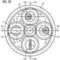
- Fig. 28 serves to illustrate an advantageous orientation of the profiles arranged in the handlebar area in relation to the overall system planetary gear stage.
- Fig. 28 shows a cross section through handlebar areas 2 of planetary axles 100a, 110b, 110c and 100d of a planetary gear stage with a fixed ring gear 35, a rotatably mounted sun gear 36, four rotatably mounted planet gears 20 with central axes R and a rotatably mounted planet carrier with a planet carrier cheek 38, in the viewing direction the central axis of rotation 37 of the planet carrier.
- the four planetary axles 100a, 100b, 100c, 100d, on which the planet gears 20 are rotatably mounted, are clamped into the planet carrier cheek 38 at right angles to them, distributed uniformly over the circumference.
- the teeth of the planet gears 20 mesh with the ring gear 35 surrounding the planet carrier 38.
- the sun gear 36 which also meshes with the planet gears 20, is arranged in the axial center 37 of the planet carrier.
- the sun gear is non-rotatably seated on a sun gear shaft 39 which is rotatably mounted about the axis of rotation 37.
- a first planetary axle 100a is configured analogously to a wishbone axle, with a cross section in the handlebar region as in FIG Fig. 6 shown.
- the through hole 12 extends perpendicular to the circular movement of the planetary axis 100a about the axis of rotation 37 of the planet carrier;
- the two wishbone arms 9, 10 of the handlebar region run parallel to a radial beam 40a, which begins at the axis of rotation 37 of the planet carrier and runs through the central axis R of the planetary axis 100a.
- a second planetary axis 100b is designed analogously to a push / flexure axis, with a cross section in the handlebar area as in Fig. 19 shown.
- the bar 25 of the handlebar region runs along a radial beam 40b, which begins at the axis of rotation 37 of the planet carrier and runs through the central axis R of the planetary axis 100b.
- a third planetary axle 100c is designed analogously to a trailing arm axle, with a cross section in the handlebar region as in FIG Fig. 22 shown.
- the axis of gravity 31 of the eccentrically arranged profile 27 is along a radial beam 40c, which begins at the axis of rotation 37 of the planet carrier and runs through the central axis R of the planetary axis 100c, offset by a distance g from the axis of gravity 33, in the direction of the beam.
- the axis of gravity 31 of the handlebar region 2 is thus formed eccentrically to the central axis R of the planetary axis 100 such that a plane spanned by the central axis 31 and the central axis R extends perpendicular to the circular path of the planet.
- a fourth planetary axle 100d is designed analogously to a trailing arm axle, with a cross section in the handlebar region as in FIG Fig. 22 shown.
- the center of gravity 31 of the eccentrically arranged profile 28 is transverse to a radial beam 40d, which begins at the axis of rotation 37 of the planet carrier and runs through the central axis R of the planetary axis 100d, by a distance g from the center of gravity 33, in the opposite direction a beam 40f which runs parallel to the radial beam 40c and through the central axis R of the planetary axis 100d.
- the axis of gravity 31 of the handlebar region 2 is thus designed eccentrically to the central axis R of the planetary axis 100 such that a plane spanned by the central axis 31 and the central axis R extends tangentially to the circular path of the planet.
Landscapes
- Engineering & Computer Science (AREA)
- General Engineering & Computer Science (AREA)
- Mechanical Engineering (AREA)
- Retarders (AREA)
Claims (5)
- Axe (100) planétaire d'un train planétaire, caractérisé en ce que l'axe (100) planétaire a, entre une partie (1) de blocage pour le blocage dans une roue d'une cage planétaire et une partie (3) de siège de palier pour la réception d'un palier planétaire, une partie (2) de bras, l'axe, passant par le centre de gravité, de la partie (2) de bras étant excentré par rapport à l'axe passant par le centre de gravité, de la partie (15) de siège de palier et/ou par rapport à l'axe, passant par le centre de gravité, de la partie (14) de blocage.
- Axe (100) planétaire d'un train planétaire, caractérisé en ce que l'axe (100) planétaire a, entre une partie (1) de blocage pour le blocage dans une joue de porte-satellite planétaire et une partie (3) de siège de palier pour la réception d'un palier planétaire, une partie (2) de bras ayant au moins une ouverture (12) traversante s'étendant transversalement à l'axe planétaire et au moins deux traverses (7, 8) de bras reliant la partie (1) de blocage et la partie (3) de siège de palier.
- Etage de train planétaire ayant un axe (100) planétaire suivant l'une des revendications précédentes.
- Etage de train planétaire ayant un axe (100) planétaire suivant la revendication 2, dans lequel les ouvertures (12, 13) traversantes sont dirigées perpendiculairement à une piste de roulement de l'axe planétaire.
- Etage de train planétaire ayant un axe (100) planétaire suivant la revendication 1, dans lequel l'axe (31), passant par le centre de gravité, de la partie (2) de bras est excentré par rapport à l'axe (R) médian de l'axe (100) planétaire, un plan passant par l'axe (31), passant par l'axe de gravité, et par l'axe (R) médian pouvant être dirigé de manière quelconque, en étant de préférence tangent ou perpendiculaire à l'orbite du satellite.
Priority Applications (5)
| Application Number | Priority Date | Filing Date | Title |
|---|---|---|---|
| DK16184864.3T DK3284975T3 (da) | 2016-08-19 | 2016-08-19 | Planetaksel |
| ES16184864T ES2786572T3 (es) | 2016-08-19 | 2016-08-19 | Eje planetario |
| EP16184864.3A EP3284975B1 (fr) | 2016-08-19 | 2016-08-19 | Axe planetaire |
| CN201710707885.2A CN107763197B (zh) | 2016-08-19 | 2017-08-17 | 行星轮轴和行星齿轮箱级 |
| US15/680,913 US10371250B2 (en) | 2016-08-19 | 2017-08-18 | Planetary axle |
Applications Claiming Priority (1)
| Application Number | Priority Date | Filing Date | Title |
|---|---|---|---|
| EP16184864.3A EP3284975B1 (fr) | 2016-08-19 | 2016-08-19 | Axe planetaire |
Publications (2)
| Publication Number | Publication Date |
|---|---|
| EP3284975A1 EP3284975A1 (fr) | 2018-02-21 |
| EP3284975B1 true EP3284975B1 (fr) | 2020-02-26 |
Family
ID=56787305
Family Applications (1)
| Application Number | Title | Priority Date | Filing Date |
|---|---|---|---|
| EP16184864.3A Active EP3284975B1 (fr) | 2016-08-19 | 2016-08-19 | Axe planetaire |
Country Status (5)
| Country | Link |
|---|---|
| US (1) | US10371250B2 (fr) |
| EP (1) | EP3284975B1 (fr) |
| CN (1) | CN107763197B (fr) |
| DK (1) | DK3284975T3 (fr) |
| ES (1) | ES2786572T3 (fr) |
Families Citing this family (13)
| Publication number | Priority date | Publication date | Assignee | Title |
|---|---|---|---|---|
| FI3699461T3 (fi) * | 2019-02-19 | 2023-01-13 | Planeettavaihde | |
| FR3095252B1 (fr) * | 2019-04-19 | 2021-05-14 | Safran Trans Systems | Reducteur mecanique de turbomachine d’aeronef |
| US10935076B2 (en) * | 2019-05-03 | 2021-03-02 | Pratt & Whitney Canada Corp. | Journal bearing assembly with dual oil cavities |
| EP3770466B1 (fr) | 2019-07-25 | 2022-09-28 | Rolls-Royce Deutschland Ltd & Co KG | Boîte de vitesse planétaire |
| EP3795864A1 (fr) | 2019-09-20 | 2021-03-24 | Flender GmbH | Porte-satellites à amortissement de bruit optimisé, agencement de porte-satellites, engrenage planétaire, éolienne et application industrielle |
| US11209045B2 (en) * | 2020-02-14 | 2021-12-28 | Pratt & Whitney Canada Corp. | Dual land journal bearings for a compound planetary system |
| DE102020122430A1 (de) | 2020-08-27 | 2022-03-03 | Rolls-Royce Deutschland Ltd & Co Kg | Planetengetriebe |
| DE102021202882A1 (de) | 2021-03-24 | 2022-09-29 | Zf Friedrichshafen Ag | Planetengetriebe |
| DE102021205296B4 (de) | 2021-05-25 | 2023-02-02 | Zf Friedrichshafen Ag | Planetengetriebe |
| JP7641842B2 (ja) * | 2021-07-21 | 2025-03-07 | 株式会社マキタ | 電動工具 |
| DE102022104130A1 (de) | 2022-02-22 | 2023-08-24 | Renk Gmbh | Planetenträger für ein Getriebe |
| WO2024016324A1 (fr) * | 2022-07-22 | 2024-01-25 | 舍弗勒技术股份两合公司 | Multiplicateur planétaire et appareil à énergie éolienne |
| CN119467640A (zh) * | 2024-12-11 | 2025-02-18 | 上海智元新创技术有限公司 | 减速器、关节模组和机器人 |
Family Cites Families (21)
| Publication number | Priority date | Publication date | Assignee | Title |
|---|---|---|---|---|
| US2095794A (en) * | 1934-07-20 | 1937-10-12 | Reed Propeller Co Inc | Reduction gear |
| US3381548A (en) * | 1966-07-25 | 1968-05-07 | Wuelfel Eisenwerk | Planetary gearing |
| GB1508999A (en) * | 1974-05-29 | 1978-04-26 | Vickers Ltd | Gears |
| TWI368696B (en) * | 2008-11-27 | 2012-07-21 | Univ Nat Sun Yat Sen | Driving apparatus with intermission output movement |
| US8216108B2 (en) * | 2009-02-05 | 2012-07-10 | Friede & Goldman, Ltd. | Gear assembly with tapered flex pin |
| EP2366988A1 (fr) | 2010-03-19 | 2011-09-21 | Winergy AG | Procédé et dispositif de détection de couple dans un engrenage au moyen d'un capteur de vibrations |
| ES2393850T3 (es) | 2010-04-30 | 2012-12-28 | Winergy Ag | Engranaje planetario (epicicloidal) para un aerogenerador |
| EP2508754B1 (fr) | 2011-04-04 | 2016-03-30 | Siemens Aktiengesellschaft | Système de transmission pour une éolienne |
| US8777802B2 (en) * | 2011-04-29 | 2014-07-15 | General Electric Company | Gear system and method for using same |
| DE102011075906A1 (de) * | 2011-05-16 | 2012-11-22 | Zf Friedrichshafen Ag | Flexibler Planetenbolzen |
| EP2541096A1 (fr) | 2011-06-30 | 2013-01-02 | Siemens Aktiengesellschaft | Système de propulsion pour une éolienne |
| EP2541058B1 (fr) | 2011-06-30 | 2014-04-30 | Siemens Aktiengesellschaft | Système de propulsion pour une éolienne |
| EP2549257B1 (fr) | 2011-07-18 | 2013-10-30 | Siemens Aktiengesellschaft | Procédé de détection de dommages sur des engrenages |
| US8550955B2 (en) | 2011-08-16 | 2013-10-08 | General Electric Company | Pin for planetary gear system |
| US8506446B2 (en) * | 2011-08-16 | 2013-08-13 | General Electric Company | Pin for planetary gear system |
| DK2573386T3 (en) | 2011-09-26 | 2015-02-09 | Siemens Ag | Drive system for a wind power plant |
| EP2674581A1 (fr) | 2012-06-15 | 2013-12-18 | Siemens Aktiengesellschaft | Composants de machine d'une chaîne cinématique ainsi que la méthode de conception et/ou de mettre en service et/ou d'opération d'une telle chaîne cinématique |
| ES2715997T3 (es) | 2012-09-17 | 2019-06-07 | Flender Gmbh | Rueda dentada de gran engranaje y procedimiento para la fabricación de una rueda dentada de gran engranaje |
| DE102013219445A1 (de) | 2013-09-26 | 2015-03-26 | Siemens Aktiengesellschaft | Zahnradherstellungsverfahren |
| EP3001071B1 (fr) * | 2014-09-29 | 2018-08-15 | Flender GmbH | Barre planétaire - alésage d'huile |
| CN204312662U (zh) * | 2014-11-24 | 2015-05-06 | 玉环精工机械制造有限公司 | 一种行星轮轴 |
-
2016
- 2016-08-19 EP EP16184864.3A patent/EP3284975B1/fr active Active
- 2016-08-19 DK DK16184864.3T patent/DK3284975T3/da active
- 2016-08-19 ES ES16184864T patent/ES2786572T3/es active Active
-
2017
- 2017-08-17 CN CN201710707885.2A patent/CN107763197B/zh active Active
- 2017-08-18 US US15/680,913 patent/US10371250B2/en active Active
Non-Patent Citations (1)
| Title |
|---|
| None * |
Also Published As
| Publication number | Publication date |
|---|---|
| US20180051797A1 (en) | 2018-02-22 |
| US10371250B2 (en) | 2019-08-06 |
| EP3284975A1 (fr) | 2018-02-21 |
| DK3284975T3 (da) | 2020-05-04 |
| ES2786572T3 (es) | 2020-10-13 |
| CN107763197B (zh) | 2020-07-03 |
| CN107763197A (zh) | 2018-03-06 |
Similar Documents
| Publication | Publication Date | Title |
|---|---|---|
| EP3284975B1 (fr) | Axe planetaire | |
| DE2343540C3 (de) | Gleichgang-Universalgelenk des Tripod-Typs | |
| DE60002808T2 (de) | Propellerrotornabe | |
| EP3044017B1 (fr) | Dispositif de montage pour un ressort à lame transversale, monté dans la zone d'un essieu d'un véhicule | |
| DE2656799C2 (de) | Verfahren zum Herstellen eines elastisch nachgiebigen Bauteiles sowie Verwendung der verfahrensgemäß hergestellten Bauteils als elastisches Schwenklager für einen Querlenker einer Fahrzeugachse | |
| EP2607739B1 (fr) | Articulation élastique en particulier pour une suspension de roue d'un véhicule automobile | |
| DE1780082C3 (de) | Federung für Kraftfahrzeuge | |
| EP1080953A1 (fr) | Suspension de roue d'un véhicule automobile à ressort à lame guidant la roue | |
| DE102009005899A1 (de) | Anordnung eines Stabilisators an einer Radaufhängung für Kraftfahrzeuge | |
| DE3137650A1 (de) | Triebwerksaufhaengung fuer kraftraeder | |
| EP3221162B1 (fr) | Essieu de roues d'un véhicule automobile à deux voies et véhicule automobile à deux voies muni dudit essieu | |
| EP1378382A1 (fr) | Suspension de roue pour véhicule du type à ressort à lame transversale | |
| DE2825176A1 (de) | Aufhaengung fuer voneinander unabhaengige fahrzeugraeder | |
| EP0759392A2 (fr) | Galet pour chenilles | |
| DE69707670T2 (de) | Torsionsweiche achse mit einem querträger und längslenkern | |
| EP3400140B1 (fr) | Suspension de roue | |
| EP3707413A1 (fr) | Porte-satellites à axe flexible | |
| EP0812719A1 (fr) | Montage du boîtier de différentiel d'un véhicule à moteur | |
| DE69808791T2 (de) | Gelenkmittel zwischen zwei verbindungsteilen und kraftfahrzeug mit einer damit ausgerüsteten radaufhängung | |
| EP1314585A2 (fr) | Suspension à ressort à lame d'essieu arrière pour vehicule | |
| DE102004009722A1 (de) | Radführungslenker | |
| DE102019213979B4 (de) | Verfahren zur Herstellung eines Spindeltriebes einer steer-by-wire-Lenkung sowie steer-by-wire-Lenkung | |
| DE10260062A1 (de) | Blattfeder für eine Kraftfahrzeugfederung | |
| EP1928723B1 (fr) | Dispositif de direction a fusee d'essieu d'un vehicule | |
| DE10351574B4 (de) | Verfahren zur Veränderung des Eigenlenkverhaltens der Hinterräder eines zweispurigen Kraftfahrzeugs |
Legal Events
| Date | Code | Title | Description |
|---|---|---|---|
| PUAI | Public reference made under article 153(3) epc to a published international application that has entered the european phase |
Free format text: ORIGINAL CODE: 0009012 |
|
| STAA | Information on the status of an ep patent application or granted ep patent |
Free format text: STATUS: THE APPLICATION HAS BEEN PUBLISHED |
|
| AK | Designated contracting states |
Kind code of ref document: A1 Designated state(s): AL AT BE BG CH CY CZ DE DK EE ES FI FR GB GR HR HU IE IS IT LI LT LU LV MC MK MT NL NO PL PT RO RS SE SI SK SM TR |
|
| AX | Request for extension of the european patent |
Extension state: BA ME |
|
| STAA | Information on the status of an ep patent application or granted ep patent |
Free format text: STATUS: REQUEST FOR EXAMINATION WAS MADE |
|
| 17P | Request for examination filed |
Effective date: 20180821 |
|
| RBV | Designated contracting states (corrected) |
Designated state(s): AL AT BE BG CH CY CZ DE DK EE ES FI FR GB GR HR HU IE IS IT LI LT LU LV MC MK MT NL NO PL PT RO RS SE SI SK SM TR |
|
| GRAP | Despatch of communication of intention to grant a patent |
Free format text: ORIGINAL CODE: EPIDOSNIGR1 |
|
| STAA | Information on the status of an ep patent application or granted ep patent |
Free format text: STATUS: GRANT OF PATENT IS INTENDED |
|
| INTG | Intention to grant announced |
Effective date: 20191008 |
|
| GRAS | Grant fee paid |
Free format text: ORIGINAL CODE: EPIDOSNIGR3 |
|
| GRAA | (expected) grant |
Free format text: ORIGINAL CODE: 0009210 |
|
| STAA | Information on the status of an ep patent application or granted ep patent |
Free format text: STATUS: THE PATENT HAS BEEN GRANTED |
|
| AK | Designated contracting states |
Kind code of ref document: B1 Designated state(s): AL AT BE BG CH CY CZ DE DK EE ES FI FR GB GR HR HU IE IS IT LI LT LU LV MC MK MT NL NO PL PT RO RS SE SI SK SM TR |
|
| REG | Reference to a national code |
Ref country code: GB Ref legal event code: FG4D Free format text: NOT ENGLISH |
|
| REG | Reference to a national code |
Ref country code: CH Ref legal event code: EP |
|
| REG | Reference to a national code |
Ref country code: AT Ref legal event code: REF Ref document number: 1238021 Country of ref document: AT Kind code of ref document: T Effective date: 20200315 |
|
| REG | Reference to a national code |
Ref country code: IE Ref legal event code: FG4D Free format text: LANGUAGE OF EP DOCUMENT: GERMAN |
|
| REG | Reference to a national code |
Ref country code: DE Ref legal event code: R096 Ref document number: 502016008896 Country of ref document: DE |
|
| REG | Reference to a national code |
Ref country code: DK Ref legal event code: T3 Effective date: 20200430 |
|
| REG | Reference to a national code |
Ref country code: SE Ref legal event code: TRGR |
|
| PG25 | Lapsed in a contracting state [announced via postgrant information from national office to epo] |
Ref country code: NO Free format text: LAPSE BECAUSE OF FAILURE TO SUBMIT A TRANSLATION OF THE DESCRIPTION OR TO PAY THE FEE WITHIN THE PRESCRIBED TIME-LIMIT Effective date: 20200526 Ref country code: FI Free format text: LAPSE BECAUSE OF FAILURE TO SUBMIT A TRANSLATION OF THE DESCRIPTION OR TO PAY THE FEE WITHIN THE PRESCRIBED TIME-LIMIT Effective date: 20200226 Ref country code: RS Free format text: LAPSE BECAUSE OF FAILURE TO SUBMIT A TRANSLATION OF THE DESCRIPTION OR TO PAY THE FEE WITHIN THE PRESCRIBED TIME-LIMIT Effective date: 20200226 |
|
| REG | Reference to a national code |
Ref country code: NL Ref legal event code: MP Effective date: 20200226 |
|
| REG | Reference to a national code |
Ref country code: LT Ref legal event code: MG4D |
|
| PG25 | Lapsed in a contracting state [announced via postgrant information from national office to epo] |
Ref country code: LV Free format text: LAPSE BECAUSE OF FAILURE TO SUBMIT A TRANSLATION OF THE DESCRIPTION OR TO PAY THE FEE WITHIN THE PRESCRIBED TIME-LIMIT Effective date: 20200226 Ref country code: IS Free format text: LAPSE BECAUSE OF FAILURE TO SUBMIT A TRANSLATION OF THE DESCRIPTION OR TO PAY THE FEE WITHIN THE PRESCRIBED TIME-LIMIT Effective date: 20200626 Ref country code: HR Free format text: LAPSE BECAUSE OF FAILURE TO SUBMIT A TRANSLATION OF THE DESCRIPTION OR TO PAY THE FEE WITHIN THE PRESCRIBED TIME-LIMIT Effective date: 20200226 Ref country code: GR Free format text: LAPSE BECAUSE OF FAILURE TO SUBMIT A TRANSLATION OF THE DESCRIPTION OR TO PAY THE FEE WITHIN THE PRESCRIBED TIME-LIMIT Effective date: 20200527 Ref country code: BG Free format text: LAPSE BECAUSE OF FAILURE TO SUBMIT A TRANSLATION OF THE DESCRIPTION OR TO PAY THE FEE WITHIN THE PRESCRIBED TIME-LIMIT Effective date: 20200526 |
|
| PG25 | Lapsed in a contracting state [announced via postgrant information from national office to epo] |
Ref country code: NL Free format text: LAPSE BECAUSE OF FAILURE TO SUBMIT A TRANSLATION OF THE DESCRIPTION OR TO PAY THE FEE WITHIN THE PRESCRIBED TIME-LIMIT Effective date: 20200226 |
|
| REG | Reference to a national code |
Ref country code: ES Ref legal event code: FG2A Ref document number: 2786572 Country of ref document: ES Kind code of ref document: T3 Effective date: 20201013 |
|
| PG25 | Lapsed in a contracting state [announced via postgrant information from national office to epo] |
Ref country code: LT Free format text: LAPSE BECAUSE OF FAILURE TO SUBMIT A TRANSLATION OF THE DESCRIPTION OR TO PAY THE FEE WITHIN THE PRESCRIBED TIME-LIMIT Effective date: 20200226 Ref country code: EE Free format text: LAPSE BECAUSE OF FAILURE TO SUBMIT A TRANSLATION OF THE DESCRIPTION OR TO PAY THE FEE WITHIN THE PRESCRIBED TIME-LIMIT Effective date: 20200226 Ref country code: SM Free format text: LAPSE BECAUSE OF FAILURE TO SUBMIT A TRANSLATION OF THE DESCRIPTION OR TO PAY THE FEE WITHIN THE PRESCRIBED TIME-LIMIT Effective date: 20200226 Ref country code: RO Free format text: LAPSE BECAUSE OF FAILURE TO SUBMIT A TRANSLATION OF THE DESCRIPTION OR TO PAY THE FEE WITHIN THE PRESCRIBED TIME-LIMIT Effective date: 20200226 Ref country code: PT Free format text: LAPSE BECAUSE OF FAILURE TO SUBMIT A TRANSLATION OF THE DESCRIPTION OR TO PAY THE FEE WITHIN THE PRESCRIBED TIME-LIMIT Effective date: 20200719 Ref country code: CZ Free format text: LAPSE BECAUSE OF FAILURE TO SUBMIT A TRANSLATION OF THE DESCRIPTION OR TO PAY THE FEE WITHIN THE PRESCRIBED TIME-LIMIT Effective date: 20200226 Ref country code: SK Free format text: LAPSE BECAUSE OF FAILURE TO SUBMIT A TRANSLATION OF THE DESCRIPTION OR TO PAY THE FEE WITHIN THE PRESCRIBED TIME-LIMIT Effective date: 20200226 |
|
| REG | Reference to a national code |
Ref country code: DE Ref legal event code: R097 Ref document number: 502016008896 Country of ref document: DE |
|
| PLBE | No opposition filed within time limit |
Free format text: ORIGINAL CODE: 0009261 |
|
| STAA | Information on the status of an ep patent application or granted ep patent |
Free format text: STATUS: NO OPPOSITION FILED WITHIN TIME LIMIT |
|
| 26N | No opposition filed |
Effective date: 20201127 |
|
| PG25 | Lapsed in a contracting state [announced via postgrant information from national office to epo] |
Ref country code: SI Free format text: LAPSE BECAUSE OF FAILURE TO SUBMIT A TRANSLATION OF THE DESCRIPTION OR TO PAY THE FEE WITHIN THE PRESCRIBED TIME-LIMIT Effective date: 20200226 Ref country code: PL Free format text: LAPSE BECAUSE OF FAILURE TO SUBMIT A TRANSLATION OF THE DESCRIPTION OR TO PAY THE FEE WITHIN THE PRESCRIBED TIME-LIMIT Effective date: 20200226 |
|
| REG | Reference to a national code |
Ref country code: CH Ref legal event code: NV Representative=s name: SIEMENS SCHWEIZ AG, CH |
|
| PG25 | Lapsed in a contracting state [announced via postgrant information from national office to epo] |
Ref country code: MC Free format text: LAPSE BECAUSE OF FAILURE TO SUBMIT A TRANSLATION OF THE DESCRIPTION OR TO PAY THE FEE WITHIN THE PRESCRIBED TIME-LIMIT Effective date: 20200226 |
|
| REG | Reference to a national code |
Ref country code: CH Ref legal event code: PL |
|
| PG25 | Lapsed in a contracting state [announced via postgrant information from national office to epo] |
Ref country code: CH Free format text: LAPSE BECAUSE OF NON-PAYMENT OF DUE FEES Effective date: 20200831 Ref country code: LU Free format text: LAPSE BECAUSE OF NON-PAYMENT OF DUE FEES Effective date: 20200819 Ref country code: LI Free format text: LAPSE BECAUSE OF NON-PAYMENT OF DUE FEES Effective date: 20200831 |
|
| REG | Reference to a national code |
Ref country code: DE Ref legal event code: R082 Ref document number: 502016008896 Country of ref document: DE Representative=s name: MICHALSKI HUETTERMANN & PARTNER PATENTANWAELTE, DE |
|
| REG | Reference to a national code |
Ref country code: BE Ref legal event code: MM Effective date: 20200831 |
|
| PG25 | Lapsed in a contracting state [announced via postgrant information from national office to epo] |
Ref country code: IE Free format text: LAPSE BECAUSE OF NON-PAYMENT OF DUE FEES Effective date: 20200819 Ref country code: BE Free format text: LAPSE BECAUSE OF NON-PAYMENT OF DUE FEES Effective date: 20200831 |
|
| PG25 | Lapsed in a contracting state [announced via postgrant information from national office to epo] |
Ref country code: TR Free format text: LAPSE BECAUSE OF FAILURE TO SUBMIT A TRANSLATION OF THE DESCRIPTION OR TO PAY THE FEE WITHIN THE PRESCRIBED TIME-LIMIT Effective date: 20200226 Ref country code: MT Free format text: LAPSE BECAUSE OF FAILURE TO SUBMIT A TRANSLATION OF THE DESCRIPTION OR TO PAY THE FEE WITHIN THE PRESCRIBED TIME-LIMIT Effective date: 20200226 Ref country code: CY Free format text: LAPSE BECAUSE OF FAILURE TO SUBMIT A TRANSLATION OF THE DESCRIPTION OR TO PAY THE FEE WITHIN THE PRESCRIBED TIME-LIMIT Effective date: 20200226 |
|
| PG25 | Lapsed in a contracting state [announced via postgrant information from national office to epo] |
Ref country code: MK Free format text: LAPSE BECAUSE OF FAILURE TO SUBMIT A TRANSLATION OF THE DESCRIPTION OR TO PAY THE FEE WITHIN THE PRESCRIBED TIME-LIMIT Effective date: 20200226 Ref country code: AL Free format text: LAPSE BECAUSE OF FAILURE TO SUBMIT A TRANSLATION OF THE DESCRIPTION OR TO PAY THE FEE WITHIN THE PRESCRIBED TIME-LIMIT Effective date: 20200226 |
|
| REG | Reference to a national code |
Ref country code: AT Ref legal event code: MM01 Ref document number: 1238021 Country of ref document: AT Kind code of ref document: T Effective date: 20210819 |
|
| PG25 | Lapsed in a contracting state [announced via postgrant information from national office to epo] |
Ref country code: AT Free format text: LAPSE BECAUSE OF NON-PAYMENT OF DUE FEES Effective date: 20210819 |
|
| PGFP | Annual fee paid to national office [announced via postgrant information from national office to epo] |
Ref country code: SE Payment date: 20220819 Year of fee payment: 7 Ref country code: IT Payment date: 20220825 Year of fee payment: 7 Ref country code: GB Payment date: 20220822 Year of fee payment: 7 Ref country code: DK Payment date: 20220824 Year of fee payment: 7 |
|
| PGFP | Annual fee paid to national office [announced via postgrant information from national office to epo] |
Ref country code: FR Payment date: 20220823 Year of fee payment: 7 |
|
| REG | Reference to a national code |
Ref country code: DK Ref legal event code: EBP Effective date: 20230831 |
|
| GBPC | Gb: european patent ceased through non-payment of renewal fee |
Effective date: 20230819 |
|
| PG25 | Lapsed in a contracting state [announced via postgrant information from national office to epo] |
Ref country code: SE Free format text: LAPSE BECAUSE OF NON-PAYMENT OF DUE FEES Effective date: 20230820 |
|
| PG25 | Lapsed in a contracting state [announced via postgrant information from national office to epo] |
Ref country code: GB Free format text: LAPSE BECAUSE OF NON-PAYMENT OF DUE FEES Effective date: 20230819 |
|
| PG25 | Lapsed in a contracting state [announced via postgrant information from national office to epo] |
Ref country code: DK Free format text: LAPSE BECAUSE OF NON-PAYMENT OF DUE FEES Effective date: 20230831 |
|
| PG25 | Lapsed in a contracting state [announced via postgrant information from national office to epo] |
Ref country code: IT Free format text: LAPSE BECAUSE OF NON-PAYMENT OF DUE FEES Effective date: 20230819 Ref country code: GB Free format text: LAPSE BECAUSE OF NON-PAYMENT OF DUE FEES Effective date: 20230819 Ref country code: FR Free format text: LAPSE BECAUSE OF NON-PAYMENT OF DUE FEES Effective date: 20230831 Ref country code: DK Free format text: LAPSE BECAUSE OF NON-PAYMENT OF DUE FEES Effective date: 20230831 |
|
| PGFP | Annual fee paid to national office [announced via postgrant information from national office to epo] |
Ref country code: ES Payment date: 20250926 Year of fee payment: 10 |
|
| PGFP | Annual fee paid to national office [announced via postgrant information from national office to epo] |
Ref country code: DE Payment date: 20250827 Year of fee payment: 10 |