EP0759666A2 - Optisches Nachrichtenübertragungsmodul - Google Patents
Optisches Nachrichtenübertragungsmodul Download PDFInfo
- Publication number
- EP0759666A2 EP0759666A2 EP96112895A EP96112895A EP0759666A2 EP 0759666 A2 EP0759666 A2 EP 0759666A2 EP 96112895 A EP96112895 A EP 96112895A EP 96112895 A EP96112895 A EP 96112895A EP 0759666 A2 EP0759666 A2 EP 0759666A2
- Authority
- EP
- European Patent Office
- Prior art keywords
- optical
- signal
- light emitting
- transmission
- emitting device
- Prior art date
- Legal status (The legal status is an assumption and is not a legal conclusion. Google has not performed a legal analysis and makes no representation as to the accuracy of the status listed.)
- Withdrawn
Links
Images



Classifications
-
- H—ELECTRICITY
- H04—ELECTRIC COMMUNICATION TECHNIQUE
- H04B—TRANSMISSION
- H04B10/00—Transmission systems employing electromagnetic waves other than radio-waves, e.g. infrared, visible or ultraviolet light, or employing corpuscular radiation, e.g. quantum communication
- H04B10/40—Transceivers
-
- H—ELECTRICITY
- H04—ELECTRIC COMMUNICATION TECHNIQUE
- H04J—MULTIPLEX COMMUNICATION
- H04J3/00—Time-division multiplex systems
-
- H—ELECTRICITY
- H04—ELECTRIC COMMUNICATION TECHNIQUE
- H04B—TRANSMISSION
- H04B10/00—Transmission systems employing electromagnetic waves other than radio-waves, e.g. infrared, visible or ultraviolet light, or employing corpuscular radiation, e.g. quantum communication
- H04B10/07—Arrangements for monitoring or testing transmission systems; Arrangements for fault measurement of transmission systems
- H04B10/075—Arrangements for monitoring or testing transmission systems; Arrangements for fault measurement of transmission systems using an in-service signal
- H04B10/079—Arrangements for monitoring or testing transmission systems; Arrangements for fault measurement of transmission systems using an in-service signal using measurements of the data signal
- H04B10/0795—Performance monitoring; Measurement of transmission parameters
Definitions
- the present invention generally relates to optical telecommunications and more particularly to an optical telecommunication module used in a TCM (Time Compression Multiplex) system that realizes a duplex optical telecommunication on a single optical fiber cable by applying the art of time-divisional multiplexing.
- TCM Time Compression Multiplex
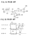
- FIGS.1A and 1B show the principle of a TCM telecommunication system, wherein FIG.1A shows a passive double star (PDS) arrangement that is one of various topologies used for optical subscriber lines.
- PDS passive double star
- a station X designated by a reference numeral 100 is connected to a plurality of subscribers A - D respectively designated as 102 - 105 via a star coupler 101, wherein the station X is connected to the star coupler 101 by a single optical fiber cable 110.
- the station thereby realizes a duplex telecommunication on the single optical fiber cable 110 by switching the transmission mode and reception mode according to a time-divisional multiplexing.
- Such a telecommunication system is called TCM-TDMA system.
- the station X When setting up the system, the station X first transmits an optical pulse to each of the subscribes A - D and measures the transmission delay to each of the subscribes A - D, by detecting returned optical pulses. Based upon the transmission delay thus measured, a transmission time slot is set for each of the subscribers A - D such that a subscriber can transmit information to the station X upon reception of transmission from the station X, without causing interference with other subscribers, as long as the transmission is made in the allocated time slot. Thereby, the transmission of information from the station X to the subscribers A - D, from the subscriber A to the station X, and from the subscriber B to the station X, are made via the time slots of respective subscribers as indicated in FIG.1B.
- FIG.2 shows a conventional optical telecommunication module 10 that constitutes a part of the conventional TCM optical telecommunication system.
- the optical telecommunication module 10 includes an optical transceiver 11 for sending out an optical transmission signal on an optical transmission line 13 provided by an optical fiber cable according to a transmission signal and for receiving an optical transmission signal incoming thereto from the optical transmission line 13, and a drive unit 12 for driving the optical transceiver 11 by the transmission signal. Further, the drive unit 12 reproduces a reception signal from the optical transmission signal received by the optical transceiver 11.
- the optical transceiver 11 and the drive unit 12 are mounted upon a printed circuit board.
- the optical transceiver 11 includes an optical coupler 14 connected to the optical transmission line 13 and an optical transmission module 15 connected to the optical coupler 14 via an optical fiber 22 as well as an optical reception module 16 connected to the optical coupler 14 via an optical fiber 24, wherein the optical transmission module 15 includes a laser diode 18 driven by a drive circuit 30 that forms a part of the drive unit 12.
- the laser diode 18 is held on a base member 17 forming a part of the optical module 15 and is coupled optically to the optical fiber 22 via a lens 20, which is held on an enclosure 21 that covers the optical transmission module 15.
- the drive circuit 30 is supplied with transmission data together with a clock signal and produces an analog drive signal that drives the laser diode 18 in response thereto.
- the optical transmission module 15 further includes a photodiode 19 on the base member 17 commonly to the laser diode 18 as indicated in FIG.3, such that the photodiode 19 detects the optical beam emitted backward from the photodiode 19.
- the photodiode 19 is biased by an APC (Automatic Power Control) circuit 31 included in the drive unit 12, and the APC circuit 31 controls the optical power of the laser diode 18 by referring to a threshold level supplied from a threshold circuit 32.
- APC Automatic Power Control
- the reception module 16 has a similar construction as indicated in FIG.3 in that a photodiode 23 is held on a base member corresponding to the base member 15 in place of the laser diode such that the photodiode 23 is coupled optically to the optical fiber 24 via a lens held on an enclosure, similarly to the lens 20 held on the enclosure 21 as shown in FIG.3.
- a photodiode corresponding to the photodiode 19 in the reception module 16.
- the photodiode 23 produces an electrical output in response to an optical signal supplied thereto via the optical fiber 24 and feeds the same to an AGC (Automatic Gain Control) circuit 34 included in the drive unit 12 via a transmission/reception switch 36.
- AGC Automatic Gain Control
- the transmission/reception switch 36 is supplied with a transmission/reception (TX/RX) control signal and activates the APC circuit 31 and the threshold circuit 32 when the TX/RX control signal indicates the transmission mode of the optical telecommunication module 10, while the switch 36 deactivates the circuits 31 and 32 when the TX/RX control signal indicates the reception mode of the optical telecommunication module 10. Thereby, a time-divisional switching of the transmission mode and reception mode is achieved for the telecommunication module 10 in response to the TX/RX control signal.
- TX/RX transmission/reception
- the switch 36 forwards the output signal of the preamplifier 33 to the AGC circuit 34 for automatic gain control, and the output signal is further forwarded to a TIM/DEC (Timing recovery/Decision) processor 35 for timing extraction, wherein the processor recovers the clock and data based upon the timing thus recovered.
- TIM/DEC Timing recovery/Decision
- the photodiode 19 monitors the optical output of the laser diode 18 by detecting the optical beam emitted backward from the laser diode 18.
- the time-dependent change of optical output occurs similarly in the forward direction and in the backward direction, no substantial problem occurs in the foregoing conventional construction.
- the change of optical beam output occurs asymmetrically in the forward direction and in the backward direction.
- the optical output in the forward direction may decrease rapidly as compared with the optical output emitted in the backward direction.
- the optical power of the optical beam emitted in the forward direction is decreased even when an APC control is applied by using the APC circuit 31, and the optical power of beam injected into the optical fiber 22 is reduced.
- the node that uses the optical telecommunication module 10 is rendered defective. Such an anomaly of the laser diode 18 cannot be detected by the photodiode 19, as long as the emission of the optical beam in the backward direction occurs normally.
- optical telecommunication module 10 has a problem of increased number of signal lines due to the construction of supplying the TX/RX control signal externally from a host TCM apparatus not illustrated in FIG.2.
- Another and more specific object of the present invention is to provide an optical telecommunication module in which optical output power of an optical beam injected into an outgoing optical fiber is directly monitored.
- Another object of the present invention is to provide an optical telecommunication module having a simplified construction.
- Another object of the present invention is to provide an optical telecommunication module, comprising:
- Another object of the present invention is to provide an optical module, comprising:
- the output power of the optical signal injected to the optical transmission line is monitored directly by the monitoring photodetection device.
- FIG.4 shows the circuit diagram of an optical telecommunication module 40 according to an embodiment of the present invention, wherein the optical telecommunication module 40 is used in a TCM optical telecommunication system as shown in FIGS.1A and 1B.
- those parts described previously are designated by the same reference numerals and the description thereof will be omitted.
- the optical telecommunication module 40 includes an optical transceiver 11A for sending out an optical transmission signal on the optical transmission line 13 according to a transmission signal and for receiving an optical transmission signal incoming thereto from the optical transmission line 13, and a drive unit 12A for driving the optical transceiver 11A by the transmission signal. Further, the drive unit 12A reproduces a reception signal from the optical transmission signal received by the optical transceiver 11A.
- the optical transceiver 11A and the drive unit 12A are mounted upon a printed circuit board.
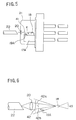
- the optical transceiver 11A includes therein an optical transmission module 15A in addition to the optical coupler 14 and the reception module 16 described already, wherein the optical transmission module 15A includes a base member 17A on which the laser diode 18 and a photodiode 19A are carried as indicated in FIG.5 such that the laser diode 18 is in alignment with an optical axis 41 of the lens 20.
- the photodiode 19A is provided in front of the laser diode 18, between the laser diode 18 and the lens 20, with an offset from the optical axis 41 in a downward direction with an offset distance e and with a tilt toward the laser diode 18.
- the laser diode 18 is coupled to the optical fiber 22 via the lens 20 and injects an optical beam cone 42a shown in FIG.6 into a core of the optical fiber 22.
- the photodiode 19A detects a marginal part 42b of the optical beam cone emitted from the laser diode 18 in the form of a divergent beam 42.
- the distance e is set such that the photodiode 19A does not interrupt the inner cone 42a of the optical beam 42 that is actually injected to the core of the optical fiber 22.
- the photodiode 19A emits an optical beam 43 in the backward direction, while the present invention does not use the optical beam 43 for the APC control.
- the photodiode 19A is connected to the APC circuit 31 similarly to the photodiode 19 of FIG.2 for controlling the laser diode 18 such that the optical output power of the laser diode 18 is maintained substantially constant.
- the APC circuit 31 controls the laser diode 18 in response to the optical output thereof emitted in the forward direction and detected by the photodiode 19A, via a drive circuit 30A, by referring to the threshold circuit 32.
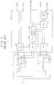
- the drive circuit 30A is supplied with data and clock as an input signal 202, similarly to the drive circuit 30 of FIG.2,
- the drive circuit 30A produces a transmission status signal 200 when driving the laser diode 18 and supplies the same to a switching signal generator 50 forming a part of the drive unit 12A.
- the transmission status signal 200 may be the drive current itself that is supplied to the laser diode 18 or a signal corresponding to the drive current.
- the switching signal generator 50 in turn produces a switching signal 201 and supplies the same to a transmission/reception switch 36A, wherein the switch 36A activates the APC circuit 31 when the transmission status signal 201 indicates a transmission mode.
- the switch 36A activates the AGC circuit 34 and forwards thereto the output of the preamplifier 33.
- the TIM/DEC processor 35 extracts clock timing from the received signal and the processor 35 further reproduces the data modulated on the reception signal based upon the clock timing thus extracted.
- the data thus reproduced is outputted from the processor 35 as an output signal 203.
- the transmission/reception switch 50 produces the switching signal 201 in response to the transmission status signal 200.
- FIGS.7A and 7B show an example of such a transmission status signal 200 and the switching signal 201, wherein it will be noted that the switching signal 201 rises immediately in response to the leading edge of the transmission status signal and falls when the low level state of the transmission status signal 200 continues for a predetermined interval.
- the switching signal 201 is supplied to the transmission/reception switch 36A together with the clock supplied to the drive circuit 30A as indicated in FIG.4, wherein the transmission/reception switch 36A controls the activation of the APC circuit 31 and the AGC circuit 34 selectively in response to the switching signal 201.
- the transmission signal 202 and the reception signal 203 are switched in accordance with a time-divisional multiplex process as indicated in FIGS.8A and 8B in response to the switching signal 201 shown in FIG.8C.
- the telecommunication module 40 has an advantageous feature that: (a) one can eliminate external transmission/reception control unit for switching the transmission mode and the reception mode; and (b) one can monitor the optical output of the laser diode directly by providing the photodiode 19 in front of the laser diode 18. Thereby, any anomaly in the emission of the optical beam is immediately detected with reliability.
- the photodiode 19A also for the photodiode 23 that detects the incoming optical signal.
- the photodiode 19A detects the incoming optical beam focused upon the optical surface of the laser diode 18 for capturing the optical beam reflected back therefrom.
Landscapes
- Engineering & Computer Science (AREA)
- Computer Networks & Wireless Communication (AREA)
- Signal Processing (AREA)
- Physics & Mathematics (AREA)
- Electromagnetism (AREA)
- Optical Communication System (AREA)
- Semiconductor Lasers (AREA)
Applications Claiming Priority (3)
| Application Number | Priority Date | Filing Date | Title |
|---|---|---|---|
| JP20425295A JP3583198B2 (ja) | 1995-08-10 | 1995-08-10 | 光通信モジュール |
| JP20425295 | 1995-08-10 | ||
| JP204252/95 | 1995-08-10 |
Publications (2)
| Publication Number | Publication Date |
|---|---|
| EP0759666A2 true EP0759666A2 (de) | 1997-02-26 |
| EP0759666A3 EP0759666A3 (de) | 2001-02-07 |
Family
ID=16487385
Family Applications (1)
| Application Number | Title | Priority Date | Filing Date |
|---|---|---|---|
| EP96112895A Withdrawn EP0759666A3 (de) | 1995-08-10 | 1996-08-09 | Optisches Nachrichtenübertragungsmodul |
Country Status (5)
| Country | Link |
|---|---|
| US (1) | US5854702A (de) |
| EP (1) | EP0759666A3 (de) |
| JP (1) | JP3583198B2 (de) |
| KR (1) | KR100194485B1 (de) |
| CN (1) | CN1148763A (de) |
Cited By (3)
| Publication number | Priority date | Publication date | Assignee | Title |
|---|---|---|---|---|
| GB2345213A (en) * | 1998-11-19 | 2000-06-28 | Nec Corp | Half-duplex infra-red transceiver that deactivates its receiver when transmitting |
| WO2001052454A1 (en) * | 1999-12-24 | 2001-07-19 | Jorge Sanchez | Electro-optic interface system and method of operation |
| USRE43685E1 (en) | 2002-01-08 | 2012-09-25 | Tecey Software Development Kg, Llc | Apparatus and method for measurement for dynamic laser signals |
Families Citing this family (42)
| Publication number | Priority date | Publication date | Assignee | Title |
|---|---|---|---|---|
| US5801866A (en) * | 1992-08-27 | 1998-09-01 | Trex Communications Corporation | Laser communication device |
| US6161009A (en) * | 1997-08-25 | 2000-12-12 | Hewlett-Packard Company | Latency time determination system for a transceiver |
| JP4300632B2 (ja) * | 1998-06-10 | 2009-07-22 | ソニー株式会社 | 光送受信装置 |
| US6460182B1 (en) * | 1999-05-11 | 2002-10-01 | Marconi Communications, Inc. | Optical communication system for transmitting RF signals downstream and bidirectional telephony signals which also include RF control signals upstream |
| US7103907B1 (en) | 1999-05-11 | 2006-09-05 | Tellabs Bedford, Inc. | RF return optical transmission |
| KR100618969B1 (ko) * | 1999-07-12 | 2006-08-31 | 삼성전자주식회사 | 광송수신 모듈 |
| KR100459708B1 (ko) * | 2002-03-29 | 2004-12-04 | 삼성전자주식회사 | 자동 레이저 출력 제어 기능을 가지는 레이저 다이오드 드라이버 |
| JP2004165299A (ja) * | 2002-11-11 | 2004-06-10 | Sumitomo Electric Ind Ltd | 光送信モジュール及び光送信器 |
| JP4245459B2 (ja) * | 2003-11-14 | 2009-03-25 | パナソニック株式会社 | 送信装置及び利得制御方法 |
| KR100768646B1 (ko) * | 2004-09-23 | 2007-10-18 | 주식회사 케이티 | 파장 잠김된 광원을 이용하는 파장분할 다중화 방식의 수동형 광 가입자망에서의 광 가입자망 장치의 광 성능 최적화 장치와 그 최적화 방법 및 이를 이용한 광성능 최적화 시스템 |
| JP4772596B2 (ja) * | 2006-06-07 | 2011-09-14 | 株式会社東芝 | Rofシステム、光受信器およびその自動調整方法 |
| US8437640B2 (en) * | 2009-02-19 | 2013-05-07 | The Boeing Company | Non-contacting signal transfer for rotating interface |
| US20100303472A1 (en) * | 2009-05-29 | 2010-12-02 | Avago Technologies Fiber Ip(Singapore) Pte. Ltd. | Apparatus and method for adaptively controlling the impulse response of the optical signal output from a laser of an optical transmitter (tx) |
| US9209901B2 (en) * | 2012-11-20 | 2015-12-08 | Telefonaktiebolaget L M Ericsson (Publ) | Configurable single-fiber or dual-fiber optical transceiver |
| TWI520510B (zh) * | 2013-03-25 | 2016-02-01 | 傳承光電股份有限公司 | 光收發裝置 |
| CN103326790A (zh) * | 2013-06-28 | 2013-09-25 | 成都思迈科技发展有限责任公司 | 可自动控制功率的光发射机 |
| CN103391137B (zh) * | 2013-08-22 | 2018-04-06 | 成都新易盛通信技术股份有限公司 | 一种带ddm功能的1×9低速率光模块 |
| JP6413675B2 (ja) | 2014-11-13 | 2018-10-31 | 住友電気工業株式会社 | 光モジュール |
| JP6772644B2 (ja) * | 2016-08-05 | 2020-10-21 | 住友電気工業株式会社 | 光モジュール |
| CN108332736A (zh) * | 2018-02-12 | 2018-07-27 | 浙江大学 | 半导体超辐射二极管光源光电探测管复用的光纤陀螺仪 |
| US11042025B2 (en) * | 2019-09-20 | 2021-06-22 | Raytheon Company | Optical data communication using micro-electro-mechanical system (MEMS) micro-mirror arrays |
| US11539131B2 (en) | 2020-08-24 | 2022-12-27 | Raytheon Company | Optical true time delay (TTD) device using microelectrical-mechanical system (MEMS) micromirror arrays (MMAS) that exhibit tip/tilt/piston (TTP) actuation |
| US11837840B2 (en) | 2020-09-01 | 2023-12-05 | Raytheon Company | MEMS micro-mirror array laser beam steerer for simultaneous illumination of multiple tracked targets |
| US11815676B2 (en) | 2020-09-17 | 2023-11-14 | Raytheon Company | Active pushbroom imaging system using a micro-electro-mechanical system (MEMS) micro-mirror array (MMA) |
| US11522331B2 (en) | 2020-09-23 | 2022-12-06 | Raytheon Company | Coherent optical beam combination using micro-electro-mechanical system (MEMS) micro-mirror arrays (MMAs) that exhibit tip/tilt/piston (TTP) actuation |
| US12372658B2 (en) | 2020-10-12 | 2025-07-29 | Raytheon Company | Negative obstacle detector using micro-electro-mechanical system (MEMS) micro-mirror array (MMA) beam steering |
| US12066574B2 (en) | 2021-01-15 | 2024-08-20 | Raytheon Company | Optical system for object detection and location using a Micro-Electro-Mechanical System (MEMS) Micro-Mirror Array (MMA) beamsteering device |
| US11477350B2 (en) | 2021-01-15 | 2022-10-18 | Raytheon Company | Active imaging using a micro-electro-mechanical system (MEMS) micro-mirror array (MMA) |
| US11550146B2 (en) | 2021-01-19 | 2023-01-10 | Raytheon Company | Small angle optical beam steering using micro-electro-mechanical system (MEMS) micro-mirror arrays (MMAS) |
| US11405114B1 (en) * | 2021-02-01 | 2022-08-02 | Lumentum Operations Llc | Automatic power control for an optical receiver |
| US11835709B2 (en) | 2021-02-09 | 2023-12-05 | Raytheon Company | Optical sensor with micro-electro-mechanical system (MEMS) micro-mirror array (MMA) steering of the optical transmit beam |
| US12372623B2 (en) | 2021-02-17 | 2025-07-29 | Raytheon Company | Conic micro-electro-mechanical system (MEMS) micro-mirror array (MMA) steered active situational awareness sensor |
| US12025790B2 (en) | 2021-02-17 | 2024-07-02 | Raytheon Company | Micro-electro-mechanical system (MEMS) micro-mirror array (MMA) and off-axis parabola (OAP) steered active situational awareness sensor |
| US11921284B2 (en) | 2021-03-19 | 2024-03-05 | Raytheon Company | Optical zoom system using an adjustable reflective fresnel lens implemented with a micro-electro-mechanical system (MEMs) micro-mirror array (MMA) |
| US11483500B2 (en) | 2021-03-24 | 2022-10-25 | Raytheon Company | Optical non-uniformity compensation (NUC) for passive imaging sensors using micro-electro-mechanical system (MEMS) micro-mirror arrays (MMAS) |
| US12130384B2 (en) | 2021-03-30 | 2024-10-29 | Raytheon Company | Multiple field-of-view (FOV) optical sensor using a micro-electro-mechanical system (MEMS) micro- mirror array (MMA) |
| US12061334B2 (en) | 2021-04-15 | 2024-08-13 | Raytheon Company | Optical scanning system using micro-electro-mechanical system (mems) micro-mirror arrays (MMAs) |
| US12360358B2 (en) | 2021-04-22 | 2025-07-15 | Raytheon Company | Micro-electro-mechanical system (MEMS) micro-mirror array (MMA) steered high-power laser transmitter |
| US12117607B2 (en) | 2021-04-28 | 2024-10-15 | Raytheon Company | Micro-electro-mechanical system (MEMS) micro-mirror array steered laser transmitter and situational awareness sensor with wavelength conversion |
| US12541098B2 (en) | 2021-08-31 | 2026-02-03 | Raytheon Company | Amplified laser device using a MEMS MMA having tip, tilt and piston capability to both correct a beam profile and steer the amplified beam |
| US11644542B2 (en) | 2021-09-20 | 2023-05-09 | Raytheon Company | Optical sensor with MEMS MMA steered transmitter and staring detector |
| US12259277B2 (en) | 2021-09-20 | 2025-03-25 | Raytheon Company | Image polarimeter using a micro-electro-mechanical system (MEMS) micro-mirror array (MMA) |
Family Cites Families (7)
| Publication number | Priority date | Publication date | Assignee | Title |
|---|---|---|---|---|
| US4292512A (en) * | 1978-06-19 | 1981-09-29 | Bell Telephone Laboratories, Incorporated | Optical monitoring photodiode system |
| US4329659A (en) * | 1979-12-27 | 1982-05-11 | Bell Telephone Laboratories, Incorporated | Feedback control of lasers in fiber optic systems |
| DE69221930T2 (de) * | 1991-05-10 | 1998-01-02 | Nippon Electric Co | Optischer Sender und Empfänger mit einem einzigen optischen Modul |
| US5359348A (en) * | 1992-05-21 | 1994-10-25 | Selectech, Ltd. | Pointing device having improved automatic gain control and information reporting |
| JP3490745B2 (ja) * | 1993-10-01 | 2004-01-26 | 日本碍子株式会社 | 複合光導波路型光デバイス |
| JP3434895B2 (ja) * | 1993-11-18 | 2003-08-11 | 富士通株式会社 | 双方向伝送用光モジュール |
| GB2285320B (en) * | 1993-12-27 | 1998-01-14 | Rohm Co Ltd | Transceiver module for optical communication |
-
1995
- 1995-08-10 JP JP20425295A patent/JP3583198B2/ja not_active Expired - Fee Related
-
1996
- 1996-08-07 KR KR1019960032818A patent/KR100194485B1/ko not_active Expired - Fee Related
- 1996-08-08 US US08/694,343 patent/US5854702A/en not_active Expired - Fee Related
- 1996-08-09 CN CN96109420A patent/CN1148763A/zh active Pending
- 1996-08-09 EP EP96112895A patent/EP0759666A3/de not_active Withdrawn
Cited By (5)
| Publication number | Priority date | Publication date | Assignee | Title |
|---|---|---|---|---|
| US6446867B1 (en) | 1995-11-22 | 2002-09-10 | Jorge Sanchez | Electro-optic interface system and method of operation |
| GB2345213A (en) * | 1998-11-19 | 2000-06-28 | Nec Corp | Half-duplex infra-red transceiver that deactivates its receiver when transmitting |
| GB2345213B (en) * | 1998-11-19 | 2004-05-05 | Nec Corp | Data communication method and apparatus for reducing power consumption |
| WO2001052454A1 (en) * | 1999-12-24 | 2001-07-19 | Jorge Sanchez | Electro-optic interface system and method of operation |
| USRE43685E1 (en) | 2002-01-08 | 2012-09-25 | Tecey Software Development Kg, Llc | Apparatus and method for measurement for dynamic laser signals |
Also Published As
| Publication number | Publication date |
|---|---|
| EP0759666A3 (de) | 2001-02-07 |
| CN1148763A (zh) | 1997-04-30 |
| JP3583198B2 (ja) | 2004-10-27 |
| KR100194485B1 (ko) | 1999-06-15 |
| US5854702A (en) | 1998-12-29 |
| KR970013899A (ko) | 1997-03-29 |
| JPH0955705A (ja) | 1997-02-25 |
Similar Documents
| Publication | Publication Date | Title |
|---|---|---|
| US5854702A (en) | Optical telecommunication module | |
| EP0512556B1 (de) | Optischer Sender und Empfänger mit einem einzigen optischen Modul | |
| JP2778967B2 (ja) | 光システムの制御 | |
| US4809286A (en) | Laser driver circuit | |
| JPH1041896A (ja) | 送受信装置および送受信方法 | |
| US4893002A (en) | Loss of optical input circuit | |
| EP0524124B1 (de) | Betriebssystem mit zwei Fasern | |
| US6567195B1 (en) | Optical network using remote optical powering of optoelectronic switch | |
| US20030058507A1 (en) | Optical transmitter and wavelength division multiplexing transmission system | |
| KR101265045B1 (ko) | 광송신기의 오발광 방지회로 | |
| CN112054848B (zh) | 光模块 | |
| JPH05145492A (ja) | 光伝送方式 | |
| JPH09181673A (ja) | 赤外線通信装置 | |
| JPH11230856A (ja) | 光パワー給電における異常検出方法及び光パワー給電装置 | |
| KR19990079076A (ko) | 광 송수신 모듈 | |
| CN110244415B (zh) | 光模块 | |
| JPH10229368A (ja) | 光空間伝送装置 | |
| EP1499041B1 (de) | Laser für optische Paketdatenübertragung in Burst-Modus Systemen | |
| JP2899617B2 (ja) | 光トランシーバのループバック試験方法 | |
| JP3184588B2 (ja) | 光アレイリンク・モジュール | |
| JP2522163B2 (ja) | 光送受信回路 | |
| CA1287904C (en) | Loss of optical input circuit | |
| JP2998795B2 (ja) | 誤接続検出機能付き受光装置 | |
| JPH05211483A (ja) | 信号処理システム並びにこれに用いる光送信装置および光受信装置 | |
| Hoss et al. | A Fiber Optically Linked 100 Channel Voice Intercom |
Legal Events
| Date | Code | Title | Description |
|---|---|---|---|
| PUAI | Public reference made under article 153(3) epc to a published international application that has entered the european phase |
Free format text: ORIGINAL CODE: 0009012 |
|
| AK | Designated contracting states |
Kind code of ref document: A2 Designated state(s): DE FR GB |
|
| PUAL | Search report despatched |
Free format text: ORIGINAL CODE: 0009013 |
|
| AK | Designated contracting states |
Kind code of ref document: A3 Designated state(s): DE FR GB |
|
| RIC1 | Information provided on ipc code assigned before grant |
Free format text: 7H 04B 10/152 A, 7G 02B 6/42 B |
|
| 17P | Request for examination filed |
Effective date: 20010806 |
|
| 17Q | First examination report despatched |
Effective date: 20031203 |
|
| GRAP | Despatch of communication of intention to grant a patent |
Free format text: ORIGINAL CODE: EPIDOSNIGR1 |
|
| STAA | Information on the status of an ep patent application or granted ep patent |
Free format text: STATUS: THE APPLICATION IS DEEMED TO BE WITHDRAWN |
|
| 18D | Application deemed to be withdrawn |
Effective date: 20041202 |