EP0760443A2 - Système de commande de pontage pour une transmission automatique - Google Patents
Système de commande de pontage pour une transmission automatique Download PDFInfo
- Publication number
- EP0760443A2 EP0760443A2 EP96113824A EP96113824A EP0760443A2 EP 0760443 A2 EP0760443 A2 EP 0760443A2 EP 96113824 A EP96113824 A EP 96113824A EP 96113824 A EP96113824 A EP 96113824A EP 0760443 A2 EP0760443 A2 EP 0760443A2
- Authority
- EP
- European Patent Office
- Prior art keywords
- lock
- automotive vehicle
- engine
- predetermined
- engaging force
- Prior art date
- Legal status (The legal status is an assumption and is not a legal conclusion. Google has not performed a legal analysis and makes no representation as to the accuracy of the status listed.)
- Granted
Links
Images



Classifications
-
- F—MECHANICAL ENGINEERING; LIGHTING; HEATING; WEAPONS; BLASTING
- F16—ENGINEERING ELEMENTS AND UNITS; GENERAL MEASURES FOR PRODUCING AND MAINTAINING EFFECTIVE FUNCTIONING OF MACHINES OR INSTALLATIONS; THERMAL INSULATION IN GENERAL
- F16H—GEARING
- F16H61/00—Control functions within control units of change-speed- or reversing-gearings for conveying rotary motion ; Control of exclusively fluid gearing, friction gearing, gearings with endless flexible members or other particular types of gearing
- F16H61/14—Control of torque converter lock-up clutches
- F16H61/143—Control of torque converter lock-up clutches using electric control means
-
- F—MECHANICAL ENGINEERING; LIGHTING; HEATING; WEAPONS; BLASTING
- F16—ENGINEERING ELEMENTS AND UNITS; GENERAL MEASURES FOR PRODUCING AND MAINTAINING EFFECTIVE FUNCTIONING OF MACHINES OR INSTALLATIONS; THERMAL INSULATION IN GENERAL
- F16H—GEARING
- F16H61/00—Control functions within control units of change-speed- or reversing-gearings for conveying rotary motion ; Control of exclusively fluid gearing, friction gearing, gearings with endless flexible members or other particular types of gearing
- F16H2061/0075—Control functions within control units of change-speed- or reversing-gearings for conveying rotary motion ; Control of exclusively fluid gearing, friction gearing, gearings with endless flexible members or other particular types of gearing characterised by a particular control method
- F16H2061/0087—Adaptive control, e.g. the control parameters adapted by learning
-
- F—MECHANICAL ENGINEERING; LIGHTING; HEATING; WEAPONS; BLASTING
- F16—ENGINEERING ELEMENTS AND UNITS; GENERAL MEASURES FOR PRODUCING AND MAINTAINING EFFECTIVE FUNCTIONING OF MACHINES OR INSTALLATIONS; THERMAL INSULATION IN GENERAL
- F16H—GEARING
- F16H61/00—Control functions within control units of change-speed- or reversing-gearings for conveying rotary motion ; Control of exclusively fluid gearing, friction gearing, gearings with endless flexible members or other particular types of gearing
- F16H61/14—Control of torque converter lock-up clutches
- F16H61/143—Control of torque converter lock-up clutches using electric control means
- F16H2061/145—Control of torque converter lock-up clutches using electric control means for controlling slip, e.g. approaching target slip value
-
- F—MECHANICAL ENGINEERING; LIGHTING; HEATING; WEAPONS; BLASTING
- F16—ENGINEERING ELEMENTS AND UNITS; GENERAL MEASURES FOR PRODUCING AND MAINTAINING EFFECTIVE FUNCTIONING OF MACHINES OR INSTALLATIONS; THERMAL INSULATION IN GENERAL
- F16H—GEARING
- F16H59/00—Control inputs to control units of change-speed- or reversing-gearings for conveying rotary motion
- F16H59/14—Inputs being a function of torque or torque demand
- F16H59/24—Inputs being a function of torque or torque demand dependent on the throttle opening
-
- F—MECHANICAL ENGINEERING; LIGHTING; HEATING; WEAPONS; BLASTING
- F16—ENGINEERING ELEMENTS AND UNITS; GENERAL MEASURES FOR PRODUCING AND MAINTAINING EFFECTIVE FUNCTIONING OF MACHINES OR INSTALLATIONS; THERMAL INSULATION IN GENERAL
- F16H—GEARING
- F16H59/00—Control inputs to control units of change-speed- or reversing-gearings for conveying rotary motion
- F16H59/36—Inputs being a function of speed
-
- F—MECHANICAL ENGINEERING; LIGHTING; HEATING; WEAPONS; BLASTING
- F16—ENGINEERING ELEMENTS AND UNITS; GENERAL MEASURES FOR PRODUCING AND MAINTAINING EFFECTIVE FUNCTIONING OF MACHINES OR INSTALLATIONS; THERMAL INSULATION IN GENERAL
- F16H—GEARING
- F16H59/00—Control inputs to control units of change-speed- or reversing-gearings for conveying rotary motion
- F16H59/36—Inputs being a function of speed
- F16H59/44—Inputs being a function of speed dependent on machine speed, e.g. the vehicle speed
-
- F—MECHANICAL ENGINEERING; LIGHTING; HEATING; WEAPONS; BLASTING
- F16—ENGINEERING ELEMENTS AND UNITS; GENERAL MEASURES FOR PRODUCING AND MAINTAINING EFFECTIVE FUNCTIONING OF MACHINES OR INSTALLATIONS; THERMAL INSULATION IN GENERAL
- F16H—GEARING
- F16H59/00—Control inputs to control units of change-speed- or reversing-gearings for conveying rotary motion
- F16H59/74—Inputs being a function of engine parameters
- F16H59/78—Temperature
-
- F—MECHANICAL ENGINEERING; LIGHTING; HEATING; WEAPONS; BLASTING
- F16—ENGINEERING ELEMENTS AND UNITS; GENERAL MEASURES FOR PRODUCING AND MAINTAINING EFFECTIVE FUNCTIONING OF MACHINES OR INSTALLATIONS; THERMAL INSULATION IN GENERAL
- F16H—GEARING
- F16H61/00—Control functions within control units of change-speed- or reversing-gearings for conveying rotary motion ; Control of exclusively fluid gearing, friction gearing, gearings with endless flexible members or other particular types of gearing
- F16H61/21—Providing engine brake control
-
- Y—GENERAL TAGGING OF NEW TECHNOLOGICAL DEVELOPMENTS; GENERAL TAGGING OF CROSS-SECTIONAL TECHNOLOGIES SPANNING OVER SEVERAL SECTIONS OF THE IPC; TECHNICAL SUBJECTS COVERED BY FORMER USPC CROSS-REFERENCE ART COLLECTIONS [XRACs] AND DIGESTS
- Y10—TECHNICAL SUBJECTS COVERED BY FORMER USPC
- Y10S—TECHNICAL SUBJECTS COVERED BY FORMER USPC CROSS-REFERENCE ART COLLECTIONS [XRACs] AND DIGESTS
- Y10S477/00—Interrelated power delivery controls, including engine control
- Y10S477/901—Control signal is slope
Definitions
- a lock-up control system for an automatic transmission of an automotive vehicle, the automotive vehicle having an internal combustion engine installed thereon, the automatic transmission having a lock-up clutch for mechanically engaging the automatic transmission with the engine to enable transmission of a driving force output from the engine to the automatic transmission, the lock-up control system controlling operation of the lock-up clutch.
- the corrected engaging force control amount-calculating means calculates the corrected engaging force control amount in a manner such that the engaging force of the lock-up clutch becomes larger as the load on the engine is larger.
- the corrected engaging force control amount-calculating means calculates the corrected engaging force control amount by correcting the learned value stored in the memory means according to the load on the engine when the load on the engine is larger than a predetermined value, and sets the corrected engaging force control amount to a predetermined value when the load on the engine is equal to or smaller than the predetermined value.
- the predetermined speed position of the automatic transmission is a third speed position, and the speed position which is suitable for the lower speed of the automotive vehicle than the predetermined speed position is a second speed position.
- the predetermined operating region includes a decelerating region in which the load on the engine is substantially equal to zero, the automatic transmission is in a speed position suitable for a higher traveling speed of the automotive vehicle than a second speed position, and at the same time the automotive vehicle is traveling at a higher speed than a predetermined value.
- the lock-up control system includes descent-determining means for determining whether the automotive vehicle is descending a slope in the decelerating region, and the learning-inhibiting means inhibits the learning means from learning the engaging force control amount when it is determined that the automotive vehicle is descending a slope in the decelerating region.
- the descent-determining means comprises operating condition continuation-determining means for determining whether the automotive vehicle has been continuously been in a predetermined operating condition over a predetermined time period, and determining means for determining that the automotive vehicle is descending a slope if a change in a traveling speed of the automotive vehicle has occurred from a value below a first predetermined value to a value above a second predetermined value higher than the first predetermined value when it is determined that the automotive vehicle has been continuously been in the predetermined operating condition over the predetermined time period.
- the predetermined operating region includes a feedback control region in which the automotive vehicle is traveling at a speed within a predetermined range determined by predetermined upper and lower limit values thereof, and at the same time load on the engine is within a predetermined range determined by predetermined upper and lower limit values thereof.
- the engine includes a throttle valve. More specifically, the predetermined operating condition of the automotive vehicle is an operating condition in which the throttle valve is substantially fully closed and at the same time a rate of decrease in rotational speed of the engine is smaller than a predetermined value.
- the ECU 2 is comprised of an input circuit having the functions of shaping the waveforms of input signals from various sensors, shifting the voltage levels of sensor output signals to a predetermined level, converting analog signals from analog output sensors to digital signals, and so forth, a central processing unit (hereinafter referred to as the CPU"), a memory device comprised of a ROM storing various operational programs which are executed by the CPU and various maps, referred to hereinafter, and a RAM for storing results of calculations from the CPU, etc., and an output circuit which outputs driving signals to the A solenoid valve 25a, the B solenoid valve 25b and the transmission actuator 25c.
- the ECU 2 operates in response to the above-mentioned signals from the sensors to control the operation of the lock-up clutch 23 and the gear position. Routines described below with reference to flowcharts are executed by the CPU of the ECU 2.
- Figs. 2 and 3 shows a routine for controlling the A solenoid valve 25a, which is executed at predetermined time intervals of e.g. 80 msec.
- the lock-up clutch 23 is engaged when the A solenoid valve 25a is energized, and disengaged or released when the latter is deenergized.
- step S3 it is determined at a step S3 whether or not a descent-determining flag FBK, which, when set to "1", indicates that the automotive vehicle is descending a slope, assumes "1". If the vehicle is descending a slope, the program proceeds to a step S4, wherein it is determined whether or not the engine rotational speed NE is higher than a predetermined reference value NLCBK (e.g. 860 rpm). If NE ⁇ NLCBK holds, the program proceeds to the step S36 via the step S13 to deenergize the A solenoid valve 25a, whereas if NE > NLCBK holds, the program proceeds to a step S6.
- NLCBK e.g. 860 rpm
- step S5 it is determined whether or not the engine rotational speed NE is higher than a predetermined reference value NLC0 (e.g. 1000 rpm). If NE ⁇ NLC0 holds, the program proceeds to the step S36 via the step S13 to deenergize the A solenoid valve 25a, whereas if NE > NLC0 holds, the program proceeds to the step S6.
- NLC0 a predetermined reference value
- step S6 it is determined whether or not the shift position is the D4 range. If the shift position is not the D4 range, it is determined at a step S9 whether or not it is the D3 range. If the shift position is neither the D4 range nor the D3 range, the program proceeds to the step S36 via the step S13, whereby the A solenoid valve 25a is deenergized.
- step S10 If the shift position is determined to be the D3 range at the step S6, it is determined at a step S10 whether or not the lock-up flag FLSC assumed "1" in the immediately preceding loop. If the lock-up flag FLSC assumed "0", the program immediately proceeds to a step S12. If the lock-up flag FLSC assumed "1", a tmLCOFF downcount timer is set to a predetermined time period TLCOFF and started at a step S11, followed by the program proceeding to the step S12. At the step S12, it is determined whether or not the count tmDLY2 of a tmDLY2 downcount timer which is set at a step S7, referred to hereinafter, is equal to "0".
- step S6 the program proceeds to the step S7, wherein the tmDLY2 downcount timer is set to a predetermined time period TDLY2 and started. Then at the following step S8, it is determined whether or not the count tmLCOFF of the tmLCOFF downcount timer set at the step S11 is equal to "0". If the tmLCOFF downcount timer was set and started at the step S11 when the shift position was the D3 range, the count tmLCOFF is larger than "0" when the step S8 is executed for the first time thereafter, so that the program immediately proceeds to a step S15.
- step S14 it is determined whether or not the count tmDLY0 of the tmDLY0 downcount timer set at the step S13 is equal to "0". As long as tmDLY0 > 0 holds, the program proceeds to the step S36, whereby the A solenoid valve 25a is deenergized.
- step S17 If DNE ⁇ DNPANIC holds at the step S15, i.e. if the decrement of the NE value is small, it is determined at a step S17 whether or not the count tmDLY1 of the tmDLY1 downcount timer set at the step S16 is equal to "0". As long as tmDLY1 > 0 holds, the program proceeds to the step S36, and when the count tmDLY1 becomes equal to "0", the program proceeds to a step S18 in Fig. 3.
- step S18 it is determined whether or not the throttle valve opening THW is larger than a predetermined reference value THIDLE with reference to which the engine is determined to be idling. If THW ⁇ THIDLE holds, it is determined at a step S25 whether or not the gear position NGRAT is a higher speed position than the second speed position (i.e. the third speed position or the fourth speed position). If NGRAT ⁇ 2 holds, which means that the gear position is the first or the second speed position, the program proceeds to the step S36, whereby the A solenoid valve 25a is deenergized.
- step S26 it is determined at a step S26 whether or not the vehicle speed VP is higher than a predetermined reference value VDECLCi (e.g. 38km/h).
- VDECLCi e.g. 38km/h.
- the suffix "i" indicates that a different value is used depending on the gear position. That is, when the gear position is the third speed position, a predetermined reference value VDECLC3 for the third speed position is used, and when the gear position is the fourth speed position, a predetermined reference value VDECLC4 for the fourth speed position is used.
- step S26 If VP ⁇ VDECLCi holds at the step S26, the program proceeds to the step S36, whereas if VP > VDECLCi holds, it is determined at a step S27 whether or not decelerating fuel cut is being carried out. If decelerating fuel cut is being carried out, the program immediately proceeds to a step S29, whereas if decelerating fuel cut is not being carried out, it is determined at a step S28 whether or not the descent-determining flag FBK assumes "1".
- step S36 If the flag FBK assumes "0", which means that the vehicle is not descending a slope, the program proceeds to the step S36, whereas if the flag FBK assumes "1", which means that the vehicle is descending a slope, the program proceeds to the step S29. This makes it possible to enlarge the operating region of the engine in which the lock-up clutch is engaged, when the vehicle is descending a slope.
- THW > THIDL holds at the step S18
- a step S19 it is determined at a step S19 whether or not the vehicle speed VP is higher than a predetermined reference value VLCSDjH (e.g. 100km/h) for the higher speed positions. If VP ⁇ VLCSDjH holds, it is determined at a step S20 whether or not the vehicle speed VP is higher than a predetermined reference value VLCSDjL (e.g. 20km/h) for the lower speed positions.
- VLCSDjL e.g. 20km/h
- the suffix "j" indicates that a different value is used depending on whether the shift position is the D3 range or the D4 range. That is, when the shift position is the D3 range, predetermined reference values VLCSD3H and VLCSD3L are used, whereas when the shift position is the D4 range, predetermined reference values VLCSD4H and VLCSD4L are used.
- the predetermined reference value THLCSj becomes larger as the vehicle speed VP increases.
- the suffix "j" indicates that different tables are provided for the D3 and D4 ranges, respectively, i.e. that a corresponding table is used depending on the shift position. However, the tables are set in a similar manner, as shown in Fig. 4, for both of the D3 range and the D4 range.
- step S22 it is determined whether or not the throttle valve opening THW is smaller than the predetermined reference value THLCSj. If THW ⁇ THLCSj holds, the program proceeds to the step S23, whereas if THW ⁇ THLCSj holds, the program proceeds to a step S24, wherein it is determined whether or not the count tmDLY3 of the tmDLY3 downcount timer set at the step S23 is equal to "0". As long as tmDLY3 > 0 holds, the program proceeds to the step S36, and when the count tmDLY3 becomes equal to "0", the program proceeds to the step S29.
- step S29 it is determined whether or not the lock-up flag FLCS assumes "1". If the flag FLCS assumes "1", the program immediately proceeds to a step S35, wherein the A solenoid valve 25a is kept energized.
- step S30 If DTH > 0 holds at the step S30, or if
- step S36 the program proceeds to the step S36, and when the count tmLCS becomes equal to "0", the program proceeds to the step S35, wherein the lock-up flag FLCS is set to "1", and at the same time the A solenoid valve 25a is energized.
- the A solenoid valve 25a is deenergized (i.e. the lock-up clutch is disengaged) regardless of the other conditions. In cases other than the above, whether the A solenoid valve 25a should be energized or deenergized (i.e.
- step S43 it is determined whether or not the engine coolant temperature TW is higher than a predetermined reference value TWLC1 (e.g. 30°C). If TW ⁇ TWLC1 holds, a CLCCWU downcounter, the count CLCCWU of which is decremented at a step S46, referred to hereinafter, and used at a step S47, referred to hereinafter, is set to a predetermined value C0 at a step S44, followed by the program proceeding to a step S57 in Fig. 6.
- a predetermined reference value TWLC1 e.g. 30°C
- step S49 it is determined at a step S49 whether or not the throttle valve opening THW is larger than the predetermined reference value THIDLE for determining the idling of the engine. If THW ⁇ THIDLE holds, the program proceeds to a step S50, wherein it is determined whether or not the gear position NGRAT is set to the third or higher speed position. If NGRAT ⁇ 3 holds, it is determined at a step S51 whether or not the vehicle speed VP is lower than a predetermined reference value VDECLCS (e.g. 70km/h).
- VDECLCS e.g. 70km/h
- step S54 it is determined at a step S54 whether or not the count tmLCC of the tmLCC downcount timer set at the step S53 is equal to "0". As long as tmLCC > 0 holds, the program proceeds to the step S57, and when the count tmLCC becomes equal to "0", the program proceeds to a step S55 in Fig. 6.
- VD3FUL e.g. 130km/h
- step S74 it is determined whether or not the DOUT value is smaller than the predetermined reference value DATON. If DOUT ⁇ DATON holds, at a step S81 the duty ratio control is set to an addition mode in which the DOUT value is gradually increased according to the result of the calculation carried out at the step S73, followed by the program proceeding to the step S85.
- step S74 the program proceeds to a step S75, wherein the control duty ratio DOUT and the integral term DI are both set to 100% (i.e. the maximum engaging force), and then the duty ratio control is set to a 100% mode at a step S76, followed by the program proceeding to the step S85.
- step S60 it is determined whether or not the vehicle speed VP is lower than a predetermined reference value VLCFB (e.g. 60km/h). If VP ⁇ VLCFB holds, the program proceeds to the step S73, whereas if VP ⁇ VLCFB holds, it is determined at steps S61 and S62 whether or not the gear position NGRAT is the fourth speed position and whether or not it is the third speed position, respectively. According to results of these determinations, the following processing is carried out:
- step S66 and S67 It is determined at steps S66 and S67 whether or not the vehicle speed VP is lower than a predetermined reference value VLCL4 (e.g. 40km/h) and higher than a predetermined reference value VLCREF4 (e.g. 20km/h), respectively. If VP ⁇ VLCREF4 holds at the step S67, the program proceeds to the step S57 (inoperative mode), whereas if VLCREF4 ⁇ VP ⁇ VLCL4 holds at the steps S66 and S67, the program proceeds to a step S70, whereas if VP ⁇ VLCL4 holds at the step S66, the program proceeds to the step S68.
- VLCL4 e.g. 40km/h
- VLCREF4 e.g. 20km/h
- a tmLCFB downcount timer used at a step S71 is set to a predetermined time period TLCFB and started, and then the program proceeds to a step S77 in Fig. 7, wherein calculation of a learned control amount DOUTR, described in detail hereinafter with reference to Fig. 11, is carried out. Then, it is determined at a step S78 whether or not the duty ratio control was executed in a learning mode (hereinafter referred to as "the REF mode") in which the learned control amount DOUTR is applied, in the immediately preceding loop.
- the REF mode a learning mode
- step S70 REF mode or addition mode
- step S77 REF mode or addition mode
- step S64 and S65 It is determined at steps S64 and S65 whether or not the vehicle speed VP is lower than a predetermined reference value VLCL3 (e.g. 30km/h), and whether or not it is higher than a predetermined reference value VLCREF3 (e.g. 20km/h), respectively. If VP ⁇ VLCREF3 holds at the step S65, the program proceeds to the step S57 (inoperative mode), whereas if VLCREF3 ⁇ VP ⁇ VLCL3 holds at the steps S64 and S65, the program proceeds to the step S70 (REF mode or addition mode). Further, if VP ⁇ VLCL3 holds at the step S64, the program proceeds to the step S68 (F/B mode, REF mode or addition mode).
- VLCL3 e.g. 30km/h
- VLCREF3 e.g. 20km/h
- a step S63 It is determined at a step S63 whether or not the vehicle speed VP is higher than a predetermined reference value VLCL2 (e.g. 20km/h). If VP ⁇ VLCL2 holds at the step S63, the program proceeds to the step S57 (inoperative mode), whereas if VP > VLCL2 holds, the program proceeds to the step S77 (REF mode or addition mode). It should be noted that VP > VLCL2 holds exclusively when the gear position is the second speed position.
- VLCL2 e.g. 20km/h
- one of the inoperative mode, the DEC mode, the F/B mode, the 100% mode, the addition mode and the REF mode is selected depending on the vehicle speed VP, the throttle valve opening THW, the gear position NGRAT and the shift position, to thereby determine the control duty ratio DOUT for the B solenoid valve 25b.
- Figs. 9 and 10 show a subroutine for carrying out the duty ratio control in the DEC mode, which is executed at the step S59 in Fig. 6.
- the learned value LREFDECi is initially set to a predetermined value.
- the program jumps to a step S96, whereas if the duty ratio control was not executed in the DEC mode, it is determined at a step S93 whether or not the absolute value
- step S96 it is determined whether or not a difference DNLC (calculated in the immediately preceding loop) between a desired value NOBDECi of the engine rotational speed and the detected value of the engine rotational speed NE (see steps S104 and S106) is smaller than a predetermined reference value DNLCLMT. If DNLC ⁇ DNLCLMT holds, a tmDEC downcount timer is set to a predetermined time period TDEC and started at a step S97, and then the program proceeds to a step S100, wherein it is determined whether or not the gear position NGRAT is the fourth speed position.
- DNLC calculated in the immediately preceding loop
- ETR NM/NE where NM represents an input rotational speed of the gear mechanism 24. ETR > 100% indicates that it is desired that an input rotational speed NM of the gear mechanism 24 should be higher than the engine rotational speed NE.
- step S98 it is determined at a step S98 whether or not the count tmDEC of the tmDEC downcount timer set at the step S97 is equal to "0". As long as tmDEC > 0 holds, the program proceeds to the step S100, and when the count tmDEC becomes equal to "0", the program proceeds to a step S99, wherein the gear position NGRAT is set to the fourth speed position, and it is determined at the step S101 whether or not the descent-determining flag FBK assumes "1".
- step S110 in Fig. 10 it is determined whether or not the DOUT value calculated at the step S109 is larger than "0". If DOUT > 0 holds, a tmDECLC downcount timer is set to a predetermined time period TDECLC and started at a step S111, followed by the program proceeding to a step S114. On the other hand, if DOUT ⁇ 0 holds, it is determined at a step S112 whether or not the count tmDECLC of the tmDECLC downcount timer set at the step S111 is equal to "0".
- the DOUT value is determined at the steps S100 to S109 such that the slip ratio ETR becomes equal to a desired value of more than 100% (i.e. NM > NE) in the DEC mode, and at the same time the learned value LREFDECi is calculated for each gear position at the step S119 or S120.
- the learned value LREFDECi is used at the step S94 or S95 as an initial value of the integral term DI immediately after transition of the processing to the DEC mode.
- the desired engine rotational speed is set at the steps S101 and S103 such that it increases when the vehicle is descending a slope, whereby the difference DNLC is increased at the step S104 to increase the control duty ratio DOUT, thereby increasing the engaging force of the lock-up clutch.
- This makes it possible to more effectively apply engine brake.
- the descent-detecting method according to the embodiment makes it possible to detect traveling on a gentle and long descent which the prior art could not detect, as will be described hereinafter. Therefore, engine brake can be effectively applied while the vehicle is descending such a gentle and long slope, as well.
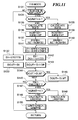
- Fig. 11 shows a subroutine for carrying out the duty ratio control in the F/B mode, which is executed at the step S72 in Fig. 6.
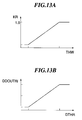
- step S161 it is determined at a step S161 whether or not the throttle valve opening THW is larger than the predetermined low load-side reference value THLCiL calculated at the step S42 in Fig. 5. If THW ⁇ THLCiL holds, the learned control amount DOUTR is set to a predetermined value DOUTRL at a step S162, followed by the program proceeding to a step S170.
- the lock-up clutch 23 is engaged even when the gear position is the second speed position, and the learned control amount DOUTR is calculated by correcting the learned value LREFFB for the third speed position according to the throttle valve opening THW to thereby control the engaging force.
- step S170 it is determined whether or not the learned control amount DOUTR is larger than a predetermined upper limit value DOUTRH. If DOUTR ⁇ DOUTRH holds, the program is immediately terminated, whereas if DOUTR > DOUTRH holds, the DOUTR value is set to the predetermined upper limit value DOUTRH at a step S171, followed by terminating the program.
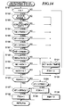
- Fig. 14 shows a routine for determining whether the vehicle is descending a slope, which is executed in synchronism with generation of each TDC signal pulse.
- a predetermined traveling condition flag FDH which, when set to "1", indicates that the vehicle is in a predetermined traveling condition, referred to hereinafter (see step S195), is reset to "0" at a step S192, and then the descent-determining flag FBK is set to "0" at a step S196, followed by terminating the program.
- a tmBK downcount timer is set to a predetermined time period TBK (e.g. a time period within a range of 5 to 10 seconds) and started at a step S191, followed by the program proceeding to the step S192. If the decrement DNE of the engine rotational speed NE is not smaller than the predetermined reference value DNEBK, the program jumps to a step S196.
- step S190 it is determined at a step S190 whether or not the count tmBK of the tmBK downcount timer is equal to "0". As long as tmBK > 0 holds, the program proceeds to the step S196, and when the count tmBK becomes equal to "0", the program proceeds to a step S193, wherein it is determined whether or not the predetermined traveling condition flag FDH assumes "1".
- the flag FDH is initially set to "0", so that the answer of the question at the step S193 which is first executed is affirmative (YES), and then the program proceeds to a step S194, wherein it is determined whether or not the vehicle speed VP is lower than a first reference value VPBK2 (e.g. 45km/h). If VP ⁇ VPBK2 holds, the program jumps to the step S196, whereas if VP ⁇ VPBK2 holds, it is judged that the engine is in the predetermined traveling condition, and then the flag FDH is set to "1" at the step S95, followed by the program proceeding to the step S196.
- VPBK2 e.g. 45km/h
- step S197 it is determined whether or not the vehicle speed VP is higher than a second reference value VPBK3 (e.g. 55km/h). If VP ⁇ VPBK3 holds, the program is immediately terminated, whereas if VP > VPBK3 holds, it is judged that the vehicle is descending a slope, and the descent-determining flag FBK is set to "1" at a step S198, followed by terminating the program.
- VPBK3 e.g. 55km/h
- VPBK1 The relationship between the reference lower limit value VPBK1, the reference upper limit value VPBK4, the first reference value VPBK2 and the second reference value VPBK3 is expressed as VPBK1 ⁇ VPBK2 ⁇ VPBK3 ⁇ VPBK4.
- Fig. 14 routine it is judged that the vehicle is descending a slope when a condition in which all the answers to the questions of the steps S182 to S189 are affirmative (YES) has continued for more than the predetermined time period TBK, and at the same time a condition in which VPBK1 ⁇ VP ⁇ VPBK3 holds has shifted to a condition in which VP > VPBK3 holds. That is, in this routine, the descent of the vehicle is not determined based on acceleration of the vehicle, and therefore it is possible to carry out an accurate descent-determination e.g. even when the vehicle is descending a long and gentle slope with little acceleration.
- the descent-determining flag FBK set as above is referred to at the step S28 in Fig. 3, whereby the A solenoid valve 25a is engaged when the vehicle is descending a slope, to thereby enlarge the operating region in which the lock-up clutch is engaged. This makes it possible to effectively apply engine brake.
- a lock-up control system for an automatic transmission of an automotive vehicle controls operation of a lock-up clutch for mechanically engaging the automatic transmission with the engine to enable transmission of a driving force output from the engine to the automatic transmission.
- An engaging force of the lock-up clutch is controlled in an predetermined operating region of the automotive vehicle, which is determined based on operating conditions of the automotive vehicle and the engine, in such a manner that an amount of slip of the lock-up clutch becomes equal to a desired value.
- An engaging force control amount for controlling the engaging force of the lock-up clutch is learned when the automotive vehicle is traveling in the predetermined operating region with the automatic transmission being in a predetermined speed position, and a learned value thus obtained is stored.
- the engaging force control amount is calculated by correcting the stored learned value according to load on the engine, when the automotive vehicle is traveling with the automatic transmission being in a speed position which is suitable for a lower traveling speed of the automotive vehicle than the predetermined speed position.
- the engaging force of the lock-up clutch is controlled by the use of the corrected engaging force control amount, when the automotive vehicle is traveling with the automatic transmission being in the above speed position which is suitable for the lower speed of the automotive vehicle.
Landscapes
- Engineering & Computer Science (AREA)
- General Engineering & Computer Science (AREA)
- Mechanical Engineering (AREA)
- Control Of Fluid Gearings (AREA)
Priority Applications (1)
| Application Number | Priority Date | Filing Date | Title |
|---|---|---|---|
| EP99111247A EP0937919B1 (fr) | 1995-08-30 | 1996-08-29 | Système de commande de pontage pour une transmission automatique |
Applications Claiming Priority (9)
| Application Number | Priority Date | Filing Date | Title |
|---|---|---|---|
| JP24386295 | 1995-08-30 | ||
| JP24386095 | 1995-08-30 | ||
| JP24386195 | 1995-08-30 | ||
| JP24386195A JP3446786B2 (ja) | 1995-08-30 | 1995-08-30 | 自動変速機のロックアップ制御装置 |
| JP243860/95 | 1995-08-30 | ||
| JP243862/95 | 1995-08-30 | ||
| JP24386095A JP3131920B2 (ja) | 1995-08-30 | 1995-08-30 | 自動変速機のロックアップ制御装置 |
| JP24386295A JP3135488B2 (ja) | 1995-08-30 | 1995-08-30 | 自動変速機のロックアップ制御装置 |
| JP243861/95 | 1995-08-30 |
Related Child Applications (1)
| Application Number | Title | Priority Date | Filing Date |
|---|---|---|---|
| EP99111247A Division EP0937919B1 (fr) | 1995-08-30 | 1996-08-29 | Système de commande de pontage pour une transmission automatique |
Publications (3)
| Publication Number | Publication Date |
|---|---|
| EP0760443A2 true EP0760443A2 (fr) | 1997-03-05 |
| EP0760443A3 EP0760443A3 (fr) | 1998-07-01 |
| EP0760443B1 EP0760443B1 (fr) | 2000-05-17 |
Family
ID=27333183
Family Applications (2)
| Application Number | Title | Priority Date | Filing Date |
|---|---|---|---|
| EP96113824A Expired - Lifetime EP0760443B1 (fr) | 1995-08-30 | 1996-08-29 | Système de commande de pontage pour une transmission automatique |
| EP99111247A Expired - Lifetime EP0937919B1 (fr) | 1995-08-30 | 1996-08-29 | Système de commande de pontage pour une transmission automatique |
Family Applications After (1)
| Application Number | Title | Priority Date | Filing Date |
|---|---|---|---|
| EP99111247A Expired - Lifetime EP0937919B1 (fr) | 1995-08-30 | 1996-08-29 | Système de commande de pontage pour une transmission automatique |
Country Status (3)
| Country | Link |
|---|---|
| US (1) | US5722912A (fr) |
| EP (2) | EP0760443B1 (fr) |
| DE (2) | DE69608377T2 (fr) |
Cited By (4)
| Publication number | Priority date | Publication date | Assignee | Title |
|---|---|---|---|---|
| EP0860633A1 (fr) * | 1997-02-17 | 1998-08-26 | ZF FRIEDRICHSHAFEN Aktiengesellschaft | Méthode de commande d'un embrayage de pontage de convertisseur de couple pendant le démarrage de véhicule |
| EP0878645A3 (fr) * | 1997-05-12 | 1999-09-01 | Mazda Motor Corporation | Système de commande d'embrayage de pontage pour convertisseur de couple hydrodynamique d'une transmission automatique |
| FR2817513A1 (fr) * | 2000-06-23 | 2002-06-07 | Luk Lamellen & Kupplungsbau | Procede et dispositif de commande pour la commande de valeurs caracteristiques de fonctionnement d'une chaine motrice |
| CN104100708A (zh) * | 2013-04-10 | 2014-10-15 | 腓特烈斯港齿轮工厂股份公司 | 用于控制系统压力调节系统的阀系统 |
Families Citing this family (26)
| Publication number | Priority date | Publication date | Assignee | Title |
|---|---|---|---|---|
| US5743829A (en) * | 1995-02-22 | 1998-04-28 | Honda Giken Kogyo Kabushiki Kaisha | Control system for vehicle automatic transmission |
| DE19544021A1 (de) * | 1995-11-25 | 1997-05-28 | Bosch Gmbh Robert | Steuerungssystem |
| US5879266A (en) * | 1997-01-17 | 1999-03-09 | Honda Giken Kogyo Kabushiki Kaisha | Control system for internal combustion engines |
| JP3900587B2 (ja) * | 1997-04-14 | 2007-04-04 | マツダ株式会社 | 自動変速機付き車両の流体継ぎ手の締結力制御装置 |
| US6077188A (en) * | 1997-12-01 | 2000-06-20 | Aisin Seiki Kabushiki Kaisha | Lock-up control method of automatic transmission |
| DE19835937A1 (de) * | 1998-08-08 | 2000-02-10 | Wabco Gmbh | Verfahren zur Regelung der Abstiegsgeschwindigkeit eines Gelände-Fahrzeugs |
| JP3635946B2 (ja) * | 1998-11-06 | 2005-04-06 | 日産自動車株式会社 | トルクコンバータのスリップ制御装置 |
| US6647332B1 (en) * | 1998-12-21 | 2003-11-11 | Caterpillar Inc | Electronic inching control strategy |
| DE19925368B4 (de) * | 1999-06-02 | 2015-01-15 | Robert Bosch Gmbh | Verfahren und Vorrichtung zur Fahrtgeschwindigkeitsregelung eines Fahrzeugs |
| JP2001099305A (ja) * | 1999-09-30 | 2001-04-10 | Nissan Motor Co Ltd | 自動変速機のロックアップ制御装置 |
| JP2002031163A (ja) * | 2000-07-12 | 2002-01-31 | Mitsubishi Electric Corp | 歯車式自動変速装置 |
| KR100380493B1 (ko) | 2000-12-28 | 2003-04-18 | 현대자동차주식회사 | 자동변속기의 댐퍼클러치 제어방법 |
| JP2002310289A (ja) * | 2001-04-11 | 2002-10-23 | Jatco Ltd | 自動変速機トルクコンバータのロックアップ制御装置 |
| JP3671394B2 (ja) * | 2001-06-26 | 2005-07-13 | 本田技研工業株式会社 | 車両用自動変速機の制御装置 |
| JP4191968B2 (ja) * | 2002-08-27 | 2008-12-03 | トヨタ自動車株式会社 | 車両用駆動制御装置 |
| DE602004031582D1 (de) * | 2003-11-12 | 2011-04-14 | Jatco Ltd | Kraftantriebsvorrichtung mit einem Drehmomentwandler mit einer Überbrückungskupplung und Überbrückungssteuerungverfahren |
| KR100569077B1 (ko) * | 2003-12-17 | 2006-04-07 | 현대자동차주식회사 | 자동 변속기의 변속시 감속 직결 제어방법 |
| KR100623763B1 (ko) * | 2003-12-30 | 2006-09-18 | 현대자동차주식회사 | 자동변속기의 감속 직결 제어방법 |
| JP4779452B2 (ja) * | 2005-06-01 | 2011-09-28 | トヨタ自動車株式会社 | 車両の制御装置 |
| FR2911656B1 (fr) * | 2007-01-19 | 2009-10-02 | Renault Sas | Procede de pilotage du glissement de l'embrayage de prise directe d'un convertisseur de couple |
| US20080254941A1 (en) * | 2007-04-11 | 2008-10-16 | Jeffery Scott | Controlling the operating states of a torque converter clutch in an automatic transmission |
| US8630778B2 (en) * | 2008-08-08 | 2014-01-14 | Honda Motor Co., Ltd. | Controlling a throttle for fuel cut acquisition |
| US8177686B2 (en) * | 2010-01-13 | 2012-05-15 | Ford Global Technologies, Llc | Transmission torque converter clutch control |
| JP5638120B2 (ja) * | 2011-03-01 | 2014-12-10 | 本田技研工業株式会社 | ロックアップクラッチの制御装置 |
| US8439799B1 (en) * | 2012-06-07 | 2013-05-14 | Honda Motor Co., Ltd. | Controller for automatic transmission |
| US9739371B1 (en) | 2016-06-14 | 2017-08-22 | Allison Transmission, Inc. | Torque converter lockup clutch slip control |
Family Cites Families (13)
| Publication number | Priority date | Publication date | Assignee | Title |
|---|---|---|---|---|
| GB2122287B (en) * | 1982-05-17 | 1985-10-09 | Honda Motor Co Ltd | Torque converter lock-up clutch control |
| GB2183308B (en) * | 1985-11-25 | 1990-08-15 | Honda Motor Co Ltd | Control for the clutch of a fluid torque converter in a vehicular transmission |
| JPS62238126A (ja) | 1986-04-09 | 1987-10-19 | Fuji Heavy Ind Ltd | 車両用自動クラツチの制御装置 |
| JPS6347561A (ja) * | 1986-08-11 | 1988-02-29 | Aisin Warner Ltd | ロツクアツプクラツチ付自動変速機 |
| JP2877302B2 (ja) | 1987-03-23 | 1999-03-31 | マツダ株式会社 | 自動変速機のロツクアツプ制御装置 |
| JPH01120479A (ja) * | 1987-10-31 | 1989-05-12 | Mazda Motor Corp | トルクコンバータのスリップ制御装置 |
| JP2571621B2 (ja) * | 1989-03-31 | 1997-01-16 | 日産自動車株式会社 | 自動変速機のロックアップ制御装置 |
| US5085301A (en) * | 1990-09-26 | 1992-02-04 | Mazda Motor Corporation | Lockup control device of a fluid transmission |
| JPH0694116A (ja) * | 1992-09-08 | 1994-04-05 | Hitachi Ltd | 自動変速制御装置 |
| JP3285960B2 (ja) * | 1992-09-16 | 2002-05-27 | マツダ株式会社 | 流体継手の締結力制御装置 |
| JP3218758B2 (ja) * | 1992-12-22 | 2001-10-15 | 株式会社デンソー | ロックアップクラッチのスリップ制御装置 |
| JP3125570B2 (ja) * | 1994-04-05 | 2001-01-22 | 日産自動車株式会社 | ロックアップ制御装置 |
| JP3152073B2 (ja) * | 1994-07-22 | 2001-04-03 | トヨタ自動車株式会社 | 車両用ロックアップクラッチのスリップ制御装置 |
-
1996
- 1996-08-29 US US08/704,989 patent/US5722912A/en not_active Expired - Lifetime
- 1996-08-29 DE DE69608377T patent/DE69608377T2/de not_active Expired - Lifetime
- 1996-08-29 EP EP96113824A patent/EP0760443B1/fr not_active Expired - Lifetime
- 1996-08-29 DE DE69616094T patent/DE69616094T2/de not_active Expired - Lifetime
- 1996-08-29 EP EP99111247A patent/EP0937919B1/fr not_active Expired - Lifetime
Cited By (9)
| Publication number | Priority date | Publication date | Assignee | Title |
|---|---|---|---|---|
| EP0860633A1 (fr) * | 1997-02-17 | 1998-08-26 | ZF FRIEDRICHSHAFEN Aktiengesellschaft | Méthode de commande d'un embrayage de pontage de convertisseur de couple pendant le démarrage de véhicule |
| EP0878645A3 (fr) * | 1997-05-12 | 1999-09-01 | Mazda Motor Corporation | Système de commande d'embrayage de pontage pour convertisseur de couple hydrodynamique d'une transmission automatique |
| US6231480B1 (en) | 1997-05-12 | 2001-05-15 | Mazda Motor Corporation | Lockup control system for fluid coupling of automatic transmission |
| FR2817513A1 (fr) * | 2000-06-23 | 2002-06-07 | Luk Lamellen & Kupplungsbau | Procede et dispositif de commande pour la commande de valeurs caracteristiques de fonctionnement d'une chaine motrice |
| WO2001098679A3 (fr) * | 2000-06-23 | 2002-08-01 | Luk Lamellen & Kupplungsbau | Procede et dispositif de commande permettant la commande de parametres de fonctionnement d'une ligne de transmission |
| US7306539B2 (en) | 2000-06-23 | 2007-12-11 | Luk Lamellen Und Kupplungsbau Beteiligungs Kg | Method and apparatus for the control of characteristic operating values of a power train |
| DE10192542B4 (de) * | 2000-06-23 | 2017-07-06 | Schaeffler Technologies AG & Co. KG | Verfahren und Steuerungseinrichtung zur Steuerung von Betriebskennwerten eines Antriebsstranges |
| CN104100708A (zh) * | 2013-04-10 | 2014-10-15 | 腓特烈斯港齿轮工厂股份公司 | 用于控制系统压力调节系统的阀系统 |
| CN104100708B (zh) * | 2013-04-10 | 2018-01-05 | 腓特烈斯港齿轮工厂股份公司 | 用于控制系统压力调节系统的阀系统 |
Also Published As
| Publication number | Publication date |
|---|---|
| DE69608377T2 (de) | 2001-04-26 |
| EP0937919B1 (fr) | 2001-10-17 |
| EP0937919A2 (fr) | 1999-08-25 |
| US5722912A (en) | 1998-03-03 |
| EP0760443A3 (fr) | 1998-07-01 |
| DE69616094D1 (de) | 2001-11-22 |
| EP0937919A3 (fr) | 1999-10-27 |
| EP0760443B1 (fr) | 2000-05-17 |
| DE69616094T2 (de) | 2002-03-14 |
| DE69608377D1 (de) | 2000-06-21 |
Similar Documents
| Publication | Publication Date | Title |
|---|---|---|
| EP0937919B1 (fr) | Système de commande de pontage pour une transmission automatique | |
| EP0715099B1 (fr) | Système de commande de la force d'entraínement d'un véhicule | |
| EP0801252B1 (fr) | Méthode de commande de changement de vitesse pour transmission automatique de véhicule | |
| EP0566399B1 (fr) | Méthode et dispositif de commande de changement de vitesse dans une transmission automatique de véhicule | |
| US5323318A (en) | System for controlling vehicle automatic transmission using fuzzy logic | |
| EP0715102B1 (fr) | Régulation des changements de vitesse d'une transmission automatique pour véhicules | |
| US6104976A (en) | Vehicle speed control system | |
| US5103398A (en) | Shift control for slip control | |
| EP0503942B1 (fr) | Méthode de commande de changement de vitesse pour transmission automatique de véhicule | |
| EP1034961B1 (fr) | Système de régulation de la force motrice dans un véhicule | |
| US5746680A (en) | Control system for automatic transmissions | |
| JP3131920B2 (ja) | 自動変速機のロックアップ制御装置 | |
| JP3135488B2 (ja) | 自動変速機のロックアップ制御装置 | |
| JP3683340B2 (ja) | 自動変速機の制御装置 | |
| KR200233635Y1 (ko) | 자동 변속기의 잠금 제어 장치 | |
| JP3446786B2 (ja) | 自動変速機のロックアップ制御装置 | |
| JP2959886B2 (ja) | 自動変速機の制御装置 | |
| KR20020071079A (ko) | 자동 변속기의 잠금 제어 장치 |
Legal Events
| Date | Code | Title | Description |
|---|---|---|---|
| PUAI | Public reference made under article 153(3) epc to a published international application that has entered the european phase |
Free format text: ORIGINAL CODE: 0009012 |
|
| AK | Designated contracting states |
Kind code of ref document: A2 Designated state(s): DE GB |
|
| PUAL | Search report despatched |
Free format text: ORIGINAL CODE: 0009013 |
|
| AK | Designated contracting states |
Kind code of ref document: A3 Designated state(s): DE GB |
|
| 17P | Request for examination filed |
Effective date: 19981102 |
|
| 17Q | First examination report despatched |
Effective date: 19990113 |
|
| GRAG | Despatch of communication of intention to grant |
Free format text: ORIGINAL CODE: EPIDOS AGRA |
|
| GRAG | Despatch of communication of intention to grant |
Free format text: ORIGINAL CODE: EPIDOS AGRA |
|
| GRAH | Despatch of communication of intention to grant a patent |
Free format text: ORIGINAL CODE: EPIDOS IGRA |
|
| GRAH | Despatch of communication of intention to grant a patent |
Free format text: ORIGINAL CODE: EPIDOS IGRA |
|
| GRAA | (expected) grant |
Free format text: ORIGINAL CODE: 0009210 |
|
| AK | Designated contracting states |
Kind code of ref document: B1 Designated state(s): DE GB |
|
| REF | Corresponds to: |
Ref document number: 69608377 Country of ref document: DE Date of ref document: 20000621 |
|
| EN | Fr: translation not filed | ||
| PLBE | No opposition filed within time limit |
Free format text: ORIGINAL CODE: 0009261 |
|
| STAA | Information on the status of an ep patent application or granted ep patent |
Free format text: STATUS: NO OPPOSITION FILED WITHIN TIME LIMIT |
|
| 26N | No opposition filed | ||
| REG | Reference to a national code |
Ref country code: GB Ref legal event code: IF02 |
|
| PGFP | Annual fee paid to national office [announced via postgrant information from national office to epo] |
Ref country code: GB Payment date: 20100825 Year of fee payment: 15 |
|
| GBPC | Gb: european patent ceased through non-payment of renewal fee |
Effective date: 20110829 |
|
| PG25 | Lapsed in a contracting state [announced via postgrant information from national office to epo] |
Ref country code: GB Free format text: LAPSE BECAUSE OF NON-PAYMENT OF DUE FEES Effective date: 20110829 |
|
| REG | Reference to a national code |
Ref country code: DE Ref legal event code: R084 Ref document number: 69608377 Country of ref document: DE Effective date: 20120523 |
|
| PGFP | Annual fee paid to national office [announced via postgrant information from national office to epo] |
Ref country code: DE Payment date: 20120822 Year of fee payment: 17 |
|
| PG25 | Lapsed in a contracting state [announced via postgrant information from national office to epo] |
Ref country code: DE Free format text: LAPSE BECAUSE OF NON-PAYMENT OF DUE FEES Effective date: 20140301 |
|
| REG | Reference to a national code |
Ref country code: DE Ref legal event code: R119 Ref document number: 69608377 Country of ref document: DE Effective date: 20140301 |