EP0760593B1 - Appareil de criblage pour moissonneuse-batteuse, notamment pour moissonneuse-batteuse pour champ experimental - Google Patents
Appareil de criblage pour moissonneuse-batteuse, notamment pour moissonneuse-batteuse pour champ experimental Download PDFInfo
- Publication number
- EP0760593B1 EP0760593B1 EP95919272A EP95919272A EP0760593B1 EP 0760593 B1 EP0760593 B1 EP 0760593B1 EP 95919272 A EP95919272 A EP 95919272A EP 95919272 A EP95919272 A EP 95919272A EP 0760593 B1 EP0760593 B1 EP 0760593B1
- Authority
- EP
- European Patent Office
- Prior art keywords
- frame
- pivoting
- chassis
- actuating
- actuating shaft
- Prior art date
- Legal status (The legal status is an assumption and is not a legal conclusion. Google has not performed a legal analysis and makes no representation as to the accuracy of the status listed.)
- Expired - Lifetime
Links
Images


Classifications
-
- A—HUMAN NECESSITIES
- A01—AGRICULTURE; FORESTRY; ANIMAL HUSBANDRY; HUNTING; TRAPPING; FISHING
- A01F—PROCESSING OF HARVESTED PRODUCE; HAY OR STRAW PRESSES; DEVICES FOR STORING AGRICULTURAL OR HORTICULTURAL PRODUCE
- A01F12/00—Parts or details of threshing apparatus
- A01F12/44—Grain cleaners; Grain separators
- A01F12/446—Sieving means
- A01F12/448—Sieve adjusting means
Definitions
- the invention relates to a screening device for a combine harvester, in particular a trial combine harvester, according to the preamble of claim 1 or 2.
- chaff and. Like. mixed crop Combine harvesters are used to clean these additives provided in connection with a preparation floor, which in cooperation with remove the admixtures from the air flow of a cleaning fan.
- This The cleaning effect depends, among other things, on the angle of attack of the cleaning sieves, especially with comparatively short cleaning sieves, as is the case with experimental field combines the case is, and can therefore also be adjusted via an inclination the cleaning sieves on different types of fruit or on the amount of threshing material, different population densities can be adjusted.
- it is known to provide inserts with different inclinations for the cleaning screens however, what a change in the inclination of the screen when cleaning screens are used excludes.
- the invention is therefore based on the object of a screening device for a Combine harvesters, especially a trial combine, with simple constructive Means to improve so that an easy to handle, all requirements sufficient inclination adjustment of the cleaning screens is possible.
- the invention solves the problem Task in that the adjusting device from two, each belonging to a frame, parallel to their transverse axes, each connected to a rotary drive
- the actuation shafts each at least one with a handlebar associated frame have connected pivot arm, and that the actuating shaft for one frame is held in the chassis, while the actuating shaft for the other frame either on the frame with that in the chassis held actuation shaft or as a coaxial hollow shaft on the in the chassis held actuating shaft is supported, the swivel drives for the two are mutually coaxially enclosing actuating shafts.
- a screening device with a around a transverse axis in the chassis pivoting frame for a cleaning screen and with an adjustment device from a parallel to the transverse axis, mounted in the chassis and to one Actuator shaft connected to the swivel drive
- the at least one has a pivot arm connected to the frame by a handlebar, so that Carry cleaning sieve a hinged end portion, the adjusting device in addition to the actuating shaft for the frame mounted in the chassis Has actuating shaft for the articulated end portion of the cleaning screen, the at least a handlebar and a swivel arm with the associated Actuating shaft is drive-connected, either on the frame or as coaxial hollow shaft on the actuating shaft associated with the frame, in which case the rotary actuators for the two coaxially enclosing each other Actuating shafts must be able to be coupled.
- the cleaning screen of such a screening device is therefore articulated into two sections, under the end section to be able to make a larger angle of inclination than the rest of the sieve.
- the adjustment device again allows the inclination to be adjusted independently of one another of the two screen sections or their common adjustment.
- the swivel drives for the two each other coaxially enclosing actuating shafts each consisting of a swivel lever and one
- the locking devices have locking disks that can be rotated together about the axis of the actuating shafts. If one of the two swivel levers is actuated, it will be operated with it connected actuating shaft only adjusts the associated frame or screen section. For the joint actuation of both actuation shafts only need the two locking disks to be rotated via a common drive.
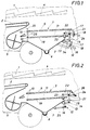
- chassis 1 of the test field combine shown is in the usual way the threshed material from the threshing drum over the Threshing basket accepting conveyor floor 2 in the form of a rotating conveyor belt provided that the with short straw, chaff u.
- Mixed crops to a screening device 3 forwards while the straw and the rest through the concave excreted plant parts are discharged via a shaker 4.
- the Screening device 3 interacts with a cleaning fan 5, which is for one sifting air flow through the screening device 3 provides.
- baffles 6 (Fig. 3) can be found below the screening device 3 may be provided.
- the crop cleaned by the screening device 3 becomes collected in a collecting funnel 7 and for example via a pneumatic Delivery line 8 discharged.
- the screening device 3 itself consists according to FIGS. 1 and 2 of two one above the other arranged frame 9 and 19, each about a transverse axis 10 in the chassis 1st are pivotally adjustable and an insertion guide for a cleaning screen 11 form so that the screening device 3 with different cleaning screens as required 11 can be equipped.
- the tilt adjustment of the frame 9 takes place via an adjusting device 12, which is parallel to the transverse axis 10 of the frame 9,
- Actuating shaft 13 mounted in the chassis 1 has swivel arms on both sides 14 sit, between which and the frame 9 link 15 are articulated.
- a manually operable pivot lever 16 On One end of the operating shaft 13 is a manually operable pivot lever 16 provided, the rotational positions locked by means of a locking device 17 can be.
- This locking device 17 consists essentially of a perforated strip, in the holes a locking pin provided on the pivot lever 16 18 snaps into place. If the pivot lever 16 is pivoted after unlocking, so the swivel arms 14 are rotated via the actuating shaft 13, which is a corresponding height shift of the frame 9 via the handlebar 15 and thus a Tilt adjustment of the upper cleaning screen 11 about the pivot axis 10 of the Frame 9 has the consequence.
- the swivel drives for the actuating shafts 13 and 21 do not need to be operated by hand to be adjusted. It can also be advantageous to use remote-controlled, motorized Actuators are provided, as illustrated in FIG. 2, the for adjusting the actuation shafts 13 and 21 on the pivot levers 16 and 24 attacking pivot cylinder 25 and 26 shows. This swivel cylinder can also the selected sieve inclination is locked. It doesn't need to be stressed be that only a swivel cylinder for preferably the actuating shaft 13th can be used because in general after a basic setting of mutual inclination of the two cleaning screens 11 both cleaning screens only be adjusted together, e.g. B. to adjust the screen inclinations to the respective Terrain slope.
- the adjustment device shown in FIG. 1 can 12 also for the adjustment of a cleaning sieve articulated into two sections 11 can be used.
- the one stored in the chassis 1 Actuating shaft 13 of the frame 9 for the cleaning screen 11 is adjusted while the Actuating shaft mounted on the frame 9 with the articulated end section 27 of the cleaning screen 11 is drive-connected.
- the pivot lever 16 By means of the pivot lever 16, the can of course be operated again by a motor drive thus the entire cleaning screen 11 pivots its end portion 27 for itself via the pivot lever 24 in its inclination relative to the frame 9 and the remaining sieve section is set.
- FIGS. 4 and 5 Another possibility of adjusting the inclination of two superimposed ones Cleaning screens are shown in FIGS. 4 and 5.
- the adjusting device 12 has in addition to the operating shaft 13 mounted in the chassis 1, a hollow confirmation shaft 28 on, which surrounds the actuating shaft 13 coaxially and independently of it can be twisted. While the operating shaft 13 via the swivel arms 14 and the handlebar 15 engages the frame 9 for the upper cleaning sieve, the Frame 19 for the lower cleaning screen via swivel arms 29 and handlebars 30 from the hollow actuating shaft 28 is adjusted.
- Swivel arms 16 and 31 with locking devices in the form of segment-shaped Locking disks 32 cooperate, which can rotate freely on the high Actuating shaft 28 are mounted and only together by means of a swivel cylinder 33 can be rotated. Since on the pivot levers 16 and 31 against spring force axially displaceable locking body 34 seated in the locking recesses 35 of the locking washers 32 engage, there is a locking of the pivot levers 16 and 31st opposite the locking washers 32, so that both actuating shafts 14 and 28 together can be adjusted via the swivel cylinder 33. A mutual swivel adjustment the frames 9 and 19 are made using the manually adjustable swivel levers 16 and 31 after their unlocking.
Landscapes
- Life Sciences & Earth Sciences (AREA)
- Environmental Sciences (AREA)
- Threshing Machine Elements (AREA)
- Combined Means For Separation Of Solids (AREA)
Claims (3)
- Dispositif de criblage pour une moissonneuse-batteuse, en particulier pour une moissonneuse-batteuse pour champ expérimental, avec deux cadres (9, 19) disposés l'un au-dessus de l'autre, montes chacun de façon à pouvoir pivoter autour d'un axe transversal (10) dans le bâti de roulage (1), chaque cadre pour un crible de nettoyage (11), et avec un dispositif de réglage destiné aux cadres (9, 19), caractérisé en ce que le dispositif de réglage (12) est constitué de deux arbres d'actionnement (13, 21, respectivement 28) appartenant chacun à un cadre (9, 19), parallèles à leurs axes transversaux (10), raccordés chacun à un entraínement pivotant, arbres d'actionnement présentant chacun au moins un bras pivotant (14, 22, respectivement 29) relié, par un bras articulé (15, 23, respectivement 30), aux cadres (9, 19) afférents, et en ce que l'arbre d'actionnement (13), destiné à un cadre (9), est maintenu dans le bâti de roulage (1), tandis que l'arbre d'actionnement (21), destiné à l'autre cadre (19), est monté à rotation soit sur le cadre (9) avec l'arbre d'actionnement (13) maintenu dans le bâti de roulage (1), soit tourillonne, à titre d'arbre creux coaxial, sur l'arbre d'actionnement (13) fixé dans le bâti de roulage (1), les entraínements de pivotement, destinés aux deux arbres (13, 28), s'entourant coaxialement l'un l'autre, étant susceptibles d'être accouplés.
- Dispositif de criblage pour une moissonneuse-batteuse, en particulier une moissonneuse-batteuse pour champ expérimental, avec un cadre (9), monté pivotant autour d'un axe transversal (10) dans le bâti de roulage (1) et destiné à un tamis de nettoyage (11), et un avec un dispositif de réglage (12) constitué d'un arbre d'actionnement (13) parallèle à l'axe transversal (10) monté à rotation dans le bâti de roulage (1) et raccordé à un entraínement de pivotement et présentant au moins un bras pivotant (14) relié, par l'intermédiaire d'un bras articulé (15), au cadre (9), caractérisé en ce que le tamis de nettoyage (11) porte une section d'extrémité (27) articulée, et en ce que le dispositif de réglage (12) présente, à côté de l'arbre d'actionnement (13) tourillonnant dans le bâti de roulage (1), pour le cadre (9), un autre arbre d'actionnement (21), destiné à la section d'extrémité (27) articulée du tamis de nettoyage (11), qui est reliée en entraínement, au moins par l'intermédiaire d'un bras articulé (23) et d'un bras pivotant (22), à l'arbre d'actionnement (21) afférent, qui est monté soit sur le cadre (9) soit, à titre d'arbre creux coaxial, sur l'arbre d'actionnement (13) appartenant au cadre (9), les entraínements de pivotement destinés aux deux arbres d'actionnement (13, 28), s'entourant l'un l'autre de façon coaxiale, étant susceptibles d'être accouplés.
- Dispositif de criblage selon la revendication 1 ou 2, caractérisé en ce que les entraínements pivotants destinés aux deux arbres d'actionnement (13, 28), s'entourant coaxialement l'un l'autre, sont chacun constitués d'un levier pivotant (16, 31) et d'un dispositif à encliquetage pour le levier pivotant (16, respectivement 31), les dispositifs à encliquetage présentant des disques d'encliquetage (32) réglables en rotation conjointement autour de l'axe des arbres d'actionnement (13, 28).
Applications Claiming Priority (3)
| Application Number | Priority Date | Filing Date | Title |
|---|---|---|---|
| AT0108694A AT401596B (de) | 1994-05-27 | 1994-05-27 | Siebvorrichtung für einen mähdrescher, insbesondere für einen versuchsfeldmähdrescher |
| AT1086/94 | 1994-05-27 | ||
| PCT/AT1995/000101 WO1995032609A1 (fr) | 1994-05-27 | 1995-05-24 | Appareil de criblage pour moissonneuse-batteuse, notamment pour moissonneuse-batteuse pour champ experimental |
Publications (2)
| Publication Number | Publication Date |
|---|---|
| EP0760593A1 EP0760593A1 (fr) | 1997-03-12 |
| EP0760593B1 true EP0760593B1 (fr) | 1998-08-26 |
Family
ID=3506287
Family Applications (1)
| Application Number | Title | Priority Date | Filing Date |
|---|---|---|---|
| EP95919272A Expired - Lifetime EP0760593B1 (fr) | 1994-05-27 | 1995-05-24 | Appareil de criblage pour moissonneuse-batteuse, notamment pour moissonneuse-batteuse pour champ experimental |
Country Status (7)
| Country | Link |
|---|---|
| US (1) | US5795223A (fr) |
| EP (1) | EP0760593B1 (fr) |
| AT (1) | AT401596B (fr) |
| DE (1) | DE59503351D1 (fr) |
| DK (1) | DK0760593T3 (fr) |
| FI (1) | FI105007B (fr) |
| WO (1) | WO1995032609A1 (fr) |
Cited By (1)
| Publication number | Priority date | Publication date | Assignee | Title |
|---|---|---|---|---|
| CN108144846A (zh) * | 2017-12-22 | 2018-06-12 | 东北农业大学 | 谷物清选双层筛纵向水平倾角伺动调节机构 |
Families Citing this family (28)
| Publication number | Priority date | Publication date | Assignee | Title |
|---|---|---|---|---|
| CA2214867C (fr) * | 1997-09-08 | 2001-03-13 | Pembina Colony Ltd. | Reglage a distance du tamis d'une moissonneuse-batteuse |
| US6066045A (en) * | 1998-08-06 | 2000-05-23 | Noomen; Wayne | Combine tray lift |
| DE19931844A1 (de) * | 1999-07-09 | 2001-01-11 | Claas Selbstfahr Erntemasch | Einrichtung zur Verstellung der Sieböffnungsweite an Mähdreschern |
| US6463722B1 (en) | 2000-01-06 | 2002-10-15 | Seco Packing | Leafy vegetable harvester and method |
| DE10111531A1 (de) | 2001-03-10 | 2002-09-26 | Deere & Co | Sieb für einen Mähdrescher |
| US6632136B2 (en) | 2001-06-05 | 2003-10-14 | Deere & Company | Remote adjustment mechanism for a combine harvester cleaning element |
| BRPI0413633A (pt) | 2003-08-19 | 2006-10-17 | James Straeter | sapata de máquina combinada de ceifar e debulhar controlada por fluxo de ar |
| US20060270473A1 (en) * | 2004-08-19 | 2006-11-30 | James Straeter | Combine shoe with airflow-control |
| US7371162B2 (en) * | 2006-04-24 | 2008-05-13 | Cnh America Llc | Sieve adjustment mechanism for an agricultural combine |
| US7572180B2 (en) * | 2007-02-13 | 2009-08-11 | Cnh America Llc | Distribution leveling for an agricultural combine |
| US20120315964A1 (en) * | 2011-06-10 | 2012-12-13 | Agco Corporation | Air diverter for combine shoe |
| WO2013016473A1 (fr) * | 2011-07-27 | 2013-01-31 | Agco Corporation | Géométrie pour la régulation de la vitesse de l'air dans une moissonneuse batteuse |
| US9814184B2 (en) * | 2011-11-09 | 2017-11-14 | Cnh Industrial America Llc | Crop material flow control system |
| DE102011085977A1 (de) * | 2011-11-09 | 2013-05-16 | Deere & Company | Sieb für eine Reinigungseinrichtung eines Mähdreschers |
| US8801512B2 (en) * | 2011-12-19 | 2014-08-12 | Agco Corporation | Method for measuring air efficiency and efficacy in a combine harvester |
| US8608534B1 (en) * | 2012-09-25 | 2013-12-17 | Agco Corporation | Rolled secondary cut off in air distribution system of a combine harvester |
| US20140128133A1 (en) * | 2012-11-02 | 2014-05-08 | Agco Corporation | Harvester having chaffer with tiltable section |
| GB201221347D0 (en) * | 2012-11-28 | 2013-01-09 | Agco As | Crop processing apparatus in a combine harvester |
| US9033779B2 (en) * | 2012-11-29 | 2015-05-19 | Cnh Industrial America Llc | Air diverter for a cleaning system of a combine harvester |
| BE1021101B1 (nl) * | 2013-07-12 | 2015-11-16 | Cnh Industrial Belgium Nv | Reinigingsgeheel voor een oogstmachine |
| WO2016154802A1 (fr) * | 2015-03-27 | 2016-10-06 | Nestec S.A. | Mécanisme de changement de maille, granulateur et procédé de changement de maille |
| CN105660034B (zh) * | 2016-01-25 | 2017-12-12 | 重庆硕奥科技有限公司 | 一种用于联合收割机的可调式筛面固定装置 |
| CN106385999B (zh) * | 2016-08-29 | 2019-06-28 | 江苏大学 | 切流与纵轴流装置脱粒分离负荷的自适应调控系统 |
| US10512217B2 (en) * | 2017-08-23 | 2019-12-24 | Deere & Company | Metering flow of grain to a cleaning device |
| US10757863B2 (en) * | 2018-06-22 | 2020-09-01 | Cnh Industrial America Llc | Device and method for changing cleaning shoe shaker arm angle |
| US11064656B1 (en) * | 2020-11-02 | 2021-07-20 | Ronald J. Kile | Combine chaffer with chaffer dam |
| CN113083666B (zh) * | 2021-03-29 | 2022-08-09 | 东北农业大学 | 可变倾角籽粒筛选装置 |
| US20240065172A1 (en) * | 2022-08-23 | 2024-02-29 | Agco Corporation | Grain Cleaning System for a Combine Harvester |
Family Cites Families (14)
| Publication number | Priority date | Publication date | Assignee | Title |
|---|---|---|---|---|
| DE69861C (de) * | H. SUMPF in Salzdetfurth, Hannover | Vorrichtung zum Stellen des beweglichen Siebes an Göpeldreschmaschinen | ||
| US680187A (en) * | 1899-04-21 | 1901-08-06 | Orrin C Zimmerman | Grain thresher and separator. |
| US1243284A (en) * | 1917-08-06 | 1917-10-16 | Austin S Goodman | Grain-separator. |
| US1383918A (en) * | 1920-07-30 | 1921-07-05 | Adolph R Fadness | Adjustable sieve-holder for threshing-machines |
| US2441917A (en) * | 1945-08-30 | 1948-05-18 | Dion Amedee | Auxiliary chaffer for threshing machines |
| FR1079152A (fr) * | 1953-04-09 | 1954-11-26 | Perfectionnements aux moissonneuses-batteurses | |
| FR1194881A (fr) * | 1958-04-18 | 1959-11-13 | Moissonneuse-batteuse perfectionnée | |
| FR1196138A (fr) * | 1958-05-13 | 1959-11-20 | Nettoyeur complémentaire de céréales ou graines adaptable sur moissonneuses batteuses tous types | |
| US3757797A (en) * | 1969-04-22 | 1973-09-11 | B Mathews | Combine |
| US3734102A (en) * | 1971-11-01 | 1973-05-22 | Mathews B C | Drive for orbiting sieve of combine |
| EP0178018B1 (fr) * | 1984-10-11 | 1989-09-06 | FORD NEW HOLLAND, INC. (a Delaware corp.) | Mécanisme de nivellement pour l'appareil de nettoyage d'une moissonneuse-batteuse |
| US4535788A (en) * | 1984-10-11 | 1985-08-20 | Sperry Corporation | Lateral leveling mechanism for combine cleaning apparatus |
| US4712568A (en) * | 1986-03-10 | 1987-12-15 | New Holland Inc. | Combine sieve adjustment mechanism |
| JP3295980B2 (ja) * | 1992-10-09 | 2002-06-24 | 井関農機株式会社 | コンバインの脱穀揺動選別装置 |
-
1994
- 1994-05-27 AT AT0108694A patent/AT401596B/de not_active IP Right Cessation
-
1995
- 1995-05-24 DE DE59503351T patent/DE59503351D1/de not_active Expired - Fee Related
- 1995-05-24 DK DK95919272T patent/DK0760593T3/da active
- 1995-05-24 EP EP95919272A patent/EP0760593B1/fr not_active Expired - Lifetime
- 1995-05-24 US US08/750,317 patent/US5795223A/en not_active Expired - Fee Related
- 1995-05-24 WO PCT/AT1995/000101 patent/WO1995032609A1/fr not_active Ceased
-
1996
- 1996-11-25 FI FI964683A patent/FI105007B/fi active
Cited By (1)
| Publication number | Priority date | Publication date | Assignee | Title |
|---|---|---|---|---|
| CN108144846A (zh) * | 2017-12-22 | 2018-06-12 | 东北农业大学 | 谷物清选双层筛纵向水平倾角伺动调节机构 |
Also Published As
| Publication number | Publication date |
|---|---|
| AT401596B (de) | 1996-10-25 |
| FI964683A0 (fi) | 1996-11-25 |
| DK0760593T3 (da) | 1999-05-25 |
| FI964683L (fi) | 1996-11-27 |
| ATA108694A (de) | 1996-03-15 |
| DE59503351D1 (de) | 1998-10-01 |
| FI105007B (fi) | 2000-05-31 |
| US5795223A (en) | 1998-08-18 |
| WO1995032609A1 (fr) | 1995-12-07 |
| EP0760593A1 (fr) | 1997-03-12 |
Similar Documents
| Publication | Publication Date | Title |
|---|---|---|
| EP0760593B1 (fr) | Appareil de criblage pour moissonneuse-batteuse, notamment pour moissonneuse-batteuse pour champ experimental | |
| DE60013249T2 (de) | Anpassungsfähigkeit bei axialflussmähdreschern | |
| EP1348331B1 (fr) | Moisonneuse-batteuse avec tamis | |
| EP2796032B1 (fr) | Moissonneuse-batteuse dotée d'un dispositif de nettoyage | |
| DE2132217C2 (de) | Vorrichtung zur Dreschkorbverstellung | |
| DE69324672T2 (de) | Anzeigevorrichtung für den eingestellten Lamellenwinkel in einer Erntemaschine | |
| DE60300431T2 (de) | Werkzeug und Verfahren zum Ein- und Ausbauen von Dreschkörben | |
| EP1716736B1 (fr) | Moissonneuse-batteuse | |
| EP0657095B1 (fr) | Moissonneuse batteuse équipée d'un hache-paille | |
| DE60217275T2 (de) | Schwenkbarer sowie schwingender Spreuboden für einen Mähdrescher | |
| EP1151654B1 (fr) | Machine de récolte en particulier faucheuse-hacheuse automotrice | |
| DE2355792C2 (fr) | ||
| DE2836099B2 (de) | Mähdrescher mit am Ende eines Strohausfallschachtes angeordnetem Häcksler | |
| DE4016878A1 (de) | Vorrichtung zur gleichmaessigen gutverteilung bei maehdreschern | |
| EP1083784A1 (fr) | Moissonneuse automotrice pourvue de cribles a lamelles reglables | |
| DE4218610C2 (de) | Verstelleinrichtung für einen Separierkorb | |
| EP2011383B1 (fr) | Moissonneuse dotée d'un dispositif de coupe | |
| WO2001047343A1 (fr) | Faucheuse-conditionneuse | |
| DE4429384C1 (de) | Aufnahme- und Sicherungseinrichtung für Schneidwerke | |
| DE102004014306A1 (de) | Strohleitrechen | |
| EP1530895B1 (fr) | Moissoneuse batteuse à recueil de cailloux | |
| DE102004001967B4 (de) | Vorrichtung zur Positionierung eines Arbeitsorgans an einem Mähdrescher | |
| DE10025030A1 (de) | Erntemaschine mit lösbar gekuppeltem Lamellensieb | |
| DE102024121506A1 (de) | Siebzusammenbau für eine Mähdrescherreinigung | |
| DE102023109126A1 (de) | Selbstfahrender Mähdrescher |
Legal Events
| Date | Code | Title | Description |
|---|---|---|---|
| PUAI | Public reference made under article 153(3) epc to a published international application that has entered the european phase |
Free format text: ORIGINAL CODE: 0009012 |
|
| 17P | Request for examination filed |
Effective date: 19961126 |
|
| AK | Designated contracting states |
Kind code of ref document: A1 Designated state(s): DE DK FR |
|
| 17Q | First examination report despatched |
Effective date: 19970402 |
|
| GRAG | Despatch of communication of intention to grant |
Free format text: ORIGINAL CODE: EPIDOS AGRA |
|
| GRAG | Despatch of communication of intention to grant |
Free format text: ORIGINAL CODE: EPIDOS AGRA |
|
| GRAH | Despatch of communication of intention to grant a patent |
Free format text: ORIGINAL CODE: EPIDOS IGRA |
|
| GRAH | Despatch of communication of intention to grant a patent |
Free format text: ORIGINAL CODE: EPIDOS IGRA |
|
| GRAA | (expected) grant |
Free format text: ORIGINAL CODE: 0009210 |
|
| AK | Designated contracting states |
Kind code of ref document: B1 Designated state(s): DE DK FR |
|
| REF | Corresponds to: |
Ref document number: 59503351 Country of ref document: DE Date of ref document: 19981001 |
|
| ET | Fr: translation filed | ||
| REG | Reference to a national code |
Ref country code: DK Ref legal event code: T3 |
|
| PLBE | No opposition filed within time limit |
Free format text: ORIGINAL CODE: 0009261 |
|
| STAA | Information on the status of an ep patent application or granted ep patent |
Free format text: STATUS: NO OPPOSITION FILED WITHIN TIME LIMIT |
|
| 26N | No opposition filed | ||
| PGFP | Annual fee paid to national office [announced via postgrant information from national office to epo] |
Ref country code: FR Payment date: 20010523 Year of fee payment: 7 |
|
| PGFP | Annual fee paid to national office [announced via postgrant information from national office to epo] |
Ref country code: DK Payment date: 20020521 Year of fee payment: 8 |
|
| PG25 | Lapsed in a contracting state [announced via postgrant information from national office to epo] |
Ref country code: FR Free format text: LAPSE BECAUSE OF NON-PAYMENT OF DUE FEES Effective date: 20030131 |
|
| REG | Reference to a national code |
Ref country code: FR Ref legal event code: ST |
|
| PGFP | Annual fee paid to national office [announced via postgrant information from national office to epo] |
Ref country code: DE Payment date: 20030530 Year of fee payment: 9 |
|
| PG25 | Lapsed in a contracting state [announced via postgrant information from national office to epo] |
Ref country code: DK Free format text: LAPSE BECAUSE OF NON-PAYMENT OF DUE FEES Effective date: 20031201 |
|
| REG | Reference to a national code |
Ref country code: DK Ref legal event code: EBP |
|
| PG25 | Lapsed in a contracting state [announced via postgrant information from national office to epo] |
Ref country code: DE Free format text: LAPSE BECAUSE OF NON-PAYMENT OF DUE FEES Effective date: 20041201 |