EP0760936B2 - Capteur à jauges de contrainte et amplificateur de modulation pour un circuit à pont - Google Patents
Capteur à jauges de contrainte et amplificateur de modulation pour un circuit à pont Download PDFInfo
- Publication number
- EP0760936B2 EP0760936B2 EP95924202A EP95924202A EP0760936B2 EP 0760936 B2 EP0760936 B2 EP 0760936B2 EP 95924202 A EP95924202 A EP 95924202A EP 95924202 A EP95924202 A EP 95924202A EP 0760936 B2 EP0760936 B2 EP 0760936B2
- Authority
- EP
- European Patent Office
- Prior art keywords
- strain gauge
- amplifier
- bridge
- demodulator
- wire strain
- Prior art date
- Legal status (The legal status is an assumption and is not a legal conclusion. Google has not performed a legal analysis and makes no representation as to the accuracy of the status listed.)
- Expired - Lifetime
Links
- 230000001419 dependent effect Effects 0.000 claims description 11
- 239000000919 ceramic Substances 0.000 claims description 2
- 230000000717 retained effect Effects 0.000 claims 1
- 238000005259 measurement Methods 0.000 abstract description 18
- 238000005303 weighing Methods 0.000 abstract description 6
- 230000008901 benefit Effects 0.000 description 6
- 238000012545 processing Methods 0.000 description 6
- 238000012937 correction Methods 0.000 description 5
- 238000000034 method Methods 0.000 description 5
- 230000010363 phase shift Effects 0.000 description 5
- 230000003321 amplification Effects 0.000 description 4
- 238000003199 nucleic acid amplification method Methods 0.000 description 4
- 230000002277 temperature effect Effects 0.000 description 4
- 238000011144 upstream manufacturing Methods 0.000 description 4
- 230000000694 effects Effects 0.000 description 3
- 238000005516 engineering process Methods 0.000 description 3
- 238000011156 evaluation Methods 0.000 description 3
- 230000001939 inductive effect Effects 0.000 description 3
- 230000010354 integration Effects 0.000 description 3
- 239000003990 capacitor Substances 0.000 description 2
- 230000000295 complement effect Effects 0.000 description 2
- 238000010276 construction Methods 0.000 description 2
- 238000010586 diagram Methods 0.000 description 2
- 230000001965 increasing effect Effects 0.000 description 2
- 239000000463 material Substances 0.000 description 2
- 239000002184 metal Substances 0.000 description 2
- 238000006243 chemical reaction Methods 0.000 description 1
- 238000004891 communication Methods 0.000 description 1
- 239000002131 composite material Substances 0.000 description 1
- 238000013461 design Methods 0.000 description 1
- 239000011888 foil Substances 0.000 description 1
- 230000007935 neutral effect Effects 0.000 description 1
- 238000007781 pre-processing Methods 0.000 description 1
- 238000003672 processing method Methods 0.000 description 1
- 230000002787 reinforcement Effects 0.000 description 1
- 230000002441 reversible effect Effects 0.000 description 1
- 230000005676 thermoelectric effect Effects 0.000 description 1
Images


Classifications
-
- H—ELECTRICITY
- H03—ELECTRONIC CIRCUITRY
- H03F—AMPLIFIERS
- H03F3/00—Amplifiers with only discharge tubes or only semiconductor devices as amplifying elements
- H03F3/38—DC amplifiers with modulator at input and demodulator at output; Modulators or demodulators specially adapted for use in such amplifiers
- H03F3/387—DC amplifiers with modulator at input and demodulator at output; Modulators or demodulators specially adapted for use in such amplifiers with semiconductor devices only
-
- G—PHYSICS
- G01—MEASURING; TESTING
- G01D—MEASURING NOT SPECIALLY ADAPTED FOR A SPECIFIC VARIABLE; ARRANGEMENTS FOR MEASURING TWO OR MORE VARIABLES NOT COVERED IN A SINGLE OTHER SUBCLASS; TARIFF METERING APPARATUS; MEASURING OR TESTING NOT OTHERWISE PROVIDED FOR
- G01D3/00—Indicating or recording apparatus with provision for the special purposes referred to in the subgroups
- G01D3/028—Indicating or recording apparatus with provision for the special purposes referred to in the subgroups mitigating undesired influences, e.g. temperature, pressure
-
- G—PHYSICS
- G01—MEASURING; TESTING
- G01D—MEASURING NOT SPECIALLY ADAPTED FOR A SPECIFIC VARIABLE; ARRANGEMENTS FOR MEASURING TWO OR MORE VARIABLES NOT COVERED IN A SINGLE OTHER SUBCLASS; TARIFF METERING APPARATUS; MEASURING OR TESTING NOT OTHERWISE PROVIDED FOR
- G01D3/00—Indicating or recording apparatus with provision for the special purposes referred to in the subgroups
- G01D3/028—Indicating or recording apparatus with provision for the special purposes referred to in the subgroups mitigating undesired influences, e.g. temperature, pressure
- G01D3/036—Indicating or recording apparatus with provision for the special purposes referred to in the subgroups mitigating undesired influences, e.g. temperature, pressure on measuring arrangements themselves
-
- G—PHYSICS
- G01—MEASURING; TESTING
- G01G—WEIGHING
- G01G3/00—Weighing apparatus characterised by the use of elastically-deformable members, e.g. spring balances
- G01G3/12—Weighing apparatus characterised by the use of elastically-deformable members, e.g. spring balances wherein the weighing element is in the form of a solid body stressed by pressure or tension during weighing
- G01G3/14—Weighing apparatus characterised by the use of elastically-deformable members, e.g. spring balances wherein the weighing element is in the form of a solid body stressed by pressure or tension during weighing measuring variations of electrical resistance
- G01G3/142—Circuits specially adapted therefor
- G01G3/147—Circuits specially adapted therefor involving digital counting
-
- G—PHYSICS
- G01—MEASURING; TESTING
- G01L—MEASURING FORCE, STRESS, TORQUE, WORK, MECHANICAL POWER, MECHANICAL EFFICIENCY, OR FLUID PRESSURE
- G01L1/00—Measuring force or stress, in general
- G01L1/20—Measuring force or stress, in general by measuring variations in ohmic resistance of solid materials or of electrically-conductive fluids; by making use of electrokinetic cells, i.e. liquid-containing cells wherein an electrical potential is produced or varied upon the application of stress
- G01L1/22—Measuring force or stress, in general by measuring variations in ohmic resistance of solid materials or of electrically-conductive fluids; by making use of electrokinetic cells, i.e. liquid-containing cells wherein an electrical potential is produced or varied upon the application of stress using resistance strain gauges
- G01L1/225—Measuring circuits therefor
-
- G—PHYSICS
- G01—MEASURING; TESTING
- G01R—MEASURING ELECTRIC VARIABLES; MEASURING MAGNETIC VARIABLES
- G01R1/00—Details of instruments or arrangements of the types included in groups G01R5/00 - G01R13/00 and G01R31/00
- G01R1/30—Structural combination of electric measuring instruments with basic electronic circuits, e.g. with amplifier
-
- H—ELECTRICITY
- H03—ELECTRONIC CIRCUITRY
- H03F—AMPLIFIERS
- H03F3/00—Amplifiers with only discharge tubes or only semiconductor devices as amplifying elements
- H03F3/45—Differential amplifiers
- H03F3/45071—Differential amplifiers with semiconductor devices only
- H03F3/45076—Differential amplifiers with semiconductor devices only characterised by the way of implementation of the active amplifying circuit in the differential amplifier
- H03F3/45475—Differential amplifiers with semiconductor devices only characterised by the way of implementation of the active amplifying circuit in the differential amplifier using IC blocks as the active amplifying circuit
-
- H—ELECTRICITY
- H03—ELECTRONIC CIRCUITRY
- H03F—AMPLIFIERS
- H03F2203/00—Indexing scheme relating to amplifiers with only discharge tubes or only semiconductor devices as amplifying elements covered by H03F3/00
- H03F2203/45—Indexing scheme relating to differential amplifiers
- H03F2203/45138—Two or more differential amplifiers in IC-block form are combined, e.g. measuring amplifiers
Definitions
- strain gauges For accurate resistance measurement, the strain gauges often interconnected in a bridge.
- Characteristic of such strain gauges is a very low output or measurement signal.
- the output is e.g. only 2 mV per volt Bridge input voltage.
- Such small signals must first before their measurement and finishing be strengthened.
- DC errors such as thermal voltage error or offset voltages in the amplifier, as well as excessive low frequency noise throughout Circuit.
- Thermoelectric voltages can on the connection points of the necessary wiring between the resistance bridge and downstream Amplifiers occur, namely, if there are different Materials and temperatures are present.
- thermoelectric Effects such as thermoelectric Effects, noise and temperature effects in downstream external amplifiers are nowadays often by additional AC modulation and amplification techniques.
- modulation amplification techniques are from the literature (e.g., "1993 Linear Applications Handbook Vol. II, A Guide to Linear Circuit Design ", page 1 and Figs. 27 and 28 containing page) are known, but in the Practice applied only when their high Represent complexity and costs. - Complementary is still on US Pat. No.
- a generic strain gauge transducer is from the JP-A-59-208429 (NISHIYAMA). This one is for designed an external AC power supply. This external supply of AC voltage has u. a. following disadvantages: stray capacitances in the connection cable between supply source and strain gage transducer lead to a phase shift between the two supply signals at the supply source and the strain gauge transducer. This unwanted Phase shift is by a buffer amplifier subsequently compensated, with the in the DMS transducer is integrated.
- a symmetrical differential amplifier with downstream subtractor is often used (see the attached Fig. 4, which corresponds to the image 3.20 in the above-mentioned document Schrüfer). Since electrical voltage meters have a "hot" input and a measurement zero (often the meter case), resistance bridge amplifiers whose actual signal is the difference between two voltages U 1 and U 2 (see FIG. 4) have two inputs. The voltages at both inputs are related to the same "zero measurement”. A subtractor V 3 connected downstream of the differential amplifier supplies as output U a the difference between these two voltages. This is at the output of this differential amplifier unit before a reference to the "zero measurement" output voltage, as an amplified image of the differential voltage at the input.
- a second negated output signal -U a can be derived via an inverter with the gain factor -1.
- These two signals can then be supplied to a demodulator, which - as described above - operates with voltages related to a "zero-zero".
- the error voltage of the subtractor designated U os3 in FIG. 4
- the inverter must work with high precision, which can only be achieved by a complex circuit.
- the invention relates to a strain gauge transducer, in which are integrated: a strain gauge (DMS) part, which is made up of at least one strain gauge, and an additional circuit, one the DMS part downstream amplifier for amplifying the Has output signals of the DMS part.
- the invention further relates to a modulation amplifier for Bridge circuits, in particular for a Strain gauge transducer which essentially consists from: a modulator designed as a square-wave generator, an AC amplifier and a demodulator, the as one of four electronic on / off switches or two composite electronic changeover switches Bridge rectifier is equipped.
- strain gauges are of great practical interest, since they are commercially available, and for example in many Weighing devices are used in the industry.
- strain gauge transducers with integrated DMS known. External electronics feed the strain gage transducer via a connection cable with a supply voltage, receives its measuring signal via the same cable, amplified it and then evaluate it.
- Such strain gauges usually work on the principle of resistance measurements. They take advantage of the effect that the resistance of a DMS proportional to its elongation, i. its relative Length change, and this in turn proportional to the the strain gauge transducer acting force.
- the US 4,966,034 is called, the one Strain gauge transducer with integrated strain gauge bridge and integrated additional circuit shows.
- the strain gauge transducer is installed as a tire pressure measuring device in a car tire and is powered by a high frequency signal from the outside provided.
- the additional circuit with the rectified radio frequency signal supplies and supplies an output signal whose frequency depends on the detuning of the DMS measuring bridge depends.
- the additional circuit is for this purpose as Signal frequency converter with a modulator, an integrator amplifier and a Schmitt trigger configured.
- the invention aims from a comparatively simple, inexpensive Strain gauge and a particular for this strain gauge transducer usable simple modulation amplifier available to deliver.
- Claim 1 represents a generic strain gauge transducer available, which is characterized that it is designed for a DC power supply and the additional circuit constructed as a modulation amplifier which is essentially a modulator of the strain gauge part is connected upstream as an AC power supply, the Amplifier and a demodulator exists.
- the additional circuit constructed as a modulation amplifier offers the advantage that the modulated signal directly in the DMS transducer produced and there again in a DC voltage is demodulated. This avoids that AC signals coming through a cable from the transducer to an external supply circuit - and vice versa - be guided by capacitive and inductive cable properties to be influenced. In addition, DC errors can the DMS interconnection through the use of Modulation amplifier can be effectively suppressed.
- the strain gauge transducer can be used for general measuring tasks especially for commercial household or household appliances Industrial scales. Thanks to the simple structure of the additional circuit comes the entire strain gauge transducer with a low Number of electronic components. This draws they just for the use of weighing devices or similar. from where the power supplies of commercially available Batteries is provided.
- the DMS part is one of several DMS interconnected G bridge.
- the bridge can also be made of strain gauge and other resistances. This measure delivers a more sensitive connection of the strain gauges.
- the demodulator essentially one out of four electronic on / off switches or two electronic toggle switches compound Bridge rectifier and demodulator and modulator so together interconnects that the square wave signal of the modulator switching the four electronic on / off switches or the two electronic changeover switch of the demodulator overclocked.
- the advantage of this embodiment lies in the Use of a square wave generator as power supply of the strain gauge part. This one can be much more exact in amplitude provide adjustable input or supply voltage, as it is e.g. usual external generators for sinusoidal Allow supply voltages. From externally supplied Although sinusoidal signals would be conductive for a long time Cables are not distorted in their shape, but only phase-shifted, But have the disadvantage that expensive and expensive devices for generating a stable, precisely adjustable Amplitude must be provided.
- the special demodulator is currently communicating with the special interconnection with the square wave generator as Modulator a particularly elegant and simple, trouble-free Demodulation of the modulated measurement signal ready. hereby becomes the differential character of a conventional strain gauge bridge, which fed with a DC voltage and also a DC output delivers, especially effective maintained.
- the output becomes one with a DC voltage fed passive measuring bridge exactly simulated - however strengthened. Except for the amplification occur outside so no differences to a passive transducer on.
- the additional circuit an demodulator downstream RC low-pass filter on.
- This filter eliminates high-frequency voltages, that of not ideal properties of the switches and amplifiers can come from.
- the RC low-pass filter can but be provided in an external circuit. If necessary, even the DMS transducer with external evaluation devices connecting cables due to its inductive and capacitive properties already as a filter serve.
- the amplifier is substantially symmetrical Differential amplifier.
- the amplified output of the AC amplifier thus substantially free of DC superimpositions, in the form of offset voltages etc.
- temperature-dependent resistors also the supply voltage input upstream of the DMS bridge.
- this common method does not guarantee reliable Error compensation.
- the vote for individual different DMS transducer consuming.
- problems do not occur in the aforementioned measure. It is hereby advantageous that the temperature dependence compensates for the strain gage bridge output, and drifts of the gain is easily suppressed. This drifting often occurs in that the the rest of the gain determining resistors at vary in temperature.
- the strain gauge transducer Preferably forms with the DMS part and the additional circuit equipped strain gauge transducers a passive strain gauge transducer to.
- the strain gauge transducer preferably has four electrical Connections, namely two for the supply voltage and two for the output signal. This indicates the Strain gauges outward continue to have four connection points, of which two for the voltage supply of the DMS bridge - and the additional circuit - responsible and two are the (pre-) amplified output deliver.
- a user of this strain gauge transducer can therefore from do not detect externally whether he has a passive strain gage transducer, i.e. a strain gauge transducer without downstream, integrated (Pre) amplifier, or a strain gauge transducer according to the invention in hands.
- Pre integrated
- the additional circuit is preferably in the form of a hybrid structure Built up heat well conductive ceramic.
- the thus obtained Unit can thus access the same metal of strain gauge pickup glued on which also the strain gauge part rests.
- the strain gage transducer may preferably be an analog-to-digital converter and / or a microprocessor downstream.
- An analog-to-digital converter can be improved Connectivity to digital evaluation devices serve, where the converter alone or combined with a microprocessor a digital communication protocol or preprocessing can provide the signal.
- Claim 12 represents a generic modulation amplifier available for bridge circuits, which themselves in particular for one of the abovementioned embodiments of the strain gauge transducer and is characterized in that the AC amplifier as symmetrical Differential amplifier is designed, and the input of the symmetrical differential amplifier with the output of Bridge and the input of the demodulator with the output of the symmetric differential amplifier coupled and the Demodulator is controlled such that the difference signal character of the bridge circuit output signal remains.
- This Modulation amplifier is thanks to its simple construction for all conceivable bridge circuits as (pre-) Amplifier circuit suitable, especially if it is on arrives, a cost-effective, easily tunable, stable and almost temperature independent Amplifier to create, also the difference character of the bridge output signal.
- This Modulation amplifier not only provides the benefits of Modulation amplifier technology or carrier frequency modulation available, but also allows the Simultaneous use of already existing easier DC power supplies and associated, subsequent reinforcement or processing methods.
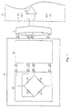
- Fig. 1 illustrates in schematic form the Interconnection of a strain gauge transducer according to the invention or transducer 1 with a common external electronic supply and processing circuit 2.
- the circuit 2 supplies the strain gage transducer 1 via two connection points 4a and 4b with DC. At the same time it receives its output signals via two connection points 8a and 8b and then process it.
- a Strain gauge bridge 10 and an additional circuit 20 integrated.
- the construction of the DMS bridge 10, which essentially consists of the bridge entrances 14a and 14b, the bridge exits 18a and 18b as well the bridge branches connected DMS resistors 15 and their integration into the strain gauge transducer 1 are known. They will therefore be here not described further.
- the additional circuit 20 is made essentially from a modulation amplifier.
- strain gage transducer 1 differs according to a common passive Strain gage transducer, i. Measuring device, the only one DMS bridge has, by its additional circuit 20th
- the external circuit 2 supplies the additional circuit 20 via the connection points 4a and 4b of Measuring transducer 1 with DC voltage. These in turn supplies the strain gauge bridge 10 at the two connection points 24a and 24b with an AC voltage. At the same time it receives their measuring signals the two connection points 28a and 28b.
- the addition circuit 20 processes the measurement signals and outputs them over the two connection points 8a and 8b of Measuring transducer 1 to the external circuit 2 on. There, the measurement signal can first by means of an amplifier 9 reinforced in a conventional manner and then processed. The entire signal exchange between the transducer 1 and the external Circuit 2 is guided via a supply cable 5.
- the transducer according to the invention can be 1 in exactly the same way as a common one passive transducer to a (common) external Supply voltage and signal evaluation circuit 2 connect. User side is so no conversion when switching between passive and inventive transducers required. Externally, no difference is apparent.
- the additional circuit 20 provides an amplified signal at the two connection points 8a and 8b of Measuring transducer 1 ready, e.g. ten times bigger than the output signal of the strain gauge bridge 10 at the connection points 28a and 28b.
- points the transducer 1 so a ten times smaller Supply current, a ten times better weighing resolution or a tenfold overcharge capacity.
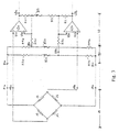
- Fig. 2 shows a preferred circuit diagram for the designed as a modulation amplifier additional circuit 20.
- the modulation amplifier consists essentially from a modulator 30, an AC amplifier 40 and a demodulator 50. Between the demodulator 50 and the signal output terminals 8a and 8b is still a low-pass filter 60 connected.
- the supplied via the connection points 4a and 4b DC voltage is parallel via branch lines 36a and 36b, 46a and 46b as well 56a and 56b respectively at the modulator 30, at the AC amplifier 40 and the demodulator 50 at.
- the modulator 30 essentially includes a square wave generator 32, which from the supply voltage two alternating voltage trains phase-shifted by 180 ° generated.
- the one AC voltage train is input to the one input 14a of the DMS bridge 10 supplied, via a resistor 35a and the one additional circuit output 24a.
- the other AC voltage is - over a Resistor 35b and the other auxiliary circuit output 24b - the other input 14b of the DMS bridge 10 supplied.
- the two outputs 18a and 18b of the DMS bridge 10 are via the two additional circuit inputs 28a and 28b with two signal inputs 44a and 44b of the AC amplifier 40 connected.
- This is essentially a balanced differential amplifier formed, thus contains essentially two symmetrical to an impedance R2 arranged operational amplifier 42a and 42b.
- the (non-negated) inputs 44a and 44b of these two operational amplifiers 42a and 42b form the signal inputs of the AC amplifier 40.
- the two outputs 48a and 48b of the operational amplifiers 42a and 42b are respectively via a resistor R1 to the negated operational amplifier inputs 45a and 45b returned and each other via the series connection: resistance R1 - resistor R2 - resistor R1 connected.
- the two amplifier outputs 48a and 48b with two inputs 54a and 54b of the demodulator 50 connected.
- This consists of FIG. 2 in essentially of four analog switches 52a, 52b and 53a, 53b, which the two inputs 54a and 54b with two outputs 58a and 58b of the demodulator 50 such connect each input 54a and 54b alternately is connected to each output 58a and 58b.
- each demodulator output 58a and 58b with one of two of the four switches 52a, b and 53a, b formed switch pair 52a and 53a and 52b and 53b connected; namely, the output 58a with the Switches 52a and 53a and the output 58b with the Switches 52b and 53b.
- everyone branches Demodulator input 54a and 54b in two branch lines, fed the different switch pairs are such that the four branches and the four switches 52a, b and 53a, b are mutually reversible assigned.
- the ON or OFF switching the four switches 52a, b and 53a, b are of the both rectangular output signals of the modulator 30 controlled, i.
- each of the two modulator output signals clocks at the same time in each of the two Switch pairs 52a, 53a and 52b, 53b exactly one Switch so that the two of the same signal Timed switches 52a, 53b or 53a, 52b alternately open and close and always with each other assume complementary switching states.
- demodulator 50 forms a bridge rectifier, which the connection between his inputs and Outputs cyclically in time with the modulation frequency reversed. This is at the outputs 58a and 58b of the demodulator 50 a (differential) DC voltage whose amplitude coincides with that of the AC voltage at the outputs 48a and 48b of the AC amplifier 40 matches.
- the circuit thus provides a phase sensitive Demodulation of the AC signal in a DC output signal ready.
- the demodulator outputs 58a and 58b are according to Fig. 2 via the simple RC low-pass filter 60 with connected to the outputs 8a and 8b of the transducer 1.
- the low-pass filter 60 suppresses high-frequency Voltages due to not perfect switches and Amplifier circuits may occur. He insists of two series-connected resistors 62a and 62b and a capacitor arranged therebetween 65.
- the output of the low pass filter 60 is passed over the Capacitor 65 tapped.
- the tension on the with the low-pass tap connected outputs 8a and 8b of the transducer 1 is a reinforced, otherwise but exact replica of that DC voltage, which the above-mentioned, common passive Transducer provide: i.
- Measuring transducer which is essentially only a DMS bridge with the Connection points 14a, b and 18a, b and 24a, b and 28a, b have. In this comparison is still to be considered that the two resistors 62a and 62b exactly half the value of the output resistance of the passive transducer should be given.
- the low-pass filter 60 may also be omitted and either the (the external circuit 2 and the transducer 1 connecting) Zuleftungsrade 5 with its capacitive and inductive properties used as a low-pass filter or a low-pass filter be provided in the external circuit 2.
- Fig. 2 is on a used symmetrical differential amplifier 40.
- FIG. 3 shows a resistor network that the added to balanced differential amplifier 40 becomes.
- the resistor network consists essentially from a resistance bridge 80 and three additional ones Resistors R3c, R4c and 87.
- the resistance bridge 80 has the two bridge inputs 84a and 84b and the two bridge outputs 88a and 88b.
- the bridge inputs 84a and 84b are connected to the Inputs 14a and 14b of the DMS bridge 10 connected in parallel.
- the bridge output 88a is above the resistor R4c at the negated input 45a of the operational amplifier 42a; the bridge output 88b via the resistor R3c at the negated input 45b of Operational amplifier 42b.
- the resistance bridge 80 is made up of resistors R3a, b and R4a, b and temperature dependent Resistors 85a, b composed in such a way the resistor R4a has a first bridge branch, the resistor R4b together with the temperature-dependent Resistor 85b a second bridge branch, the resistor R3b has a third bridge branch and the resistor R3a together with the temperature-dependent Resistor 85a a fourth bridge branch form.
- the temperature-dependent resistor 87 is in series connected with the resistor R2 and determined together with the resistors R1 and R2 the gain of the balanced differential amplifier 40th
- the temperature-dependent resistors 85a, b is a temperature-dependent zero offset the strain gauge bridge 10 and the symmetrical Differential amplifier 40 and the temperature-dependent Resistor 87 the temperature dependence the strain gage bridge output and the gain factor of the balanced differential amplifier 40 balance.
Landscapes
- Physics & Mathematics (AREA)
- General Physics & Mathematics (AREA)
- Engineering & Computer Science (AREA)
- Power Engineering (AREA)
- Measurement Of Length, Angles, Or The Like Using Electric Or Magnetic Means (AREA)
- Amplifiers (AREA)
- Measurement Of Force In General (AREA)
- Measuring Fluid Pressure (AREA)
Abstract
Claims (12)
- Capteur à jauges de contrainte (1) dans lequel sont intégrés :a) une partie jauge de contrainte, qui est formée d'une jauge de contrainte au moins, etb) un montage additionnel (20) qui présente un amplificateur (40) intercalé en aval de la partie jauge de contrainte, pour amplifier le signal de sortie de la partie jauge de contrainte,
caractérisé en ce quec) le capteur à jauges de contrainte (1) est aménagé pour une alimentation en tension continue, etd) le circuit additionnel (20) est agencé comme un amplificateur à modulation, qui est essentiellement composé d'un modulateur (30), lequel est intercalé en amont de la partie jauge de contrainte comme fourniture d'alimentation en tension alternative, de l'amplificateur (40) et d'un démodulateur (50). - Capteur à jauges de contrainte (1) conforme à la revendication 1, caractérisé en ce que la partie jauge de contrainte se présente sous forme d'un pont de jauges de contrainte formé de plusieurs jauges de contrainte.
- Capteur à jauges de contrainte (1) conforme à la revendication 1 ou 2, caractérisé en ce quea) le modulateur (30) est un générateur de signal rectangulaire,b) le démodulateur (50) est de manière essentielle constitué d'un redresseur en pont composé de quatre commutateurs tout ou rien (52a, b; 53a, b) ou de deux interrupteurs électroniques à bascule va et vient, etc) le démodulateur (50) et le modulateur (30) sont branchés l'un à l'autre de telle manière que le signal rectangulaire du modulateur (30) synchronise la commutation des quatre commutateurs électroniques tout ou rien (52a, b; 53a, b) ou les deux interrupteurs électroniques à bascule va et vient du démodulateur (50).
- Capteur à jauges de contrainte (1) conforme à l'une quelconque des revendications précédentes, caractérisé en ce que le montage additionnel (20) présente un filtre RC passe-bas (60) branché en aval du démodulateur (50).
- Capteur à jauges de contrainte (1) conforme à l'une quelconque des revendications précédentes, caractérisé en ce que l'amplificateur (40) est, de manière essentielle, un amplificateur différentiel symétrique.
- Capteur à jauges de contrainte (1) conforme à la revendication 5, caractérisé en ce que le câblage des sorties (48a, b) des deux amplificateurs (42a, b) de l'amplificateur différentiel symétrique (40) comporte en outre une résistance (87) qui dépend de la température pour compenser une erreur consécutive au fait que le signal de sortie du capteur à jauges de contraintes et le facteur d'amplification dépendent de la température.
- Capteur à jauges de contrainte (1) conforme à l'une quelconque des revendications 4 à 6, caractérisé en ce que une résistance (35a, b) est branchée en série dans les deux entrées respectives d'alimentation en tension continue (14a, b) du pont de jauges de contrainte (10).
- Capteur à jauges de contrainte (1) conforme à l'une quelconque des revendications précédentes, caractérisé en ce que le capteur à jauges de contrainte (1), muni de la partie à jauges de contrainte ainsi que du circuit additionnel (20) constitue un capteur passif à jauges de contrainte.
- Capteur à jauges de contrainte (1) conforme à la revendication 8, caractérisé en ce qu'il comporte quatre connexions électriques, c'est-à-dire deux pour l'alimentation en tension (4a, 4b) et deux pour le signal de sortie (8a, 8b).
- Capteur à jauges de contrainte (1) conforme à l'une quelconque des revendications précédentes, caractérisé en ce que le circuit additionnel (20) est réalisé selon une structure hybride sur de la céramique.
- Capteur à jauges de contrainte (1) conforme à l'une quelconque des revendications précédentes, caractérisé en ce que le capteur à jauges de contrainte (1) est placé en amont d'un convertisseur analogique-numérique et/ ou d'un microprocesseur.
- Amplificateur à modulation, qui, pour amplifier la sortie d'un montage en pont, est agencé avec des jauges de contrainte d'un capteur à jauges de contrainte (1) conformément à l'une des revendications précédentes, qui consiste de manière essentielle en :a) un modulateur (30) formé d'un générateur de signal rectangulaire (32),b) un amplificateur de tension alternative (40), etc) un démodulateur (50) qui est agencé comme un redresseur en pont composé de l'un parmi quatre interrupteurs électroniques tout ou rien (52a, b ; 53a, b) ou bien de deux interrupteurs électriques à bascule va et vient,
caractérisé en ce qued) l'amplificateur de tension alternative (40) est agencé comme un amplificateur différentiel symétrique, ete) l'entrée de l'amplificateur différentiel symétrique peut être couplée à la sortie du montage en pont et l'entrée du démodulateur peut être couplée à la sortie de l'amplificateur différentiel symétrique et le modulateur est commandé de telle manière que le caractère différentiel du signal de sortie du montage en pont reste conservé.
Applications Claiming Priority (3)
| Application Number | Priority Date | Filing Date | Title |
|---|---|---|---|
| DE4417228A DE4417228A1 (de) | 1994-05-17 | 1994-05-17 | Dehnungsmeßstreifen-Meßanordnung, Verwendung derselben und Modulationsverstärker für derartige Meßanordnungen |
| DE4417228 | 1994-05-17 | ||
| PCT/EP1995/001865 WO1995031701A1 (fr) | 1994-05-17 | 1995-05-17 | Dispositif de mesure a jauges de contrainte, son application et amplificateur de modulation pour un tel dispositif |
Publications (3)
| Publication Number | Publication Date |
|---|---|
| EP0760936A1 EP0760936A1 (fr) | 1997-03-12 |
| EP0760936B1 EP0760936B1 (fr) | 1998-07-29 |
| EP0760936B2 true EP0760936B2 (fr) | 2005-03-16 |
Family
ID=6518269
Family Applications (1)
| Application Number | Title | Priority Date | Filing Date |
|---|---|---|---|
| EP95924202A Expired - Lifetime EP0760936B2 (fr) | 1994-05-17 | 1995-05-17 | Capteur à jauges de contrainte et amplificateur de modulation pour un circuit à pont |
Country Status (7)
| Country | Link |
|---|---|
| US (1) | US5777235A (fr) |
| EP (1) | EP0760936B2 (fr) |
| JP (1) | JP2978248B2 (fr) |
| CN (1) | CN1111725C (fr) |
| AU (1) | AU2880995A (fr) |
| DE (3) | DE4417228A1 (fr) |
| WO (1) | WO1995031701A1 (fr) |
Families Citing this family (38)
| Publication number | Priority date | Publication date | Assignee | Title |
|---|---|---|---|---|
| FR2757942A1 (fr) * | 1996-12-31 | 1998-07-03 | Motorola Semiconducteurs | Ensemble capteur et procede de polarisation d'un capteur travaillant en presence d'humidite |
| DE19722077B4 (de) * | 1997-05-27 | 2006-11-16 | Horiba Automotive Test Systems Gmbh | Trägerfrequenzmeßverfahren |
| JP3862474B2 (ja) * | 2000-05-16 | 2006-12-27 | キヤノン株式会社 | 画像処理装置、画像処理方法、記憶媒体 |
| DE10221628B4 (de) | 2002-05-15 | 2005-06-23 | Sartorius Ag | Kraftmesssystem mit mehreren Kraftmesszellen und mit einer Schaltung zur Errechnung eines Gesamtsignals |
| US6765391B2 (en) | 2002-10-22 | 2004-07-20 | Texas Instruments Incorporated | Low cost asic architecture for safety critical applications monitoring an applied stimulus |
| US7284438B2 (en) * | 2005-11-10 | 2007-10-23 | Honeywell International Inc. | Method and system of providing power to a pressure and temperature sensing element |
| US7525375B2 (en) | 2005-12-20 | 2009-04-28 | Mettler-Toledo Ag | Method of correcting the output signal of an analog amplifier, amplifier module and measuring device |
| EP1801964A1 (fr) * | 2005-12-20 | 2007-06-27 | Mettler-Toledo AG | Procédé destiné à la correction d'un signal de sortie d'amplificateur analogique, module amplificateur et dispositif de mesure |
| US8265769B2 (en) * | 2007-01-31 | 2012-09-11 | Medtronic, Inc. | Chopper-stabilized instrumentation amplifier for wireless telemetry |
| US7385443B1 (en) * | 2007-01-31 | 2008-06-10 | Medtronic, Inc. | Chopper-stabilized instrumentation amplifier |
| US9615744B2 (en) | 2007-01-31 | 2017-04-11 | Medtronic, Inc. | Chopper-stabilized instrumentation amplifier for impedance measurement |
| US7391257B1 (en) * | 2007-01-31 | 2008-06-24 | Medtronic, Inc. | Chopper-stabilized instrumentation amplifier for impedance measurement |
| US8781595B2 (en) | 2007-04-30 | 2014-07-15 | Medtronic, Inc. | Chopper mixer telemetry circuit |
| US8380314B2 (en) | 2007-09-26 | 2013-02-19 | Medtronic, Inc. | Patient directed therapy control |
| US9072870B2 (en) | 2008-01-25 | 2015-07-07 | Medtronic, Inc. | Sleep stage detection |
| US8766720B2 (en) * | 2012-06-29 | 2014-07-01 | Siemens Energy, Inc. | Hybrid load differential amplifier operable in a high temperature environment of a turbine engine |
| US8478402B2 (en) * | 2008-10-31 | 2013-07-02 | Medtronic, Inc. | Determining intercardiac impedance |
| US9770204B2 (en) | 2009-11-11 | 2017-09-26 | Medtronic, Inc. | Deep brain stimulation for sleep and movement disorders |
| US9157822B2 (en) * | 2011-02-01 | 2015-10-13 | Kulite Semiconductor Products, Inc. | Electronic interface for LVDT-type pressure transducers using piezoresistive sensors |
| CN102183286A (zh) * | 2011-03-09 | 2011-09-14 | 苏州钮曼精密机电有限公司 | 载波激励应变式称重系统及其激励方法 |
| CN102519632B (zh) * | 2011-11-02 | 2013-10-23 | 北京金自天正智能控制股份有限公司 | 一种基于压磁效应原理的新型四孔位线圈整体结构测力传感器 |
| JP5967803B2 (ja) * | 2012-02-25 | 2016-08-10 | 株式会社共和電業 | ひずみゲージ式変換器 |
| EP3030941B1 (fr) | 2013-08-06 | 2018-10-31 | Bedrock Automation Platforms Inc. | Module programmable pour des systèmes de commande industriels |
| CN103743505A (zh) * | 2013-12-20 | 2014-04-23 | 广西科技大学 | 一种汽车应变信号的采集方法 |
| CN105277111B (zh) * | 2014-07-04 | 2018-03-16 | 北京强度环境研究所 | 星箭锁紧装置应变监测系统 |
| US9719871B2 (en) * | 2014-08-09 | 2017-08-01 | Google Inc. | Detecting a state of a wearable device |
| US9924904B2 (en) | 2014-09-02 | 2018-03-27 | Medtronic, Inc. | Power-efficient chopper amplifier |
| CH708761A2 (de) * | 2015-03-03 | 2015-04-30 | Tecpharma Licensing Ag | Messbrückenanordnung mit verbesserter Fehlererkennung. |
| US10408861B2 (en) * | 2015-03-04 | 2019-09-10 | Rohde & Schwarz Gmbh & Co. Kg | Circuit for compensating an offset voltage in an amplifier |
| EP3205992B1 (fr) | 2016-02-11 | 2019-06-19 | MOBA - Mobile Automation AG | Commutation electrique, cellule de pesage, dispositif de detection de charge et vehicule comprenant un dispositif de detection de charge |
| JP6489081B2 (ja) * | 2016-08-05 | 2019-03-27 | 株式会社デンソー | センサ装置 |
| DE102018110100B4 (de) * | 2018-04-26 | 2020-06-18 | Minebea Intec GmbH | Galvanisch getrennte, symmetrische Sensorversorgung eines Analog-Digital-Wandlers für asymmetrische Versorgung |
| CN108759652B (zh) * | 2018-05-17 | 2019-06-28 | 大连理工大学 | 一种基于惠斯通全桥原理的曲率测量方法 |
| US11877864B2 (en) * | 2019-05-29 | 2024-01-23 | Measurement Specialties, Inc. | Voltage nulling pressure sensor preamp |
| CN111307257B (zh) * | 2019-11-11 | 2022-07-01 | 北京全路通信信号研究设计院集团有限公司 | 驼峰溜放车辆测重方法及系统 |
| EP3995801B1 (fr) * | 2020-11-10 | 2025-12-24 | Melexis Technologies SA | Système de polarisation et lecture de capteur à pont |
| EP4145099B1 (fr) | 2021-09-02 | 2025-06-11 | Ratier-Figeac SAS | Ensemble de mesure de contrainte |
| CN118150116B (zh) * | 2024-05-11 | 2024-07-09 | 中国空气动力研究与发展中心高速空气动力研究所 | 一种基于双模电桥的应变天平温度漂移修正装置及方法 |
Citations (4)
| Publication number | Priority date | Publication date | Assignee | Title |
|---|---|---|---|---|
| DE2262755A1 (de) † | 1972-12-21 | 1974-07-11 | Siemens Ag | Digitale kompensationseinrichtung |
| DE3330841A1 (de) † | 1983-08-26 | 1985-03-14 | Siemens AG, 1000 Berlin und 8000 München | Auswerteschaltungen fuer passive messgroessenaufnehmer |
| US4966034A (en) † | 1988-04-28 | 1990-10-30 | Schrader Automotive, Inc. | On-board tire pressure indicating system performing temperature-compensated pressure measurement, and pressure measurement circuitry thereof |
| DE4232032A1 (de) † | 1991-09-25 | 1993-04-01 | Siemens Ag | Zweidraht-stromschleifenschaltung fuer messwertaufnehmer |
Family Cites Families (25)
| Publication number | Priority date | Publication date | Assignee | Title |
|---|---|---|---|---|
| US2625036A (en) * | 1946-08-13 | 1953-01-13 | Texas Co | Strain measurement |
| US3224256A (en) * | 1962-05-07 | 1965-12-21 | Tinius Olsen Testing Mach Co | System to retain and indicate maximum reading of a strain gage type indicator |
| US3354703A (en) * | 1963-06-27 | 1967-11-28 | Jr Roger B Russell | Ships strain measuring system |
| US3665756A (en) * | 1965-10-18 | 1972-05-30 | Microdot Inc | Strain gauge temperature compensation system |
| US3617878A (en) * | 1969-04-21 | 1971-11-02 | Blh Electronics | Ac to de high-accuracy low-level voltage measuring system |
| US3657660A (en) * | 1970-07-24 | 1972-04-18 | Bendix Corp | Error detecting and failure indicating system and method in a servo loop |
| US3965429A (en) * | 1972-06-21 | 1976-06-22 | Columbia Research Laboratories, Inc. | Circuitry for use with a transducer which generates a signal corresponding to a physical phenomenon |
| US4059991A (en) * | 1975-08-01 | 1977-11-29 | Dybel William P | Modular constructed load sensing system |
| US3956927A (en) * | 1975-09-29 | 1976-05-18 | Honeywell Inc. | Strain gauge transducer apparatus |
| US4064456A (en) * | 1976-04-09 | 1977-12-20 | The United States Of America As Represented By The Secretary Of The Air Force | Meter box assembly |
| US4155263A (en) * | 1978-02-28 | 1979-05-22 | Eaton Corporation | Multiplexed strain gauge bridge |
| US4213348A (en) * | 1979-08-01 | 1980-07-22 | Medasonics, Inc. | Self-calibrating automatic zeroing strain gauge circuit |
| DE3125133A1 (de) * | 1981-06-26 | 1983-01-13 | Datron-Electronic GmbH, 6109 Mühltal | "verfahren und vorrichtung zur messung von physikalischen groessen, insbesondere gewichten" |
| US4461182A (en) * | 1982-07-23 | 1984-07-24 | Niagara Machine & Tool Works | Load measuring apparatus |
| JPS59168331A (ja) * | 1983-03-15 | 1984-09-22 | Fuji Electric Co Ltd | 圧力変換器 |
| JPS59208429A (ja) * | 1983-05-13 | 1984-11-26 | Tokyo Electric Co Ltd | ロ−ドセル |
| JPS6071964A (ja) * | 1983-09-29 | 1985-04-23 | Nec Corp | 物理量検出回路 |
| US4600347A (en) * | 1984-11-09 | 1986-07-15 | Continental Can Company, Inc. | Double seam tightness monitor |
| US4606205A (en) * | 1984-11-09 | 1986-08-19 | Continental Can Company, Inc. | Applied force monitor for apparatus for forming products from sheet material |
| JPS61209332A (ja) * | 1985-03-13 | 1986-09-17 | Tokyo Electric Co Ltd | 歪センサ− |
| US4815547A (en) * | 1987-11-30 | 1989-03-28 | Toledo Scale Corporation | Load cell |
| GB2221039A (en) * | 1988-07-05 | 1990-01-24 | Peter Adam Reuter | Load cell device with integral data processing/output means |
| FR2670901B1 (fr) * | 1990-11-26 | 1993-05-07 | Precia Sa | Dispositif d'amplification du signal de desequilibre d'un pont de wheatstone, destine a etre incorpore notamment a une balance de haute precision. |
| US5088330A (en) * | 1990-11-29 | 1992-02-18 | Pitney Bowes Inc. | Square wave excitation of a transducer |
| JP3106458U (ja) | 2004-07-08 | 2005-01-06 | 彰則 伊藤 | 連結・切り離し及び折りたたみ収納できるカードケース |
-
1994
- 1994-05-17 DE DE4417228A patent/DE4417228A1/de not_active Withdrawn
-
1995
- 1995-05-17 CN CN95193123A patent/CN1111725C/zh not_active Expired - Lifetime
- 1995-05-17 EP EP95924202A patent/EP0760936B2/fr not_active Expired - Lifetime
- 1995-05-17 AU AU28809/95A patent/AU2880995A/en not_active Abandoned
- 1995-05-17 DE DE29521703U patent/DE29521703U1/de not_active Expired - Lifetime
- 1995-05-17 DE DE59503003T patent/DE59503003D1/de not_active Expired - Lifetime
- 1995-05-17 WO PCT/EP1995/001865 patent/WO1995031701A1/fr not_active Ceased
- 1995-05-17 JP JP7529371A patent/JP2978248B2/ja not_active Expired - Lifetime
-
1996
- 1996-06-07 US US08/665,049 patent/US5777235A/en not_active Expired - Lifetime
Patent Citations (4)
| Publication number | Priority date | Publication date | Assignee | Title |
|---|---|---|---|---|
| DE2262755A1 (de) † | 1972-12-21 | 1974-07-11 | Siemens Ag | Digitale kompensationseinrichtung |
| DE3330841A1 (de) † | 1983-08-26 | 1985-03-14 | Siemens AG, 1000 Berlin und 8000 München | Auswerteschaltungen fuer passive messgroessenaufnehmer |
| US4966034A (en) † | 1988-04-28 | 1990-10-30 | Schrader Automotive, Inc. | On-board tire pressure indicating system performing temperature-compensated pressure measurement, and pressure measurement circuitry thereof |
| DE4232032A1 (de) † | 1991-09-25 | 1993-04-01 | Siemens Ag | Zweidraht-stromschleifenschaltung fuer messwertaufnehmer |
Non-Patent Citations (1)
| Title |
|---|
| "Drucksensoren", G. Pfeifer, R. Werthschützky, VEB Verlag Technik Berlin, 1989, Seite 132-135 † |
Also Published As
| Publication number | Publication date |
|---|---|
| EP0760936A1 (fr) | 1997-03-12 |
| US5777235A (en) | 1998-07-07 |
| AU2880995A (en) | 1995-12-05 |
| EP0760936B1 (fr) | 1998-07-29 |
| CN1111725C (zh) | 2003-06-18 |
| DE4417228A1 (de) | 1995-11-23 |
| CN1148889A (zh) | 1997-04-30 |
| DE29521703U1 (de) | 1998-05-20 |
| JPH10504099A (ja) | 1998-04-14 |
| DE59503003D1 (de) | 1998-09-03 |
| WO1995031701A1 (fr) | 1995-11-23 |
| JP2978248B2 (ja) | 1999-11-15 |
Similar Documents
| Publication | Publication Date | Title |
|---|---|---|
| EP0760936B2 (fr) | Capteur à jauges de contrainte et amplificateur de modulation pour un circuit à pont | |
| DE10160794B4 (de) | Signalverarbeitungseinrichtung für einen Druckschalter od. dgl. | |
| CH657457A5 (de) | Pruefeinrichtung zur bestimmung von schwingungseigenschaften mindestens eines messwertaufnehmers. | |
| DE2104850C3 (de) | Schaltungsanordnung zur Überprüfung des Elektroden-Übergangswiderstandes während der Registrierung von mittels Differenzverstärkern verstärkten bioelektrischen Signalen | |
| EP1377887B1 (fr) | Configuration de circuit et procede permettant d'obtenir une compensation thermique | |
| DE2311184A1 (de) | Messtechnischer detektor | |
| EP2959306B1 (fr) | Appareil de mesure de puissance à étalonnage interne de détecteurs à diodes | |
| DE2115029C3 (de) | Einrichtung zur Temperaturmessung | |
| DE19722077B4 (de) | Trägerfrequenzmeßverfahren | |
| DE69019891T2 (de) | Optischer Transformator. | |
| DE2258690A1 (de) | Impedanzvergleichsschaltung | |
| DE10028486A1 (de) | Sensor für die Kantenposition eines elektrisch leitenden Materials | |
| DE10120983B4 (de) | Meßbrückenschaltung in Vier- oder Mehrleitertechnik mit Ausregelung der Leitungseinflüsse | |
| DE19511353C1 (de) | DMS-Wägeaufnehmer mit Ecklastkorrektur | |
| EP0137896B1 (fr) | Circuit pour compenser les variations du facteur de transfert d'une sonde linéaire de champ magnétique | |
| DE3007426A1 (de) | Schaltungsanordnung mit einem kondensator im rueckkopplungszweig eines operationsverstaerkers | |
| DE2451281C3 (de) | Meßverstärker | |
| DE69315452T2 (de) | Elektronische kapazitive Sensorstangeneinrichtung | |
| DE2915357A1 (de) | Uebertragungseinrichtung fuer von einem messwertgeber abgegebene analoge wechselsignale | |
| DE3326956C2 (de) | Stromdifferenzschaltung zur Messung kleiner Widerstandsänderungen | |
| DE3819370A1 (de) | Vorrichtung zur gleichstrommessung | |
| DE3817371A1 (de) | Differentieller induktiver geber mit digitalausgang | |
| DE2158269B2 (de) | Schaltung zum Umformen von Widerstandswerten in Stromwerte | |
| DE3135409C2 (de) | Meßwertaufnehmer in Brückenschaltung | |
| DE4447293A1 (de) | Verfahren und Vorrichtung zur Bestimmung einer jeweiligen örtlichen Position eines Körpers durch kapazitive Abtastung |
Legal Events
| Date | Code | Title | Description |
|---|---|---|---|
| PUAI | Public reference made under article 153(3) epc to a published international application that has entered the european phase |
Free format text: ORIGINAL CODE: 0009012 |
|
| 17P | Request for examination filed |
Effective date: 19961217 |
|
| AK | Designated contracting states |
Kind code of ref document: A1 Designated state(s): CH DE FR GB IT LI |
|
| GRAG | Despatch of communication of intention to grant |
Free format text: ORIGINAL CODE: EPIDOS AGRA |
|
| 17Q | First examination report despatched |
Effective date: 19970526 |
|
| GRAG | Despatch of communication of intention to grant |
Free format text: ORIGINAL CODE: EPIDOS AGRA |
|
| GRAH | Despatch of communication of intention to grant a patent |
Free format text: ORIGINAL CODE: EPIDOS IGRA |
|
| GRAG | Despatch of communication of intention to grant |
Free format text: ORIGINAL CODE: EPIDOS AGRA |
|
| GRAH | Despatch of communication of intention to grant a patent |
Free format text: ORIGINAL CODE: EPIDOS IGRA |
|
| GRAH | Despatch of communication of intention to grant a patent |
Free format text: ORIGINAL CODE: EPIDOS IGRA |
|
| GRAA | (expected) grant |
Free format text: ORIGINAL CODE: 0009210 |
|
| AK | Designated contracting states |
Kind code of ref document: B1 Designated state(s): CH DE FR GB IT LI |
|
| REG | Reference to a national code |
Ref country code: CH Ref legal event code: NV Representative=s name: R. A. EGLI & CO. PATENTANWAELTE Ref country code: CH Ref legal event code: EP |
|
| GBT | Gb: translation of ep patent filed (gb section 77(6)(a)/1977) |
Effective date: 19980729 |
|
| REF | Corresponds to: |
Ref document number: 59503003 Country of ref document: DE Date of ref document: 19980903 |
|
| ET | Fr: translation filed | ||
| PLBI | Opposition filed |
Free format text: ORIGINAL CODE: 0009260 |
|
| PLBF | Reply of patent proprietor to notice(s) of opposition |
Free format text: ORIGINAL CODE: EPIDOS OBSO |
|
| 26 | Opposition filed |
Opponent name: ENDRESS + HAUSER (DEUTSCHLAND) HOLDING GMBH Effective date: 19990421 |
|
| PLBF | Reply of patent proprietor to notice(s) of opposition |
Free format text: ORIGINAL CODE: EPIDOS OBSO |
|
| PLBF | Reply of patent proprietor to notice(s) of opposition |
Free format text: ORIGINAL CODE: EPIDOS OBSO |
|
| RAP2 | Party data changed (patent owner data changed or rights of a patent transferred) |
Owner name: SPECTRIS AG |
|
| RIN2 | Information on inventor provided after grant (corrected) |
Free format text: SPECTRIS AG |
|
| RAP2 | Party data changed (patent owner data changed or rights of a patent transferred) |
Owner name: HBM WAEGETECHNIK GMBH |
|
| RIN2 | Information on inventor provided after grant (corrected) |
Free format text: HBM WAEGETECHNIK GMBH |
|
| REG | Reference to a national code |
Ref country code: GB Ref legal event code: 732E |
|
| REG | Reference to a national code |
Ref country code: GB Ref legal event code: 732E |
|
| REG | Reference to a national code |
Ref country code: GB Ref legal event code: IF02 |
|
| PLBP | Opposition withdrawn |
Free format text: ORIGINAL CODE: 0009264 |
|
| RIN2 | Information on inventor provided after grant (corrected) |
Inventor name: ALTWEIN, MICHAEL |
|
| PLAY | Examination report in opposition despatched + time limit |
Free format text: ORIGINAL CODE: EPIDOSNORE2 |
|
| PLBC | Reply to examination report in opposition received |
Free format text: ORIGINAL CODE: EPIDOSNORE3 |
|
| PUAH | Patent maintained in amended form |
Free format text: ORIGINAL CODE: 0009272 |
|
| STAA | Information on the status of an ep patent application or granted ep patent |
Free format text: STATUS: PATENT MAINTAINED AS AMENDED |
|
| 27A | Patent maintained in amended form |
Effective date: 20050316 |
|
| AK | Designated contracting states |
Kind code of ref document: B2 Designated state(s): CH DE FR GB IT LI |
|
| GBTA | Gb: translation of amended ep patent filed (gb section 77(6)(b)/1977) | ||
| REG | Reference to a national code |
Ref country code: CH Ref legal event code: AEN Free format text: AUFRECHTERHALTUNG DES PATENTES IN GEAENDERTER FORM |
|
| ET3 | Fr: translation filed ** decision concerning opposition | ||
| PGFP | Annual fee paid to national office [announced via postgrant information from national office to epo] |
Ref country code: GB Payment date: 20140528 Year of fee payment: 20 |
|
| PGFP | Annual fee paid to national office [announced via postgrant information from national office to epo] |
Ref country code: IT Payment date: 20140528 Year of fee payment: 20 Ref country code: CH Payment date: 20140620 Year of fee payment: 20 |
|
| PGFP | Annual fee paid to national office [announced via postgrant information from national office to epo] |
Ref country code: DE Payment date: 20140820 Year of fee payment: 20 |
|
| PGFP | Annual fee paid to national office [announced via postgrant information from national office to epo] |
Ref country code: FR Payment date: 20140528 Year of fee payment: 20 |
|
| REG | Reference to a national code |
Ref country code: DE Ref legal event code: R071 Ref document number: 59503003 Country of ref document: DE |
|
| REG | Reference to a national code |
Ref country code: CH Ref legal event code: PL |
|
| REG | Reference to a national code |
Ref country code: GB Ref legal event code: PE20 Expiry date: 20150516 |
|
| PG25 | Lapsed in a contracting state [announced via postgrant information from national office to epo] |
Ref country code: GB Free format text: LAPSE BECAUSE OF EXPIRATION OF PROTECTION Effective date: 20150516 |