EP0761430A1 - Appareil pour la fabrication de stencils thermosensibles - Google Patents
Appareil pour la fabrication de stencils thermosensibles Download PDFInfo
- Publication number
- EP0761430A1 EP0761430A1 EP96114302A EP96114302A EP0761430A1 EP 0761430 A1 EP0761430 A1 EP 0761430A1 EP 96114302 A EP96114302 A EP 96114302A EP 96114302 A EP96114302 A EP 96114302A EP 0761430 A1 EP0761430 A1 EP 0761430A1
- Authority
- EP
- European Patent Office
- Prior art keywords
- platen
- screen fabric
- screen
- width
- thermal head
- Prior art date
- Legal status (The legal status is an assumption and is not a legal conclusion. Google has not performed a legal analysis and makes no representation as to the accuracy of the status listed.)
- Granted
Links
- 239000004744 fabric Substances 0.000 claims abstract description 69
- 230000020169 heat generation Effects 0.000 claims 1
- 238000010438 heat treatment Methods 0.000 claims 1
- 238000010586 diagram Methods 0.000 description 8
- 230000004048 modification Effects 0.000 description 2
- 238000012986 modification Methods 0.000 description 2
- 239000000853 adhesive Substances 0.000 description 1
- 230000001070 adhesive effect Effects 0.000 description 1
- 239000000839 emulsion Substances 0.000 description 1
Images



Classifications
-
- B—PERFORMING OPERATIONS; TRANSPORTING
- B41—PRINTING; LINING MACHINES; TYPEWRITERS; STAMPS
- B41C—PROCESSES FOR THE MANUFACTURE OR REPRODUCTION OF PRINTING SURFACES
- B41C1/00—Forme preparation
- B41C1/14—Forme preparation for stencil-printing or silk-screen printing
- B41C1/144—Forme preparation for stencil-printing or silk-screen printing by perforation using a thermal head
Definitions
- This invention relates to a heat-sensitive type mimeographic-screen forming apparatus which drives a thermal head to selectively heat a screen fabric which has been spread on a screen fabric frame, to form a mimeographic screen as a stencil.
- a heat-sensitive type mimeographic-screen forming apparatus is well known in the art which employs a thermal head which is brought into contact with a screen fabric spread on a screen fabric frame.
- the screen fabric frame is for instance a rectangular frame on which a screen fabric is spread tight.
- a screen fabric as illustrated in Fig. 13 is generally used. That is, the heat-sensitive fabric (thermal screen) is obtained by making a heat-sensitive film 110 adhere to a screen fabric 100 with an adhesive 120, and the heat-sensitive screen fabric is then merely spread on the screen frame as it is for use. That is, the heat-sensitive screen fabric is imaginably in a state where emulsion has been coated on the fabric.
- the conventional apparatus which forms the mimeographic-screen from the screen fabric spread on the frame, it has a flat plate of rubber and a serial type thermal head which is relatively small in effective width.
- the flat plate of rubber is fitted in the frame to support the screen fabric, thus being used as a platen.
- the serial type thermal head is brought into contact with the screen fabric spread on the frame to form the mimeographic-screen.
- the frame obstructs the setting of the platen on the reverse side of the screen fabric.
- the frame obstructs the setting of the thermal head.
- an object of the invention is to eliminate the above-described difficulties accompanying a conventional heat-sensitive type mimeographic screen forming apparatus.
- a thermal head is provided the length of which corresponds to the width of the widest among a plurality of screen fabric frames to be used, and its platen is replaced with another one or changed in width depending on the width of a screen fabric frame to be used, and the thermal head and the platen are moved with respect to the screen fabric in a synchronization mode.
- the thermal head and the platen are moved in a synchronization mode, and the platen is replaceable with another one or changed in width according to the width of a screen fabric frame to be used. This feature relieves the limitation to the use of screen fabrics. Furthermore, since the long thermal head is used, the mimeographic screen forming speed is increased as much.
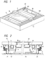
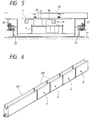
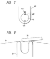
- FIGS. 1 to 12 show the embodiments of the invention. More specifically, FIGS. 1 to 4 show an example of a heat-sensitive type mimeographic screen forming apparatus according to a first embodiment of the invention; FIGS. 5 to 8 show another example of the heat-sensitive type mimeographic screen forming apparatus according to a second embodiment of the invention; FIGS. 9 and 10 show still another example of the heat-sensitive type mimeographic screen forming apparatus according to a third embodiment of the invention; and FIGS. 11 and 12 show yet still another example of the heat-sensitive type mimeographic screen forming apparatus according to a fourth embodiment of the invention.
- reference numeral 1 designates the heat-sensitive type mimeographic screen forming apparatus; 2, a mimeographic-screen-forming-member moving mechanism; 3, a screen fabric frame; and 4, a platen holding mechanism.
- FIG. 1 is a perspective view showing an external appearance of the heat-sensitive type mimeographic screen forming apparatus.
- the screen fabric frame 3 is fixedly positioned by a screen fabric frame holding mechanism 32.
- a thermal head 24 (FIG. 2) for forming a mimeographic screen is mounted in the mimeographic-screen-forming-member moving mechanism 2 and urged downwardly by springs.
- the mechanism 2 is moved longitudinally of the screen fabric 31 spread on the screen fabric frame 3.
- a printing image holding device (not shown) outputs an image signal, which is applied to the thermal head 24 so as to form a mimeographic-screen.
- the mimeographic-screen-forming-member moving mechanism 2 has a pair of slide members 22 which are guided by a pair of guide rails 21 mounted on the base stand 11 of the body of the apparatus.
- a head holding member 23 holding the thermal head 24, and the platen holding mechanism 4 are coupled to the slide members 22.
- the slide members 22 are coupled to electric motors (not shown), respectively, and in response to a movement instruction from the printing image holding device they are moved longitudinally of the screen fabric 31 in synchronization with each other.
- the platen holding mechanism 4 comprises: a platen 41; a gear mechanism 42 for moving up and down the platen 41; a swinging lever 43 coupled to the gear mechanism 42; and a slide guide 44.
- the platen 42 is rotatably supported by the platen holding mechanism 4 so that it is rotated when moved together with the thermal head 24 with the screen fabric 31 held between them under a predetermined pressure.
- the platen 41 is coupled to the swinging lever 43 through the gear mechanism 42.
- the apparatus is so designed that, for instance when it is required to replace the screen fabric 3 with a new one, the platen 41 of the platen holding mechanism 4 can be set at a lower position as shown in FIG. 3 by operating the swinging lever 43.
- the platen 41 is supported by a first holding section 411 and a second holding section 412.
- the holding section 412 on the right side is so designed that it is slidable in the direction of arrangement of the thermal head 24 whereby in the case of using another screen fabric frame (3) smaller in width than the present screen fabric frame 3, the platen 41 may be replaced with a platen (41) smaller in width.
- a movable-side screen fabric holding mechanism 322 is provided slidably along a guide groove 33 as shown in FIG. 4; that is, this holding mechanism 322 is slid according to the width of the new screen fabric frame 3.
- the second embodiment is different from the above-described first embodiment in the structure of its platen 41.
- the platen 41 is made up of one stationary platen unit 411 relatively larger in width, and a plurality of movable platen units 412 which are each smaller in width than the stationary platen unit 411 and arranged in alignment with the latter 411.
- Those platen units 411 and 412 have U-shaped grooves in the upper end faces, respectively.
- the movable platen units 412 have each a rise position and a fall position. That is, as shown in FIG. 5, the movable platen units are selectively set at the rise positions and/or at the fall positions, thereby to adjust the width of the platen 41 as a whole.
- Each of the movable platen units 412 has an engaging key 413, and is fitted on a platen holding shaft 40 which has two engaging grooves 401 and 402 in correspondence to the rise position and the fall position of the movable platen unit 412. Hence, as the movable platen unit 412 is turned, it is set at the rise position or the fall position.
- the third embodiment of the invention is as shown in FIGS. 9 and 10.
- the third embodiment is different from the above-described first and second embodiment in that its platen 41 is supported by a pair of platen supporting rollers 42 as shown in FIG. 10.
- This arrangement is advantageous in that, when the platen 41 is replaced with a new one which is different in width from the platen 41, the new platen can be readily centered (so that it is correctly brought into contact with the heat generating part of the thermal head).
- the fourth embodiment is different from the above-described first through third embodiment in that, as shown in FIG. 12, a platen holding mechanism 4 is provided which supports three platens 41 different in length from one another (hereinafter referred to as "a platen assembly 41", when applicable).
- the platen holding mechanism 4 is rotatably provided so that those three platens 41 are positioned at their operating positions, respectively.
- the platen 41 pushes the screen fabric 31 upwardly which is spread on the screen fabric frame 3, so that the top portion of the screen fabric 31 thus pushed upwardly is brought into contact with the heat generating part of the thermal head 24.
- the apparatus thus designed can employ a thermal head which is long enough to cover the whole screen fabric frame.
- the heat-sensitive type mimeographic screen forming apparatus of the invention employs the long thermal head to form a mimeographic screen according to the line printing system. Hence, with the apparatus, the mimeographic-screen high in quality having no breaks of an image nor joints of images can be obtained. Furthermore, the apparatus is high in mimeographic screen forming speed. Moreover, in the apparatus, when necessary, the platen may be replaced or changed in width according to the width of a screen fabric frame to be used. Hence, with the apparatus of the invention, screen fabric frames different in width may be used to form mimeographic screens.
- the screen fabric frame may be moved.
Landscapes
- Engineering & Computer Science (AREA)
- Manufacturing & Machinery (AREA)
- Manufacture Or Reproduction Of Printing Formes (AREA)
- Treatment Of Fiber Materials (AREA)
- Electronic Switches (AREA)
Applications Claiming Priority (3)
| Application Number | Priority Date | Filing Date | Title |
|---|---|---|---|
| JP7255574A JPH0970940A (ja) | 1995-09-07 | 1995-09-07 | 感熱製版装置 |
| JP25557495 | 1995-09-07 | ||
| JP255574/95 | 1995-09-07 |
Publications (2)
| Publication Number | Publication Date |
|---|---|
| EP0761430A1 true EP0761430A1 (fr) | 1997-03-12 |
| EP0761430B1 EP0761430B1 (fr) | 1999-12-08 |
Family
ID=17280614
Family Applications (1)
| Application Number | Title | Priority Date | Filing Date |
|---|---|---|---|
| EP96114302A Expired - Lifetime EP0761430B1 (fr) | 1995-09-07 | 1996-09-06 | Appareil pour la fabrication de stencils thermosensibles |
Country Status (5)
| Country | Link |
|---|---|
| US (1) | US5701816A (fr) |
| EP (1) | EP0761430B1 (fr) |
| JP (1) | JPH0970940A (fr) |
| CN (1) | CN1083769C (fr) |
| DE (1) | DE69605500T2 (fr) |
Families Citing this family (6)
| Publication number | Priority date | Publication date | Assignee | Title |
|---|---|---|---|---|
| CN1074991C (zh) * | 1997-12-01 | 2001-11-21 | 杜也兵 | 热敏版纸的打印及挂版方法 |
| US6321438B1 (en) * | 1998-05-01 | 2001-11-27 | Scimed Life Systems, Inc. | Method of applying a matching layer to a transducer |
| JP2007069385A (ja) * | 2005-09-05 | 2007-03-22 | Shigeharu Mori | 孔版スクリーン製版装置 |
| JP6396170B2 (ja) | 2014-10-23 | 2018-09-26 | 理想科学工業株式会社 | 製版装置 |
| CN111703195B (zh) * | 2020-06-28 | 2022-02-18 | 河南沃达丰数码科技有限公司 | 一种网版打印机 |
| CN113524877A (zh) * | 2021-08-18 | 2021-10-22 | 曲阜市玉樵夫科技有限公司 | 一种丝网制版机打印组件及其控制方法 |
Citations (2)
| Publication number | Priority date | Publication date | Assignee | Title |
|---|---|---|---|---|
| US3528335A (en) * | 1968-04-12 | 1970-09-15 | Diagraph Bradley Ind Inc | Stencil cutting apparatus |
| WO1994021463A1 (fr) * | 1993-03-17 | 1994-09-29 | Daisen Co., Ltd. | Appareil de realisation de plaques de forme pour serigraphie |
Family Cites Families (1)
| Publication number | Priority date | Publication date | Assignee | Title |
|---|---|---|---|---|
| JP2638390B2 (ja) * | 1992-05-27 | 1997-08-06 | ブラザー工業株式会社 | 感熱製版装置 |
-
1995
- 1995-09-07 JP JP7255574A patent/JPH0970940A/ja active Pending
-
1996
- 1996-09-05 US US08/706,569 patent/US5701816A/en not_active Expired - Fee Related
- 1996-09-06 DE DE69605500T patent/DE69605500T2/de not_active Expired - Fee Related
- 1996-09-06 EP EP96114302A patent/EP0761430B1/fr not_active Expired - Lifetime
- 1996-09-06 CN CN96109666A patent/CN1083769C/zh not_active Expired - Fee Related
Patent Citations (3)
| Publication number | Priority date | Publication date | Assignee | Title |
|---|---|---|---|---|
| US3528335A (en) * | 1968-04-12 | 1970-09-15 | Diagraph Bradley Ind Inc | Stencil cutting apparatus |
| WO1994021463A1 (fr) * | 1993-03-17 | 1994-09-29 | Daisen Co., Ltd. | Appareil de realisation de plaques de forme pour serigraphie |
| EP0689934A1 (fr) * | 1993-03-17 | 1996-01-03 | Daisen Co., Ltd. | Appareil de realisation de plaques de forme pour serigraphie |
Also Published As
| Publication number | Publication date |
|---|---|
| CN1083769C (zh) | 2002-05-01 |
| JPH0970940A (ja) | 1997-03-18 |
| DE69605500D1 (de) | 2000-01-13 |
| CN1160636A (zh) | 1997-10-01 |
| EP0761430B1 (fr) | 1999-12-08 |
| DE69605500T2 (de) | 2000-05-04 |
| US5701816A (en) | 1997-12-30 |
Similar Documents
| Publication | Publication Date | Title |
|---|---|---|
| US5520109A (en) | Printing apparatus for continuous rotary printing, in particular suitable for high speed and intermittent printing | |
| JPH1142811A (ja) | レーザプリンタ | |
| EP0761430B1 (fr) | Appareil pour la fabrication de stencils thermosensibles | |
| CA2151755A1 (fr) | Imprimante d'index a commande d'exposition | |
| JP2541457Y2 (ja) | 印字装置 | |
| US4769678A (en) | Photograph printing apparatus | |
| CN217555364U (zh) | 一种印刷机的可调节支架 | |
| US5317968A (en) | Plate cocking apparatus for sheet-fed printing press | |
| US20080079957A1 (en) | Multifunction peripheral | |
| JP2000198180A (ja) | スクリ―ン印刷装置 | |
| JP2666098B2 (ja) | 枚葉式印刷機の刷版ひねり調整装置 | |
| JPH0270452A (ja) | サーマルヘッド押付条件設定装置を有する熱転写式プリンタ | |
| US4188114A (en) | Microfiche scanner module | |
| US5454319A (en) | Printing method and apparatus | |
| CN119408297B (zh) | 一种基于多套色叠加的3d效果图案印刷方法 | |
| JP3015681B2 (ja) | プリンタ | |
| JPH0120832B2 (fr) | ||
| JPH0221712B2 (fr) | ||
| JP2613431B2 (ja) | シリアル記録装置 | |
| JPH0535274U (ja) | 熱転写装置 | |
| EP1097822B1 (fr) | Machine d'impression au pochoir | |
| JPH04232058A (ja) | クリーニング装置 | |
| JP2613433B2 (ja) | シリアル記録装置 | |
| KR930009679B1 (ko) | 칼라 비디오 프린터의 필름지 초기 로딩장치 | |
| JPH0970941A (ja) | 感熱製版装置 |
Legal Events
| Date | Code | Title | Description |
|---|---|---|---|
| PUAI | Public reference made under article 153(3) epc to a published international application that has entered the european phase |
Free format text: ORIGINAL CODE: 0009012 |
|
| AK | Designated contracting states |
Kind code of ref document: A1 Designated state(s): DE FR GB |
|
| 17P | Request for examination filed |
Effective date: 19970527 |
|
| GRAG | Despatch of communication of intention to grant |
Free format text: ORIGINAL CODE: EPIDOS AGRA |
|
| 17Q | First examination report despatched |
Effective date: 19980925 |
|
| GRAG | Despatch of communication of intention to grant |
Free format text: ORIGINAL CODE: EPIDOS AGRA |
|
| GRAG | Despatch of communication of intention to grant |
Free format text: ORIGINAL CODE: EPIDOS AGRA |
|
| GRAH | Despatch of communication of intention to grant a patent |
Free format text: ORIGINAL CODE: EPIDOS IGRA |
|
| GRAH | Despatch of communication of intention to grant a patent |
Free format text: ORIGINAL CODE: EPIDOS IGRA |
|
| GRAA | (expected) grant |
Free format text: ORIGINAL CODE: 0009210 |
|
| AK | Designated contracting states |
Kind code of ref document: B1 Designated state(s): DE FR GB |
|
| REF | Corresponds to: |
Ref document number: 69605500 Country of ref document: DE Date of ref document: 20000113 |
|
| ET | Fr: translation filed | ||
| PLBE | No opposition filed within time limit |
Free format text: ORIGINAL CODE: 0009261 |
|
| STAA | Information on the status of an ep patent application or granted ep patent |
Free format text: STATUS: NO OPPOSITION FILED WITHIN TIME LIMIT |
|
| 26N | No opposition filed | ||
| REG | Reference to a national code |
Ref country code: GB Ref legal event code: IF02 |
|
| PGFP | Annual fee paid to national office [announced via postgrant information from national office to epo] |
Ref country code: GB Payment date: 20030903 Year of fee payment: 8 |
|
| PGFP | Annual fee paid to national office [announced via postgrant information from national office to epo] |
Ref country code: FR Payment date: 20030909 Year of fee payment: 8 |
|
| PGFP | Annual fee paid to national office [announced via postgrant information from national office to epo] |
Ref country code: DE Payment date: 20030918 Year of fee payment: 8 |
|
| PG25 | Lapsed in a contracting state [announced via postgrant information from national office to epo] |
Ref country code: GB Free format text: LAPSE BECAUSE OF NON-PAYMENT OF DUE FEES Effective date: 20040906 |
|
| PG25 | Lapsed in a contracting state [announced via postgrant information from national office to epo] |
Ref country code: DE Free format text: LAPSE BECAUSE OF NON-PAYMENT OF DUE FEES Effective date: 20050401 |
|
| GBPC | Gb: european patent ceased through non-payment of renewal fee |
Effective date: 20040906 |
|
| PG25 | Lapsed in a contracting state [announced via postgrant information from national office to epo] |
Ref country code: FR Free format text: LAPSE BECAUSE OF NON-PAYMENT OF DUE FEES Effective date: 20050531 |
|
| REG | Reference to a national code |
Ref country code: FR Ref legal event code: ST |