EP0761536A2 - System und Verfahren zum Einfüllen von festen Gegenständen - Google Patents
System und Verfahren zum Einfüllen von festen Gegenständen Download PDFInfo
- Publication number
- EP0761536A2 EP0761536A2 EP96306370A EP96306370A EP0761536A2 EP 0761536 A2 EP0761536 A2 EP 0761536A2 EP 96306370 A EP96306370 A EP 96306370A EP 96306370 A EP96306370 A EP 96306370A EP 0761536 A2 EP0761536 A2 EP 0761536A2
- Authority
- EP
- European Patent Office
- Prior art keywords
- solids
- filling
- tubular
- sack
- film
- Prior art date
- Legal status (The legal status is an assumption and is not a legal conclusion. Google has not performed a legal analysis and makes no representation as to the accuracy of the status listed.)
- Granted
Links
Images




Classifications
-
- B—PERFORMING OPERATIONS; TRANSPORTING
- B65—CONVEYING; PACKING; STORING; HANDLING THIN OR FILAMENTARY MATERIAL
- B65B—MACHINES, APPARATUS OR DEVICES FOR, OR METHODS OF, PACKAGING ARTICLES OR MATERIALS; UNPACKING
- B65B9/00—Enclosing successive articles, or quantities of material, e.g. liquids or semiliquids, in flat, folded, or tubular webs of flexible sheet material; Subdividing filled flexible tubes to form packages
- B65B9/10—Enclosing successive articles, or quantities of material, in preformed tubular webs, or in webs formed into tubes around filling nozzles, e.g. extruded tubular webs
- B65B9/20—Enclosing successive articles, or quantities of material, in preformed tubular webs, or in webs formed into tubes around filling nozzles, e.g. extruded tubular webs the webs being formed into tubes in situ around the filling nozzles
-
- B—PERFORMING OPERATIONS; TRANSPORTING
- B65—CONVEYING; PACKING; STORING; HANDLING THIN OR FILAMENTARY MATERIAL
- B65B—MACHINES, APPARATUS OR DEVICES FOR, OR METHODS OF, PACKAGING ARTICLES OR MATERIALS; UNPACKING
- B65B9/00—Enclosing successive articles, or quantities of material, e.g. liquids or semiliquids, in flat, folded, or tubular webs of flexible sheet material; Subdividing filled flexible tubes to form packages
- B65B9/10—Enclosing successive articles, or quantities of material, in preformed tubular webs, or in webs formed into tubes around filling nozzles, e.g. extruded tubular webs
- B65B9/20—Enclosing successive articles, or quantities of material, in preformed tubular webs, or in webs formed into tubes around filling nozzles, e.g. extruded tubular webs the webs being formed into tubes in situ around the filling nozzles
- B65B9/2035—Tube guiding means
-
- B—PERFORMING OPERATIONS; TRANSPORTING
- B65—CONVEYING; PACKING; STORING; HANDLING THIN OR FILAMENTARY MATERIAL
- B65B—MACHINES, APPARATUS OR DEVICES FOR, OR METHODS OF, PACKAGING ARTICLES OR MATERIALS; UNPACKING
- B65B9/00—Enclosing successive articles, or quantities of material, e.g. liquids or semiliquids, in flat, folded, or tubular webs of flexible sheet material; Subdividing filled flexible tubes to form packages
- B65B9/10—Enclosing successive articles, or quantities of material, in preformed tubular webs, or in webs formed into tubes around filling nozzles, e.g. extruded tubular webs
- B65B9/20—Enclosing successive articles, or quantities of material, in preformed tubular webs, or in webs formed into tubes around filling nozzles, e.g. extruded tubular webs the webs being formed into tubes in situ around the filling nozzles
- B65B9/213—Enclosing successive articles, or quantities of material, in preformed tubular webs, or in webs formed into tubes around filling nozzles, e.g. extruded tubular webs the webs being formed into tubes in situ around the filling nozzles the web having intermittent motion
Definitions
- the present invention relates to a filling with solids system and a filling with solids method using this system, and in particular, it relates to the filling with solids system and the filling with solids method using this system which are capable of preventing a blocking caused by solids.
- a box-type packing sack whose bottom flat portion allows the entire sack to be stood erect, is used due to the convenience with which it can be exhibited at stores.
- the manufacturing process of such a configuration of a sack can be mainly divided into a sack forming process and a filling process where a completed sack is filled with snack food.
- a solid filling system is disclosed in, for instance, Japanese Patent Laid-Open Publication HEI6-99917 which utilizes a tubular mandrel for forming a sheet like film into a sack, while at the same time the resultant sacks are continously filled with solids.
- a sheet like film is wound around an outer peripheral surface of the tubular mandrel which has a predetermined longitudinal length, and the opposite ends of the film are sealed by a back sealer which extends longitudinally along the outer surface of the tubular mandrel in such a way that the sheet like film is formed into a tubular film. Then the tubular film is sealed laterally by means of a lateral sealer provided below the lower end opening of a tubular mandrel so that the tubular film is formed into a film in the form of a sack.
- the solids drops freely from the upper end opening of the tubular mandrel through a filling passage defined by a hollow portion of the tubular mandrel into a film formed as a sack and then the filled film formed as a sack is forwarded in the longitudinal direction of the tubular mandrel by a film forwarding means, similar to the back sealer, which extends longitudinally along the outer surface of the tubular mandrel.
- the filling with solids system is so configured that the respective film formed as sacks can be filled with solids continuously by repeating the above-described processes.
- Utilizing the profile and the hollow portion of the tubular mandrel indeed allows a sack forming process and a filling process to proceed in an overlapping manner in an assembly line, thereby causing production efficiency to be ensured.
- solids can cause the filling passage of the tubular mandrel to be blocked upon the solids being charged therein, thereby causing making it impossible to fill the sack with solids depending on the amount of solids sack being filled with per unit time, the cross sectional area of the tubular mandrel and the characteristics of the solids, in particular, the frictional characteristic of the inner face of the tubular mandrel.
- a layer of solids may be formed at a certain position of the tubular mandrel in its longitudinal direction at a certain moment. with some solids being supported by the inner surface of the shape retained tubular mandrel, and as a result, the communication through the layer can be blocked so that the solids cannnot pass continuously through the filling passage into the film formed as a sack.
- the tubular mandrel since it is necessary to utilize the peripheral edge of the tubular mandrel, which defines a lower end opening therein, as a mold for forming a bottom surface of the sack when such a sack is sealed by the above-described lateral sealer, it is required that the lateral sealer be disposed immediately below the lower end opening of the tubular mandrel.
- the tubular mandrel extends from the bottom portion of the film formed as a sack, which bottom portion has been formed by sealing the film to even more increase the possibility of the blocking of the filling passage of the tubular mandrel.
- the amount of solids in the respective films formed as sacks may vary due to the resultant disorder caused by such a complex arrangement timing, or the solids can become sandwiched between the sides of the pressed tubular film at that portion where they are sealed together to form the sack, both of which events can cause reduction of production efficiency.
- the tubular mandrel the shorter the longitudinal length of the tubular mandrel becomes, the lower the possibility of the occurrence of the blocking becomes.
- the performing of the back sealing process and the tubular film forwarding process along with the sack forming process and the filling process is normally required, and thus, due to the nature of the whole process, the back sealing means and the tubular film forwarding means have to be arranged to be at a certain position between the upper end opening of the tubular mandrel and the lower end opening thereof. Accordingly, the tubular mandrel must have a minimum longitudinal length in order to accomplish the sack forming process and the filling process in an overlapping manner.
- the object of the present invention is to provide a filling with solids system which is capable of securely overcoming the inability of filling with solids by removing the blocking by the solids, which blocking occurs during the filling process. while at the same time enabling the sack forming process and the filling process to proceed in an overlapping manner.
- Another object of the present invention is to provide a filling with solids system and a filling with solids method which are capable of controlling the continuous filling of the respective films formed as a sack with solids so that the amounts they are filled with are kept substantially constant, or preventing solids from being sandwiched between the opposite portions of the pressed tubular films at that portion where they are sealed together.
- Still another object of the present invention is to provide a filling with solids system which is capable of removing the blocking solids in a suitable manner depending on the type of solids, the amount of solids the sack formed film is being filled with, etc. without needing to convert the existing filling with solids system.
- the blocking solids may occur in such a way that the solids overlap one another in a three dimensional manner at a certain position of the filling passage and then cover the entire cross sectional area thereof to make it impossible to fill the filling passage with solids.
- openings in which the solids are protruded which extends longitudinally are provided at the periphreral surface of the tubular mandrel, some solids are retained in such a way that they protrude through the openings to contact the inner face of the tubular film.
- the wound tubular film moves longitudinally relative to the tubular mandrel and then the solids, which are retained by contacting the inner face of the tubular film, are dragged in the same direction by the moving tubular film.
- the tubular film which is forwarded from the lower end opening of the tubular mandrel, is formed into a sack configuration by means of the sack forming means, the open end of the sack facing in the direction of the upper end opening, and then the film formed as a sack is filled with solids which enter the filling passage via the upper end opening, so that the solids are deposited at the bottom portion of the sack film formed at a certain forward Position from the lower end opening.
- the solids are deposited up to a height higher than the level of the lower end opening, while at the same time they cover the whole cross sectional area of the tubular mandrel, and as a result, the blocking may occur at a certain position of the tubular mandrel depending on the amount of solids a sack is being filled with per unit time, the cross sectional area of the tubular mandrel and the characteristics, the size and the shape of the solids.
- the solids near the inner face of the tubular mandrel protrude from openings, which openings are so formed at an outer surface of the tubular mandrel as to be cut away over a certain length in a backward direction from the end edge defining the lower end opening.
- the solids contact the inner face of the tubular film wound around the outer peripheral surface of the tubular mandrel to be retained thereby. Then, after the tubular film is forwarded longitudinally from the lower end opening by the tubular film forwarding means, similar to the case of the first aspect of the invention, the blocking solids are collapsed, so that the inability of filling with solids can be securely overcome.
- the blocking solids is collapsed during the process of forwarding one film formed as a sack, so that the one film formed as a sack is always unfailingly filled with a certain amount of solids by the time the next tubular film is formed into a sack.
- the amounts of solids the respective films formed as sacks are filled with can be kept substantially constant while at the same time, the solids can be prevented from being sandwiched between the opposite portions of the pressed tubular film, thus enabling the respective films formed as sacks to be filled with solids continuously, whereby production efficiency can be enusured.
- the blocking caused by the solids can be securely prevented in such a way that the size, the shape, etc. of a notch in which solids are protruded of the tube for removing the blocking, which notch extends backwardly from the peripheral edge of the tube's tip opening, may be appropriately selected depending on the type of solids, the amount of solids which a sack is being filled with, etc. without the need to convert an existing filling with solids system .
- Figure 1 is a schematic perspective view of a filling with solids system of the preferred embodiment of the present invention.
- Figure 2 is a perspective view of a tube for removing the blocking solids.
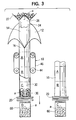
- Figure 3 is a schematic view of a filling with solids method of the preferred embodiment of the present invention.
- Figure 4 is a cross sectional view showing the blocking solids.
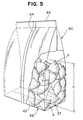
- Figure 5 is a schematic perspective view of a box type sack in a self-standing configuration completed by the filling with solids system of the preferred embodiment of the Present invention.
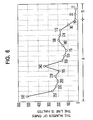
- Figure 6 is a graph showing daily changes in the number of times the line is halted in a case where the filling with solids system of the preferred embodiment of the present invention is used.
- Figure 7 is a graph showing hourly changes in the filling with solids amounts in a case where the filling with solids system of the preferred embodiment of the present invention is used.
- a filling with solids system 10 schematically comprises a tubular mandrel 14 for forming a sheet like film 12 made of polyethylene, etc. into a tubular form, a tubular film forwarding means 18 for forwarding the resultant tubular film 16 in the longitudinal direction, a sack forming means 20 for forming the tubular film 16 into a sack form, and a back sealer 22 for sealing the back portion of the sheet like film 12 .
- the tubular mandrel 14 which is of a conventional type, consists of a longitudinally extending cylinder which has a uniform circular cross section over its entire length.
- a filling passage 24 for solids is defined in the interior of the tubular mandrel 14.
- a metering hopper 27 is provided at an upper end opening 26 of the mandrel 14 so that a quantity of metered solids drops freely from the upper end opening 26 through the filling passage 24 and then is discharged through a lower end opening 28 of the mandrel 14 to be introduced into the tubular film 16.
- the metering hopper 27, which is of a conventional type, is so configured that solids are fed from the upper end opening 26 into the tubular mandrel 14 with some of the solids covering the entire cross sectional area of the tubular mandrel 14.
- a tube 30 for removing blocking solids fits into the lower end opening 28, as described below.
- the tube 30 for removing blocking solids extends a predetermined length in conformity with the profile of the tubular mandrel 14. Accordingly, the interior of the tube 30 is adapted to communicate with the filling passage 24.
- the outer peripheral length of the tube 30 for removing blocking solids is set to be shorter than that of the tubular mandrel 14 so that the tubular film 16 is prevented from being stopped by the outer surface of the tube 30 for removing blocking solids when the tubular film 16 is forwarded by a tubular film forwarding means 18, which will be described below.
- the tube 30 includes four substantially reversed U-shaped notches 40 ( Only two of them are shown in Figure 2) in which solids protrude, each of which extends backwardly and longitudinally from a tip peripheral edge 34 of a tip opening 32.
- the size of each notch that is, the width W and the height H, may be appropriately selected in accordance with the amount of solids a sack is to be filled with, the characteristics of the solids , the cross sectional area of the tubular mandrel 14, etc..
- Each of the notches 40 enables the solids inside the tube 30 to be directed toward the inner face of the tubular film 16 wound around the outer peripheral surface of the tubular mandrel 14.
- the top ends of the respective notches 40 are set higher than h(See Figure 5), which is a height to which the solids are filled in a sack from a bottom portion 36 of a sack film formed by the sack forming means 20, which will be described below.
- the tip peripheral edge 34 of the tube 30 forms a mold for forming a bottom surface 36 of a film formed as a sack into a plane form.
- the mold which has a D1 ⁇ D2 rectangular shape, consists of one pair of opposite end edges 38 and another pair of opposite end edges 33, with four corner portions 41 being formed at the intersections of the respective end edges 33 and the respective end edges 38.
- the end edges 33 and the end edges 38 lie in the same plane.
- the pair of the opposite end edges 38 are disposed to be substantially parallel with a bottom seal portion 37(See Figure 5) formed by the pair of lateral sealers 20 which will be described later.
- the notches 40 are formed at the pair of the opposite end edges 38 in order to leave the four corner portions 41 for securing the molding function.
- the tubular film forwarding means 18 includes a driving motor 42 of a conventinal type, a pair of rollers 44, one of which consists of a driving roller connected to the driving motor 42, an endless belt 46 which is spanned between the pair of rollers 44 and is disposed so as to contact the outer surface of the tubular film 16 in the longitudinal direction thereof.
- the tubular film forwarding means 18 is adapted to move forwardly and longitudinally in an intermittent manner the tubular film 16 wound around the outer surface of the tubular mandrel 14 from the lower end opening 28 of the tubular mandrel 14.
- the sack forming means 20 is adapted to form the tubular film 16 forwarded from the lower end opening 28 into a sack form the open end of which faces in the direction of the upper end opening 26. More specifically, the sack forming means 20 consists of a pair of lateral sealers 20 facing each other which the tubular film 16 are interposed between and are disposed to be longitudinally adjacent to the tip opening 32. The pair of the lateral sealers 20 are adapted to move toward and away from each other in the direction substantially perpendicular to the longitudinal direction to sandwich the tubular film 16 at a position below the filling passage 24, so as to press two opposite portions of the tubular film 16 against each other to seal an opening portion of the tubular film 16.
- the pair of the lateral sealers 20 enables the bottom seal portion 37 of the one film formed as a sack and the upper seal portion 66 of the other film formed as a sack, which is situated to be longitudinally adjacent to each other (See Figure 5) to be created simultaneously. Therefore, the sack film bottom portion 36(See Figure 5) is formed at a position adjacent to the tip opening 32 of the tube 30.
- a pushing and folding means (not shown) for pushing and folding back each side of the sealed portions of the tubular film 16 toward each of the corresponding end edges 33 of the mold is provided at a position immediately above the lateral sealers 20, in order to set a linear length of the bottom seal portion 37 shorter than the length D2 of the mold when two opposite portions of the tubular film 16 are pressed against each other and sealed.
- a conventional cutter 29 for cutting the upper end of the sealed film formed as a sack is also provided at a position immediately below the lateral sealer 20.
- the timing of the action of feeding solids by the metering hopper 27, the action of forwarding the tubular film 16 by the tubular film forwarding means 18, the action of sealing the two opposite portions of the tubular film 16 by the lateral sealers 20 and the action of cutting the film formed as a sack by the cutter 29, etc. are controlled by a commonly known computer in which a control programme is stored.
- the back seal means 22 is arranged longitudinally at a predetermined position on the tubular mandrel 14 and is adapted to feed heat toward the interior of the tubular mandrel 14 in order to melt and seal the overlapped opposite end portions of the sheet like film 12 wound around the tubular mandrel 14. Therefore, an inner tube which is disposed substantially coaxial with the tubular mandrel 14 and extends longitudinally from the upper end opening 26 to the top end of the notches in which solids protrude may be provided to provide a shield against the heat transferred from the back seal means 22 in order to protect to some extent solids passing through the inner tube.
- reference number 48 designates a bobbin of the sheet like film 12 which delivers the sheet like film 12 through a guide roll 50 and a dancer roller 52 to a former 54 and then forms the sheet like film 12 into the tubular film 16 at a position between the former 54 and the outer surface of the tubular cylinder 14.
- the sheet like film 12 is wound around the outer surface of the tubular mandrel 14 in order to form the sheet like film 12 delivered to the former 54 into the tubular film 16.
- the sheet like film 12 so wound is formed into the tubular film 16 by the back sealer 22 upon the film 12 being forwarded, as will be described later.
- the tubular film 16 is sealed lateraly by the pair of lateral sealers 20, while the outer surface of the tubular film 16 is pressed inwardly toward the respective end edges 33 by the pushing and folding means.
- This enables the bottom seal portion 37 to be formed with a tubular film C, while at the same time enabling an upper seal portion to be formed in a tubular film D, which is situated below the film C.
- a substantially flat bottom surface 62 (See Figure 5) whose size is D1 ⁇ D2 is formed by the mold formed around the peripheral edge 34 of the tube 30 for removing the blocking solids.
- the bottom surface 62 is formed by creases defining its peripheral edge being formed by means of the peripheral edge 34.
- the film formed as a sack C is filled with a certain amount of solids which are fed from the metering hopper 27, through the upper end opening 26 of the tubular mandrel 14, and to the filling passage 24.
- the tubular film 16 is forwarded in the longitudinal direction by the tubular film forwarding means 18.
- the longitudinal length of the film formed as a sack can be controlled by adjusting the amount of the tubular film 16 forwarded at one time.
- the longitudinal movement of the tubular film 16 causes respective postures of solids which contact the inner face of the tubular film 16 via notches 40 to be changed, thereby causing the solids to be agitated one after another to collapse the blocking solids, and thus, the inability of filling with the solids can be steadily overcome.
- the blocking solids are collapsed so that the film formed as a sack C becomes filled with solids which remains in the filling passage 24, and thus the amount of solids which each film formed as a sack is filled with can be kept substantially constant.
- the upper end of the film formed as a sack C is cut away by the cutter 29 and then the completed sack 60, which is self-standing, is transported by a conventional conveyor, etc. (not shown).
- each film formed as a sack can be filled with a constant amount of the solids continuously.
- Figure 5 shows the self-standing type sack 60 filled with solids formed by the filling with solids system 10.
- the sack 60 contains solids up to the level of h and includes the substantially flat bottom surface 62 of the bottom portion 36 formed by the mold.
- a cutting portion 66 is formed at the upper portion of the sack 60
- the bottom seal portion 37 is formed at the bottom surface 62 by the pair of lateral sealers 20
- a back seal portion 64 is formed at the side surface of the sack 60 by the back sealer 22.
- the present inventor carried out the following test using the above described solid filling system in order to ascertain that the present invention had the effect of removing the blocking solids.
- the test conditions were as follows.
- Figure 6 is a graph showing the daily changes in the number of times the line is halted under the above conditions.
- letters A and B indicate the case where the tube for removing the blocking solids is not used, and the case where the tube for removing the blocking solids is used, respectively.
- the use of the tube 30 for removing the blocking solids causes the number of line halts to be reduced to at least less than twenty.
- the line halts in this case is caused by the fact that the solid is sandwiched between the two opposite portions of the pressed tubular film at the seal portion 36, and therefore the number of the line halts is considered to be substantially the same as the number of times the blocking by the solids occurs.
- Figure 7 is a graph showing hourly changes in the amount of solids each sack is filled with. Referring to Figure 7, it is seen that the average amount of solids each sack is filled with is kept substantially constant, that is, 61g.
- the solids are not limited to snacks, in other words, the present invention is also applicable to and effective for relatively small particles such as coffee beans so long as there is a possibility of a block being caused by the solids.
- the present invention is applicable not only to a sliced configuration such as potato chips but also a stick one which does not have a three dimensional shape.
- the notches which the solids are protruded through may be disposed not only at the pair of opposite end edges 38 of the tube 30 substantially parallel to the seal portion 37, but also at a pair of opposite end edges which are perpendicular to the bottom seal portion 37.
- the notches may be arranged around the entire peripheral edge of the tube 30 for removing the blocking solids, so long as the edge serves as a mold with four corners, said arrangement depending on the amount of solids which a sack is filled with, a characteristics of the solids, the cross sectional area of the tubular mandrel 14, etc.
- the blocking by the solids which occurs when the tubular mandrel is filled with solids, can be securely removed by merely moving longitudinally the tubular film wound around the outer surface of the tubular mandrel, and as a result there is no need to provide a new solution means, even if the blocking should occur.
- the blocking solids can be removed even if the blocking occurs at the bottom portion of the film formed as a sack.
- a constant quantity of solids can be fed into the respective films formed as sacks and the solids can be prevented from being sandwiched between the two opposite portions of the pressed tubular film when the tubular film is formed into a sack configuration, thus ensuring production efficiency.
- the blocking solids can be securely removed simply by mounting the tube for removing the blocking solids, which tube can be selected according to the type of solids, the amount of solids a sack is filled with, etc., on the present tubular mandrel without the need to convert an existing filling with solids system even if the blocking by the solids should occur.
Landscapes
- Engineering & Computer Science (AREA)
- Mechanical Engineering (AREA)
- Containers And Plastic Fillers For Packaging (AREA)
- Supply Of Fluid Materials To The Packaging Location (AREA)
Applications Claiming Priority (3)
| Application Number | Priority Date | Filing Date | Title |
|---|---|---|---|
| JP226654/95 | 1995-09-04 | ||
| JP07226654A JP3091122B2 (ja) | 1995-09-04 | 1995-09-04 | 固形物充填装置及びそれを用いた固形物充填方法 |
| JP22665495 | 1995-09-04 |
Publications (3)
| Publication Number | Publication Date |
|---|---|
| EP0761536A2 true EP0761536A2 (de) | 1997-03-12 |
| EP0761536A3 EP0761536A3 (de) | 1997-05-21 |
| EP0761536B1 EP0761536B1 (de) | 2003-08-13 |
Family
ID=16848574
Family Applications (1)
| Application Number | Title | Priority Date | Filing Date |
|---|---|---|---|
| EP96306370A Expired - Lifetime EP0761536B1 (de) | 1995-09-04 | 1996-09-03 | System und Verfahren zum Einfüllen von festen Gegenständen |
Country Status (7)
| Country | Link |
|---|---|
| US (1) | US5732532A (de) |
| EP (1) | EP0761536B1 (de) |
| JP (1) | JP3091122B2 (de) |
| KR (1) | KR100206665B1 (de) |
| DE (1) | DE69629424T2 (de) |
| ES (1) | ES2200037T3 (de) |
| TW (1) | TW318170B (de) |
Cited By (5)
| Publication number | Priority date | Publication date | Assignee | Title |
|---|---|---|---|---|
| EP1340677A3 (de) * | 2002-02-22 | 2004-04-28 | TNA Australia Pty Limited | Zeitgesteuerte Absperrtore für Verpackungsmaschinen |
| EP1609720A1 (de) * | 2004-06-24 | 2005-12-28 | ILAPAK Research & Development S.A. | Schlauchbeutelmachine zum Herstellen von Beuteln mit Längskanten |
| CN105197315A (zh) * | 2015-11-04 | 2015-12-30 | 淄博夸克医药技术有限公司 | 一种颗粒分装的包装设备 |
| CN108639411A (zh) * | 2018-05-17 | 2018-10-12 | 深圳科易设计服务有限公司 | 用于食品自动计量封装输送分拣生产设备 |
| US10239644B2 (en) | 2015-03-18 | 2019-03-26 | Kellogg Company | Flat-bottom stand-up bag, vertical form, fill, and seal system and methodology for utilizing the same |
Families Citing this family (19)
| Publication number | Priority date | Publication date | Assignee | Title |
|---|---|---|---|---|
| JP3746583B2 (ja) * | 1997-02-28 | 2006-02-15 | 株式会社イシダ | 製袋包装機 |
| JP2002284188A (ja) * | 2001-03-21 | 2002-10-03 | Sanko Kikai Kk | 個装体及び該個装体を製造する自動包装機械 |
| WO2003024701A1 (en) * | 2001-09-19 | 2003-03-27 | Polymer Packaging, Inc. | Former and method for forming a rectangular bag tube |
| US6957915B2 (en) * | 2002-03-21 | 2005-10-25 | Hb Creative Llc | Standup bag and method of manufacturing same |
| JP4427353B2 (ja) * | 2004-02-26 | 2010-03-03 | 株式会社イシダ | 包装機 |
| US9296171B2 (en) * | 2008-03-11 | 2016-03-29 | Frito-Lay North America, Inc. | Method for making a flat bottom pillow pouch |
| JP5166998B2 (ja) * | 2008-07-03 | 2013-03-21 | 株式会社東京自働機械製作所 | 縦形製袋充填包装機 |
| IES20080894A2 (en) * | 2008-11-07 | 2010-04-28 | Michael Joseph Elias | A process and pack for packing potato crisps |
| KR101064358B1 (ko) | 2009-02-05 | 2011-09-14 | 주식회사 솔팩 | 예비포밍롤러를 구비하는 식품포장 장치 |
| CA2766806A1 (en) * | 2009-06-26 | 2010-12-29 | General Mills Ip Holdings Ii, Llc | Densified particulate packaged products |
| US8371094B2 (en) * | 2009-10-23 | 2013-02-12 | Frito-Lay North America, Inc. | Method and apparatus for compacting product |
| US9284075B2 (en) | 2009-10-23 | 2016-03-15 | Frito-Lay North America, Inc. | Apparatus for compacting product and high speed bagmaking |
| US8656690B2 (en) * | 2009-10-23 | 2014-02-25 | Frito-Lay North America, Inc. | Method and apparatus for compacting product |
| US8567165B2 (en) * | 2009-10-23 | 2013-10-29 | Frito-Lay North America, Inc. | Method and apparatus for compacting product |
| JP5643674B2 (ja) * | 2011-02-16 | 2014-12-17 | 株式会社イシダ | 包装機 |
| JP6022482B2 (ja) * | 2011-02-24 | 2016-11-09 | ユニリーバー・ナームローゼ・ベンノートシヤープ | 浸出用パックおよびその製造 |
| AU2014237422B2 (en) * | 2013-03-15 | 2018-02-22 | Designed by M.E., LLC | Method and apparatus for making a filled sachet |
| US20170029141A1 (en) * | 2015-07-31 | 2017-02-02 | Dale M. Cherney | Settling product in a package |
| JP7060949B2 (ja) * | 2017-12-07 | 2022-04-27 | 昭和産業株式会社 | 製袋包装装置 |
Family Cites Families (15)
| Publication number | Priority date | Publication date | Assignee | Title |
|---|---|---|---|---|
| US3538676A (en) * | 1967-03-08 | 1970-11-10 | William R Runo | Packaging machine |
| US3785112A (en) * | 1971-09-21 | 1974-01-15 | Mira Pak Inc | Method and apparatus for forming shaped package |
| US3925963A (en) * | 1973-04-04 | 1975-12-16 | Dow Chemical Co | Form, fill and seal industrial bag machine |
| JPS52154493A (en) * | 1976-06-16 | 1977-12-22 | Toyo Kk | Device for automatically wrapping noodle and similars |
| US4043098A (en) * | 1976-08-26 | 1977-08-23 | Package Machinery Company | Vertical form, fill and seal packaging machine with improved back-up bar for longitudinal sealing |
| US4079662A (en) * | 1976-11-30 | 1978-03-21 | Triangle Package Machinery Company | Bag making machine |
| US4597240A (en) * | 1982-09-30 | 1986-07-01 | Pneumatic Scale Corporation | Electric eye for bagging machine |
| EP0129988B1 (de) * | 1983-05-31 | 1987-09-30 | Tokyo Automatic Machinery Works Limited | Apparat zur Herstellung und Füllung von Säcken |
| US4697403A (en) * | 1986-01-16 | 1987-10-06 | Usm Corporation | Bag spreaders |
| US5313766A (en) * | 1987-02-23 | 1994-05-24 | Awax S.R.L. | Method and apparatus for on demand manufacturing of custom-sized bags conforming to the volume of articles received therein at a check-out counter |
| US4909017B1 (en) * | 1989-07-28 | 1999-02-09 | Minigrip Inc | Reclosable bag material method and apparatus |
| US4974395A (en) * | 1990-01-22 | 1990-12-04 | Zip-Pak Incorporated | Zipper guide and spreader device for form, fill and seal machines |
| US5255497A (en) * | 1991-11-04 | 1993-10-26 | Triangle Package Machinery Co. | Flat sided forming tube for a form-fill-seal machine |
| JP2926690B2 (ja) * | 1992-09-18 | 1999-07-28 | 株式会社三和自動機製作所 | 商品充填包装方法及び装置 |
| DE4335577A1 (de) * | 1993-10-19 | 1995-04-20 | Bosch Gmbh Robert | Verfahren und Vorrichtung zum Herstellen, Füllen und Verschließen von Beuteln |
-
1995
- 1995-09-04 JP JP07226654A patent/JP3091122B2/ja not_active Expired - Fee Related
-
1996
- 1996-08-27 KR KR1019960035915A patent/KR100206665B1/ko not_active Expired - Fee Related
- 1996-09-02 TW TW085110682A patent/TW318170B/zh active
- 1996-09-03 EP EP96306370A patent/EP0761536B1/de not_active Expired - Lifetime
- 1996-09-03 DE DE69629424T patent/DE69629424T2/de not_active Expired - Fee Related
- 1996-09-03 US US08/707,731 patent/US5732532A/en not_active Expired - Fee Related
- 1996-09-03 ES ES96306370T patent/ES2200037T3/es not_active Expired - Lifetime
Cited By (8)
| Publication number | Priority date | Publication date | Assignee | Title |
|---|---|---|---|---|
| EP1340677A3 (de) * | 2002-02-22 | 2004-04-28 | TNA Australia Pty Limited | Zeitgesteuerte Absperrtore für Verpackungsmaschinen |
| US7310923B2 (en) | 2002-02-22 | 2007-12-25 | Tna Australian Pty Limited | Timing gates for a packaging machine |
| EP1609720A1 (de) * | 2004-06-24 | 2005-12-28 | ILAPAK Research & Development S.A. | Schlauchbeutelmachine zum Herstellen von Beuteln mit Längskanten |
| US10239644B2 (en) | 2015-03-18 | 2019-03-26 | Kellogg Company | Flat-bottom stand-up bag, vertical form, fill, and seal system and methodology for utilizing the same |
| US11667415B2 (en) | 2015-03-18 | 2023-06-06 | Kellogg Company | Flat-bottom stand-up bag, vertical form, fill, and seal system and methodology for utilizing the same |
| US12344429B2 (en) | 2015-03-18 | 2025-07-01 | Kellanova | Flat-bottom stand-up bag, vertical form, fill, and seal system and methodology for utilizing the same |
| CN105197315A (zh) * | 2015-11-04 | 2015-12-30 | 淄博夸克医药技术有限公司 | 一种颗粒分装的包装设备 |
| CN108639411A (zh) * | 2018-05-17 | 2018-10-12 | 深圳科易设计服务有限公司 | 用于食品自动计量封装输送分拣生产设备 |
Also Published As
| Publication number | Publication date |
|---|---|
| US5732532A (en) | 1998-03-31 |
| TW318170B (de) | 1997-10-21 |
| KR100206665B1 (ko) | 1999-07-01 |
| JPH0966907A (ja) | 1997-03-11 |
| EP0761536B1 (de) | 2003-08-13 |
| DE69629424D1 (de) | 2003-09-18 |
| EP0761536A3 (de) | 1997-05-21 |
| DE69629424T2 (de) | 2004-06-17 |
| JP3091122B2 (ja) | 2000-09-25 |
| KR970015410A (ko) | 1997-04-28 |
| ES2200037T3 (es) | 2004-03-01 |
Similar Documents
| Publication | Publication Date | Title |
|---|---|---|
| EP0761536B1 (de) | System und Verfahren zum Einfüllen von festen Gegenständen | |
| US5412924A (en) | Method of making reclosable plastic bags on a form, fill and seal machine | |
| US5235794A (en) | Bag making apparatus and method | |
| US3492783A (en) | Apparatus for forming and filling bags | |
| US4129976A (en) | Apparatus for forming, filling and closing bags | |
| JP5267828B2 (ja) | 充填包装機 | |
| US4907393A (en) | Packaging method and apparatus | |
| EP1270416B1 (de) | Horizontale Maschine zum Formen, Füllen und Versiegeln | |
| US3246444A (en) | Method of forming a container having a shaker outlet | |
| US6789375B2 (en) | Method and apparatus for covering printed products with a packaging material | |
| WO1996028349A1 (en) | A stand-up pack and a method and apparatus for manufacturing such a pack | |
| CA1138764A (en) | Apparatus and method for producing a container for foods and the like | |
| JP2000015721A (ja) | フォイルバッグ製造パッキング方法及び装置 | |
| EP1719704B1 (de) | Verpackungsmaschine | |
| US3228583A (en) | Bag for bulky merchandise | |
| US3258169A (en) | Package | |
| JP3969786B2 (ja) | 筒状シート成形装置 | |
| US3996721A (en) | Commodity packaging | |
| US5452564A (en) | Method of assembly for a wrapper-stabilized packaging tray folded from a blank of paper-like material and package tray | |
| JP2001010605A (ja) | 包装方法及び包装機 | |
| JP2763995B2 (ja) | 個別包装物の連続供給方法 | |
| JP2003267316A (ja) | 包装装置 | |
| JP3041470B2 (ja) | 包装方法 | |
| JPH0699952A (ja) | 充填包装機 | |
| JP2595200B2 (ja) | 自動包装機 |
Legal Events
| Date | Code | Title | Description |
|---|---|---|---|
| PUAI | Public reference made under article 153(3) epc to a published international application that has entered the european phase |
Free format text: ORIGINAL CODE: 0009012 |
|
| AK | Designated contracting states |
Kind code of ref document: A2 Designated state(s): DE ES FR GB IT |
|
| PUAL | Search report despatched |
Free format text: ORIGINAL CODE: 0009013 |
|
| AK | Designated contracting states |
Kind code of ref document: A3 Designated state(s): DE ES FR GB IT |
|
| 17P | Request for examination filed |
Effective date: 19970612 |
|
| 17Q | First examination report despatched |
Effective date: 19990113 |
|
| GRAH | Despatch of communication of intention to grant a patent |
Free format text: ORIGINAL CODE: EPIDOS IGRA |
|
| GRAH | Despatch of communication of intention to grant a patent |
Free format text: ORIGINAL CODE: EPIDOS IGRA |
|
| GRAA | (expected) grant |
Free format text: ORIGINAL CODE: 0009210 |
|
| AK | Designated contracting states |
Designated state(s): DE ES FR GB IT |
|
| REG | Reference to a national code |
Ref country code: GB Ref legal event code: FG4D |
|
| PGFP | Annual fee paid to national office [announced via postgrant information from national office to epo] |
Ref country code: GB Payment date: 20030829 Year of fee payment: 8 |
|
| PGFP | Annual fee paid to national office [announced via postgrant information from national office to epo] |
Ref country code: ES Payment date: 20030917 Year of fee payment: 8 |
|
| REF | Corresponds to: |
Ref document number: 69629424 Country of ref document: DE Date of ref document: 20030918 Kind code of ref document: P |
|
| PGFP | Annual fee paid to national office [announced via postgrant information from national office to epo] |
Ref country code: FR Payment date: 20031020 Year of fee payment: 8 |
|
| PGFP | Annual fee paid to national office [announced via postgrant information from national office to epo] |
Ref country code: DE Payment date: 20031128 Year of fee payment: 8 |
|
| REG | Reference to a national code |
Ref country code: ES Ref legal event code: FG2A Ref document number: 2200037 Country of ref document: ES Kind code of ref document: T3 |
|
| ET | Fr: translation filed | ||
| PLBE | No opposition filed within time limit |
Free format text: ORIGINAL CODE: 0009261 |
|
| STAA | Information on the status of an ep patent application or granted ep patent |
Free format text: STATUS: NO OPPOSITION FILED WITHIN TIME LIMIT |
|
| 26N | No opposition filed |
Effective date: 20040514 |
|
| PG25 | Lapsed in a contracting state [announced via postgrant information from national office to epo] |
Ref country code: GB Free format text: LAPSE BECAUSE OF NON-PAYMENT OF DUE FEES Effective date: 20040903 |
|
| PG25 | Lapsed in a contracting state [announced via postgrant information from national office to epo] |
Ref country code: ES Free format text: LAPSE BECAUSE OF NON-PAYMENT OF DUE FEES Effective date: 20040904 |
|
| PG25 | Lapsed in a contracting state [announced via postgrant information from national office to epo] |
Ref country code: DE Free format text: LAPSE BECAUSE OF NON-PAYMENT OF DUE FEES Effective date: 20050401 |
|
| GBPC | Gb: european patent ceased through non-payment of renewal fee |
Effective date: 20040903 |
|
| PG25 | Lapsed in a contracting state [announced via postgrant information from national office to epo] |
Ref country code: FR Free format text: LAPSE BECAUSE OF NON-PAYMENT OF DUE FEES Effective date: 20050531 |
|
| REG | Reference to a national code |
Ref country code: FR Ref legal event code: ST |
|
| PG25 | Lapsed in a contracting state [announced via postgrant information from national office to epo] |
Ref country code: IT Free format text: LAPSE BECAUSE OF NON-PAYMENT OF DUE FEES Effective date: 20050903 |
|
| REG | Reference to a national code |
Ref country code: ES Ref legal event code: FD2A Effective date: 20040904 |