EP0761881A1 - Machine visseuse - Google Patents
Machine visseuse Download PDFInfo
- Publication number
- EP0761881A1 EP0761881A1 EP96111876A EP96111876A EP0761881A1 EP 0761881 A1 EP0761881 A1 EP 0761881A1 EP 96111876 A EP96111876 A EP 96111876A EP 96111876 A EP96111876 A EP 96111876A EP 0761881 A1 EP0761881 A1 EP 0761881A1
- Authority
- EP
- European Patent Office
- Prior art keywords
- oil motor
- drive shaft
- screwing
- valve
- gear
- Prior art date
- Legal status (The legal status is an assumption and is not a legal conclusion. Google has not performed a legal analysis and makes no representation as to the accuracy of the status listed.)
- Withdrawn
Links
- 230000005540 biological transmission Effects 0.000 claims abstract description 12
- 238000010248 power generation Methods 0.000 claims 1
- 238000002485 combustion reaction Methods 0.000 description 2
- 230000000694 effects Effects 0.000 description 2
- 238000000034 method Methods 0.000 description 2
- 238000001816 cooling Methods 0.000 description 1
- 230000008878 coupling Effects 0.000 description 1
- 238000010168 coupling process Methods 0.000 description 1
- 238000005859 coupling reaction Methods 0.000 description 1
- 238000010586 diagram Methods 0.000 description 1
- 239000002184 metal Substances 0.000 description 1
- 230000000630 rising effect Effects 0.000 description 1
- 230000011664 signaling Effects 0.000 description 1
Images
Classifications
-
- F—MECHANICAL ENGINEERING; LIGHTING; HEATING; WEAPONS; BLASTING
- F16—ENGINEERING ELEMENTS AND UNITS; GENERAL MEASURES FOR PRODUCING AND MAINTAINING EFFECTIVE FUNCTIONING OF MACHINES OR INSTALLATIONS; THERMAL INSULATION IN GENERAL
- F16H—GEARING
- F16H61/00—Control functions within control units of change-speed- or reversing-gearings for conveying rotary motion ; Control of exclusively fluid gearing, friction gearing, gearings with endless flexible members or other particular types of gearing
- F16H61/38—Control of exclusively fluid gearing
- F16H61/40—Control of exclusively fluid gearing hydrostatic
- F16H61/44—Control of exclusively fluid gearing hydrostatic with more than one pump or motor in operation
- F16H61/444—Control of exclusively fluid gearing hydrostatic with more than one pump or motor in operation by changing the number of pump or motor units in operation
-
- B—PERFORMING OPERATIONS; TRANSPORTING
- B23—MACHINE TOOLS; METAL-WORKING NOT OTHERWISE PROVIDED FOR
- B23P—METAL-WORKING NOT OTHERWISE PROVIDED FOR; COMBINED OPERATIONS; UNIVERSAL MACHINE TOOLS
- B23P19/00—Machines for simply fitting together or separating metal parts or objects, or metal and non-metal parts, whether or not involving some deformation; Tools or devices therefor so far as not provided for in other classes
- B23P19/04—Machines for simply fitting together or separating metal parts or objects, or metal and non-metal parts, whether or not involving some deformation; Tools or devices therefor so far as not provided for in other classes for assembling or disassembling parts
- B23P19/06—Screw or nut setting or loosening machines
-
- E—FIXED CONSTRUCTIONS
- E01—CONSTRUCTION OF ROADS, RAILWAYS, OR BRIDGES
- E01B—PERMANENT WAY; PERMANENT-WAY TOOLS; MACHINES FOR MAKING RAILWAYS OF ALL KINDS
- E01B29/00—Laying, rebuilding, or taking-up tracks; Tools or machines therefor
- E01B29/24—Fixing or removing detachable fastening means or accessories thereof; Pre-assembling track components by detachable fastening means
- E01B29/28—Fixing or removing detachable fastening means or accessories thereof; Pre-assembling track components by detachable fastening means the fastening means being of screw-and-nut type; Apparatus therefor, adapted to additionally drilling holes
-
- F—MECHANICAL ENGINEERING; LIGHTING; HEATING; WEAPONS; BLASTING
- F16—ENGINEERING ELEMENTS AND UNITS; GENERAL MEASURES FOR PRODUCING AND MAINTAINING EFFECTIVE FUNCTIONING OF MACHINES OR INSTALLATIONS; THERMAL INSULATION IN GENERAL
- F16H—GEARING
- F16H61/00—Control functions within control units of change-speed- or reversing-gearings for conveying rotary motion ; Control of exclusively fluid gearing, friction gearing, gearings with endless flexible members or other particular types of gearing
- F16H61/38—Control of exclusively fluid gearing
- F16H61/40—Control of exclusively fluid gearing hydrostatic
- F16H61/4165—Control of cooling or lubricating
Definitions
- the invention relates to a screwing machine for screwing in and loosening rail fastening screws and nuts, with a motor for generating energy, a hydraulic pump, an oil motor connected to the latter via a working line, a screw head which can be driven by the drive shaft, and a pressure control valve.
- Such a hydraulic screwing machine known from DE 29 43 938 A1 has an adjustable hydraulic pump and an oil motor which is connected coaxially to a screwing head and drives it directly.
- the oil flow is infinitely adjustable with the aid of a flow rate regulator, whereby a pressure regulator switches the pump to circulation to avoid torque peaks when a desired pressure is reached.
- a pressure regulator switches the pump to circulation to avoid torque peaks when a desired pressure is reached.
- the object of the present invention is to provide a machine of the type described in the introduction, which is designed to be particularly handy and easy to maneuver while maintaining a hydraulic drive.
- a second oil motor is provided, which is designed via a cut-in valve and a gear for optional additional torque transmission to the screwing head.
- a screwing machine designed in this way has the advantage that the weight of the machine can be kept low, since it is possible through the connecting valve to operate both oil motors with only a single hydraulic circuit or only one pump.
- the lack of a mechanical coupling also has a weight-saving effect. This does not apply to the machine according to the invention, since the switchover between the fast screwing speed and the slow closing phase can be achieved solely by actuating the connection valve. In this way, the desired effect of being able to end the screwing process with high torque can be achieved in a particularly simple manner, since this high torque or the associated slow rotational speed is automatically set by the pressure compensation in the system after opening the connection valve.
- the development according to claim 3 creates - in connection with the pressure control valve - the advantage that the entire working cycle up to reaching the exact tightening torque can run fully automatically, ie without switching or other actions on the part of an operator.
- the two different screwing speeds set themselves automatically according to the position of the pressure relief valve, which opens automatically when a certain pressure is reached due to the pilot control.
- the likewise pilot-controlled pressure control valve automatically switches to circulation as soon as the pressure in the hydraulic system rises above a certain value signaling the desired torque due to the increasing resistance.
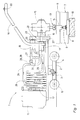
- a screwing machine 1 shown in FIG. 1 has a frame 2 which is movably connected via a joint 3 to a chassis 4 both about a vertical axis and about a horizontal axis running in the transverse direction of the track.
- This undercarriage 4 can be rolled off on a rail 6 of a track 7 via two double track roller wheels 5.
- the rails 6 rest on rib plates 8 and are connected to sleepers 10 by means of rail fastening screws 9.
- a motor 11 designed as an internal combustion engine
- a hydraulic pump 12 in the form of a gear pump, which are arranged on one longitudinal end of the frame 2 for reasons of balance.
- a screw head 13 which has a vertical screw spindle 14 and is connected via an angular gear 15 to a horizontally running drive shaft 16 of a first oil motor 17.
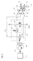
- the angular gear 15 is equipped with a turning stage which enables the direction of rotation of the screw spindle 14 to be reversed (see FIG. 2).
- a bracket 18 is used for manual lifting or lowering and lateral pivoting of the end of the frame 2 having the screw head 13 around the joint 3.
- a second oil motor 19 is provided for optional additional torque transmission to the screw head 13 and is connected to a housing 20 of a transmission 21.
- This single-stage gear 21 has a freewheel 22 which is arranged coaxially to the drive shaft 16 and which is in permanent engagement with a drive pinion 23 of the second oil motor 19 and allows the drive shaft 16 to rotate independently of the gear 21 through the first oil motor 17.
- the two oil motors 17, 19 can be acted upon by the hydraulic pump 12 via a working line 24 and are further connected to a return line 25, which is partially in the form of a cooling coil 26.
- the suction side of the second oil motor 19 is connected to the working line 24 (and thus to the hydraulic pump 12) via a supply line 27 in which a cut-in valve 28 is arranged.
- This is designed as a pilot-operated pressure relief valve 29, which is activated or opened when a predetermined pressure in the working line 24 is reached.
- the supply line 27 is connected to the return line 25 via a line 30 which contains a pressure control valve 31. This is also pre-controlled and switches to circulation when a predetermined pressure in the feed line 27 is reached.
- a magnetically controlled circulation valve 32 is provided between the working line 24 and the return line 25, with which (according to the position of the valve shown here) both oil motors 17, 19 can be taken out of operation while the hydraulic pump 12 is running.
- the screw spindle 14 is placed on the screw using the bracket 18. Then, by closing the circulation valve 32 via an operating switch 33, the first oil motor 17 is acted upon via the working line 24 (with the connecting valve 28 closed). Due to the free running of the transmission 21, the second oil motor 19 is not positively coupled to the drive shaft 16. The first oil motor 17 now drives the screw spindle 14 at high speed, with only very little resistance being provided by the screw in this first screw-in phase. However, once the screw is tightened, there is an increase in the pressure in the working line 24 as a result of the higher torque now required.
- the pilot-operated cut-in valve 28 or pressure-limiting valve 29 opens automatically, and the second oil motor 19 is acted upon in parallel to the first oil motor 17. Due to the presence of the gear 21 with the freewheel, there is automatically a force compensation between the two oil motors 17 and 19, which results in a second, slower rotational speed with a correspondingly higher torque transmitted to the drive shaft 16, with which the screw in the desired end position is tightened. Reaching the same is signaled by the pressure in the hydraulic system rising to a predetermined value, at which the pressure control valve 31 is activated and - by automatically switching over to circulation - the oil motors 17, 19 are put out of operation. This completes the screwing process without any action by the operator.
Landscapes
- Engineering & Computer Science (AREA)
- General Engineering & Computer Science (AREA)
- Mechanical Engineering (AREA)
- Architecture (AREA)
- Civil Engineering (AREA)
- Structural Engineering (AREA)
- Fluid-Pressure Circuits (AREA)
- Details Of Spanners, Wrenches, And Screw Drivers And Accessories (AREA)
- Dowels (AREA)
Applications Claiming Priority (2)
| Application Number | Priority Date | Filing Date | Title |
|---|---|---|---|
| DE19532826 | 1995-09-06 | ||
| DE19532826A DE19532826A1 (de) | 1995-09-06 | 1995-09-06 | Schraubmaschine |
Publications (1)
| Publication Number | Publication Date |
|---|---|
| EP0761881A1 true EP0761881A1 (fr) | 1997-03-12 |
Family
ID=7771364
Family Applications (1)
| Application Number | Title | Priority Date | Filing Date |
|---|---|---|---|
| EP96111876A Withdrawn EP0761881A1 (fr) | 1995-09-06 | 1996-07-24 | Machine visseuse |
Country Status (8)
| Country | Link |
|---|---|
| EP (1) | EP0761881A1 (fr) |
| BG (1) | BG100833A (fr) |
| CZ (1) | CZ252896A3 (fr) |
| DE (1) | DE19532826A1 (fr) |
| HR (1) | HRP960408A2 (fr) |
| HU (1) | HUP9602420A2 (fr) |
| PL (1) | PL315923A1 (fr) |
| SK (1) | SK113896A3 (fr) |
Cited By (4)
| Publication number | Priority date | Publication date | Assignee | Title |
|---|---|---|---|---|
| WO2006031168A1 (fr) * | 2004-09-17 | 2006-03-23 | Rosenqvist Rail Tech Ab | Dispositif facilement manoeuvrable |
| WO2006058552A1 (fr) * | 2004-12-03 | 2006-06-08 | Robel Bahnbaumaschinen Gmbh | Tirefonneuse |
| EP1983230A1 (fr) * | 2007-04-18 | 2008-10-22 | NAF Neunkirchener Achsenfabrik AG | Dispositif de transmission pour un véhicule automobile et véhicule automobile |
| WO2015118334A3 (fr) * | 2014-02-05 | 2015-11-19 | Forum Energy Technologies (Uk) Limited | Outil de couple, ensemble moteur et procédés d'utilisation |
Citations (4)
| Publication number | Priority date | Publication date | Assignee | Title |
|---|---|---|---|---|
| FR1533959A (fr) * | 1967-06-12 | 1968-07-26 | Ind De La Varenne | Machine pour le vissage et le dévissage des tirefonds de voies ferrées |
| DE2943938A1 (de) * | 1979-10-31 | 1981-05-14 | Georg Robel GmbH & Co, 8000 München | Ein- oder mehrspindelige schraubmaschine zum eidrehen und loesen von muttern und schrauben, insbesondere schienenbefestigungsmittel |
| EP0169753A2 (fr) * | 1984-07-27 | 1986-01-29 | Societe Turripinoise De Mecanique (S.A.R.L.) | Dispositif d'entraînement de l'arbre porte-clef d'une machine à tirefonner |
| DE9407064U1 (de) * | 1994-04-28 | 1994-10-20 | Georg Robel GmbH & Co, 81371 München | Schraubmaschine |
-
1995
- 1995-09-06 DE DE19532826A patent/DE19532826A1/de not_active Withdrawn
-
1996
- 1996-07-24 EP EP96111876A patent/EP0761881A1/fr not_active Withdrawn
- 1996-08-28 CZ CZ962528A patent/CZ252896A3/cs unknown
- 1996-09-02 PL PL96315923A patent/PL315923A1/xx unknown
- 1996-09-04 HU HU9602420A patent/HUP9602420A2/hu unknown
- 1996-09-04 SK SK1138-96A patent/SK113896A3/sk unknown
- 1996-09-06 BG BG100833A patent/BG100833A/xx unknown
- 1996-09-06 HR HR19532826.4A patent/HRP960408A2/hr not_active Application Discontinuation
Patent Citations (4)
| Publication number | Priority date | Publication date | Assignee | Title |
|---|---|---|---|---|
| FR1533959A (fr) * | 1967-06-12 | 1968-07-26 | Ind De La Varenne | Machine pour le vissage et le dévissage des tirefonds de voies ferrées |
| DE2943938A1 (de) * | 1979-10-31 | 1981-05-14 | Georg Robel GmbH & Co, 8000 München | Ein- oder mehrspindelige schraubmaschine zum eidrehen und loesen von muttern und schrauben, insbesondere schienenbefestigungsmittel |
| EP0169753A2 (fr) * | 1984-07-27 | 1986-01-29 | Societe Turripinoise De Mecanique (S.A.R.L.) | Dispositif d'entraînement de l'arbre porte-clef d'une machine à tirefonner |
| DE9407064U1 (de) * | 1994-04-28 | 1994-10-20 | Georg Robel GmbH & Co, 81371 München | Schraubmaschine |
Cited By (6)
| Publication number | Priority date | Publication date | Assignee | Title |
|---|---|---|---|---|
| WO2006031168A1 (fr) * | 2004-09-17 | 2006-03-23 | Rosenqvist Rail Tech Ab | Dispositif facilement manoeuvrable |
| WO2006058552A1 (fr) * | 2004-12-03 | 2006-06-08 | Robel Bahnbaumaschinen Gmbh | Tirefonneuse |
| EA010555B1 (ru) * | 2004-12-03 | 2008-10-30 | Робел Банбаумашинен Гмбх | Гайковерт |
| EP1983230A1 (fr) * | 2007-04-18 | 2008-10-22 | NAF Neunkirchener Achsenfabrik AG | Dispositif de transmission pour un véhicule automobile et véhicule automobile |
| WO2015118334A3 (fr) * | 2014-02-05 | 2015-11-19 | Forum Energy Technologies (Uk) Limited | Outil de couple, ensemble moteur et procédés d'utilisation |
| AU2015213892B2 (en) * | 2014-02-05 | 2019-04-18 | Forum Energy Technologies (Uk) Limited | Torque tool, motor assembly, and methods of use |
Also Published As
| Publication number | Publication date |
|---|---|
| CZ252896A3 (en) | 1997-03-12 |
| HUP9602420A2 (en) | 1997-05-28 |
| DE19532826A1 (de) | 1997-03-13 |
| BG100833A (en) | 1997-10-31 |
| HU9602420D0 (en) | 1996-11-28 |
| HRP960408A2 (en) | 1997-08-31 |
| PL315923A1 (en) | 1997-03-17 |
| SK113896A3 (en) | 1997-04-09 |
Similar Documents
| Publication | Publication Date | Title |
|---|---|---|
| DE3331211C2 (fr) | ||
| EP0936175A1 (fr) | Motorisation pour escalier roulant | |
| EP2260210B1 (fr) | Appareil de commande et son utilisation | |
| EP0761881A1 (fr) | Machine visseuse | |
| DE10255079A1 (de) | Einem Aggregate-Riementrieb einer Brennkraftmaschine zugeordnetes Reibradgetriebe für ein gesondertes Nebenaggregat | |
| DE112019008009T5 (de) | Ventilbetätiger | |
| DE2943938A1 (de) | Ein- oder mehrspindelige schraubmaschine zum eidrehen und loesen von muttern und schrauben, insbesondere schienenbefestigungsmittel | |
| DE202011102648U1 (de) | Getriebe für elektrische Fahrzeuge | |
| DD207517B1 (de) | Einrichtung zum positionieren an druckmaschinen | |
| EP0246631A1 (fr) | Installation de propulsion pour navires | |
| EP0761882B1 (fr) | Machine pour l'exécution de travaux de voie ferrée | |
| EP0873901A2 (fr) | Entraínement pour un appareil de travail mobile | |
| DD135876B1 (de) | Antriebsanordnung insbesondere fuer spritzgiessmaschinen | |
| DE2414409C2 (de) | Steuerung zum zwangsläufigen Einstellen des Gewichtsausgleiches des Stößels samt Oberwerkzeug einer Presse | |
| DE3814211C1 (en) | Drive mechanism for a twin-screw extruder | |
| DD200234A1 (de) | Verfahren zur steuerung von antriebsmotor und fahrantrieb bei selbstfahrenden arbeitsmaschinen | |
| DE420488C (de) | Tischantrieb fuer Werkzeug-, insonderheit fuer Schleifmaschinen | |
| DE738552C (de) | Kraftmaschinenregler | |
| DE102007043376A1 (de) | Antriebsvorrichtung mit Drehmomentkompensation | |
| DE503579C (de) | Werkzeugmaschine mit einem Maschinenteil, welcher gleichzeitig zwei Bewegungen ausfuehrt | |
| DE956311C (de) | Steuereinrichtung fuer Triebfahrzeuge, die mittels Brennkraftmaschine und kontinuierlich verstellbarem Reibraedergetriebe angetrieben werden | |
| DE708853C (de) | Stufenschaltvorrichtung, insbesondere fuer Transformatoren, mit Spannwerks-Malteserkreuzgetriebe | |
| EP0784174A2 (fr) | Armature avec un servomoteur électrique | |
| DE709501C (de) | Anstellvorrichtung fuer die Walzen von Walzwerken | |
| DE460773C (de) | Verfahren zum Anfahren von Diesellokomotiven und aehnlichen Fahrzeugen |
Legal Events
| Date | Code | Title | Description |
|---|---|---|---|
| PUAI | Public reference made under article 153(3) epc to a published international application that has entered the european phase |
Free format text: ORIGINAL CODE: 0009012 |
|
| 17P | Request for examination filed |
Effective date: 19960821 |
|
| AK | Designated contracting states |
Kind code of ref document: A1 Designated state(s): AT BE CH DE DK ES FR GB IT LI NL SE |
|
| 17Q | First examination report despatched |
Effective date: 19971021 |
|
| STAA | Information on the status of an ep patent application or granted ep patent |
Free format text: STATUS: THE APPLICATION IS DEEMED TO BE WITHDRAWN |
|
| 18D | Application deemed to be withdrawn |
Effective date: 19980303 |