EP0761882A1 - Machine pour l'exécution de travaux de voie ferrée - Google Patents
Machine pour l'exécution de travaux de voie ferrée Download PDFInfo
- Publication number
- EP0761882A1 EP0761882A1 EP96111983A EP96111983A EP0761882A1 EP 0761882 A1 EP0761882 A1 EP 0761882A1 EP 96111983 A EP96111983 A EP 96111983A EP 96111983 A EP96111983 A EP 96111983A EP 0761882 A1 EP0761882 A1 EP 0761882A1
- Authority
- EP
- European Patent Office
- Prior art keywords
- oil
- machine
- oil cooler
- drive shaft
- hydraulic line
- Prior art date
- Legal status (The legal status is an assumption and is not a legal conclusion. Google has not performed a legal analysis and makes no representation as to the accuracy of the status listed.)
- Granted
Links
- 238000002485 combustion reaction Methods 0.000 claims abstract description 5
- 238000006073 displacement reaction Methods 0.000 claims description 2
- 230000005540 biological transmission Effects 0.000 description 2
- 238000010276 construction Methods 0.000 description 1
- 238000001816 cooling Methods 0.000 description 1
- 238000011161 development Methods 0.000 description 1
- 230000018109 developmental process Effects 0.000 description 1
- 238000010586 diagram Methods 0.000 description 1
Images

Classifications
-
- E—FIXED CONSTRUCTIONS
- E01—CONSTRUCTION OF ROADS, RAILWAYS, OR BRIDGES
- E01B—PERMANENT WAY; PERMANENT-WAY TOOLS; MACHINES FOR MAKING RAILWAYS OF ALL KINDS
- E01B29/00—Laying, rebuilding, or taking-up tracks; Tools or machines therefor
- E01B29/24—Fixing or removing detachable fastening means or accessories thereof; Pre-assembling track components by detachable fastening means
- E01B29/28—Fixing or removing detachable fastening means or accessories thereof; Pre-assembling track components by detachable fastening means the fastening means being of screw-and-nut type; Apparatus therefor, adapted to additionally drilling holes
Definitions
- the invention relates to a machine for performing track superstructure work, with a machine frame provided by a handle for manual displacement along a track and supported on a wheel flange, a work unit which can be set into a working movement by an oil motor, an internal combustion engine, one with an oil pump and the oil motor connected hydraulic line and with a ventilated oil cooler.
- Such a hydraulic screwing machine known from DE 29 43 938 A1 has an adjustable hydraulic pump and an oil motor which is connected coaxially to a screwing head and drives it directly.
- the oil flow is infinitely adjustable with the aid of a flow rate regulator, whereby a pressure regulator switches the pump to circulation to avoid torque peaks when a desired pressure is reached.
- a pressure regulator switches the pump to circulation to avoid torque peaks when a desired pressure is reached.
- the object of the present invention is to create a machine of the generic type which enables improved handling by reducing the machine mass while maintaining the hydraulic system as the drive medium for the working unit.
- this object is achieved with a machine of the type described in the introduction in that the oil cooler is formed by a section of the hydraulic line in which the hydraulic line is guided spirally around a fan.
- the mass for the oil tank can be saved and the cooling itself can be simplified even with further mass reduction, since with this oil cooler design also for the hydraulic circuit less oil is required, mass can also be saved in this regard.
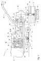
- a machine 1 shown in FIG. 1 for carrying out screwing work on the track superstructure has a machine frame 2 which is movably connected via a joint 3 to a chassis 4 both about a vertical axis and about a horizontal axis running in the transverse direction of the track.
- This undercarriage 4 can be rolled off on a rail 6 of a track 7 via two double track roller wheels 5.
- the rails 6 rest on rib plates 8 and are connected to sleepers 10 by means of rail fastening screws 9.
- An internal combustion engine 11 and an oil pump 12 in the form of a gear pump are fastened on the machine frame 2 and are arranged on one longitudinal end of the machine frame 2 for reasons of balance.
- a screw head 13 which has a vertical screw spindle 14 and is connected via an angular gear 15 to a horizontally running drive shaft 16 of a first oil motor 17.
- the angular gear 15 is equipped with a turning stage which enables the direction of rotation of the screw spindle 14 to be reversed.
- a handle 18 connected to the machine frame 2 is used to manually raise or lower the end of the machine frame 2 having the screw head 13 around the joint 3 and also to move the machine 1 to the next screwing point.
- a second oil motor 19 is provided for optional additional torque transmission to the screw head 13 and is connected to a housing 20 of a transmission 21.
- This single-stage gear 21 has a free wheel 22 arranged coaxially around the drive shaft 16, which is in permanent engagement with a drive pinion 23 of the second oil motor 19 and allows the drive shaft 16 to rotate independently of the gear 21 through the first oil motor 17.
- Both oil motors 17, 19 are connected to the oil pump 12 via hydraulic lines 34. These hydraulic lines are composed of a working line 24 and a return line 25.
- a section 35 of the return line 25 of the hydraulic line 34 adjoining the oil pump 12 is guided spirally around a fan 37 to form an oil cooler 36.
- this fan 37 is fastened to a drive shaft 38 of the oil pump 12.
- the section 35, which is spirally wound and forms the oil cooler 36, is cylindrical, the drive shaft 38 running coaxially with a longitudinal axis 39 of the cylindrical oil cooler 36.
- the suction side of the second oil motor 19 is connected to the working line 24 and thereby to the oil pump 12 via a supply line 27 in which a connection valve 28 is arranged.
- This is designed as a pilot-operated pressure relief valve 29, which is activated or opened when a predetermined pressure in the working line 24 is reached.
- the supply line 27 is connected to the return line 25 via a line 30 which contains a pressure control valve 31. This is also pre-controlled and switches to circulation when a predetermined pressure in the feed line 27 is reached.
- a circulation valve 32 is provided between the working line 24 and the return line 25, with which both oil motors 17, 19 can be taken out of operation while the oil pump 12 is running.
- the rotation of the screw spindle 14, which is generally also referred to as the working unit 40, is initiated by actuating an operating switch 33 and actuating the first oil motor 17.
- an operating switch 33 As soon as the screw has been tightened, the pressure in the working line 24 rises.
- the pilot-operated switching valve 28 or pressure limiting valve opens 29 automatically and the second oil motor 19 is connected in parallel to the first oil motor 17.
- a small expansion tank 41 is provided in the hydraulic line 34.
- a grinding tool, a drill or another tool which can be used in conjunction with a manually displaceable track construction machine can also be used as the working unit 40.
Landscapes
- Engineering & Computer Science (AREA)
- Architecture (AREA)
- Civil Engineering (AREA)
- Structural Engineering (AREA)
- Lubrication Of Internal Combustion Engines (AREA)
- Cooling, Air Intake And Gas Exhaust, And Fuel Tank Arrangements In Propulsion Units (AREA)
- Road Paving Machines (AREA)
- Transplanting Machines (AREA)
- Soil Working Implements (AREA)
- Lubricants (AREA)
- Electrical Discharge Machining, Electrochemical Machining, And Combined Machining (AREA)
Priority Applications (1)
| Application Number | Priority Date | Filing Date | Title |
|---|---|---|---|
| DE29623717U DE29623717U1 (de) | 1995-09-06 | 1996-07-25 | Maschine zur Durchführung von Gleisoberbauarbeiten |
Applications Claiming Priority (2)
| Application Number | Priority Date | Filing Date | Title |
|---|---|---|---|
| DE19532827A DE19532827A1 (de) | 1995-09-06 | 1995-09-06 | Maschine zur Durchführung von Gleisoberbauarbeiten |
| DE19532827 | 1995-09-06 |
Publications (2)
| Publication Number | Publication Date |
|---|---|
| EP0761882A1 true EP0761882A1 (fr) | 1997-03-12 |
| EP0761882B1 EP0761882B1 (fr) | 2001-01-24 |
Family
ID=7771365
Family Applications (1)
| Application Number | Title | Priority Date | Filing Date |
|---|---|---|---|
| EP96111983A Expired - Lifetime EP0761882B1 (fr) | 1995-09-06 | 1996-07-25 | Machine pour l'exécution de travaux de voie ferrée |
Country Status (5)
| Country | Link |
|---|---|
| EP (1) | EP0761882B1 (fr) |
| AT (1) | ATE198918T1 (fr) |
| DE (2) | DE19532827A1 (fr) |
| DK (1) | DK0761882T3 (fr) |
| ES (1) | ES2155553T3 (fr) |
Cited By (1)
| Publication number | Priority date | Publication date | Assignee | Title |
|---|---|---|---|---|
| CN111254763A (zh) * | 2020-01-19 | 2020-06-09 | 绍兴华阳铁路器材有限公司 | 液压起拔道器 |
Families Citing this family (2)
| Publication number | Priority date | Publication date | Assignee | Title |
|---|---|---|---|---|
| US8222005B2 (en) * | 2003-09-17 | 2012-07-17 | Agency For Science, Technology And Research | Method for gene identification signature (GIS) analysis |
| DE102012017270B4 (de) * | 2012-08-31 | 2017-06-22 | Deutsche Bahnbaugruppe GmbH | Schienenwagen zur Aufnahme eines motorisch betriebenen Schraubwerkzeuges |
Citations (4)
| Publication number | Priority date | Publication date | Assignee | Title |
|---|---|---|---|---|
| CH429392A (de) * | 1965-10-08 | 1967-01-31 | Elektro Thermit Gmbh | Verfahren und Vorrichtung zur profilgerechten Abarbeitung von bei der Schienenverbindungsschweissung entstandenen Schweisswülsten bzw. Schweissgutüberständen |
| DE1248692B (fr) * | 1967-08-31 | |||
| DE2943938A1 (de) * | 1979-10-31 | 1981-05-14 | Georg Robel GmbH & Co, 8000 München | Ein- oder mehrspindelige schraubmaschine zum eidrehen und loesen von muttern und schrauben, insbesondere schienenbefestigungsmittel |
| DE9407064U1 (de) * | 1994-04-28 | 1994-10-20 | Georg Robel GmbH & Co, 81371 München | Schraubmaschine |
Family Cites Families (3)
| Publication number | Priority date | Publication date | Assignee | Title |
|---|---|---|---|---|
| DE2626770A1 (de) * | 1976-06-15 | 1977-12-22 | Inst Cercetare Si Proiectare T | Kuehler fuer hydraulische anlagen |
| DE3410071C2 (de) * | 1984-03-20 | 1994-06-01 | Bosch Gmbh Robert | Hydraulikanlage |
| FR2650030A1 (fr) * | 1989-07-20 | 1991-01-25 | Micto Voiries Ind | Dispositif pour le refroidissement de l'huile des moteurs hydrauliques d'un vehicule leger destine a l'aspiration et au nettoyage |
-
1995
- 1995-09-06 DE DE19532827A patent/DE19532827A1/de not_active Withdrawn
-
1996
- 1996-07-25 AT AT96111983T patent/ATE198918T1/de active
- 1996-07-25 DE DE59606367T patent/DE59606367D1/de not_active Expired - Lifetime
- 1996-07-25 DK DK96111983T patent/DK0761882T3/da active
- 1996-07-25 ES ES96111983T patent/ES2155553T3/es not_active Expired - Lifetime
- 1996-07-25 EP EP96111983A patent/EP0761882B1/fr not_active Expired - Lifetime
Patent Citations (4)
| Publication number | Priority date | Publication date | Assignee | Title |
|---|---|---|---|---|
| DE1248692B (fr) * | 1967-08-31 | |||
| CH429392A (de) * | 1965-10-08 | 1967-01-31 | Elektro Thermit Gmbh | Verfahren und Vorrichtung zur profilgerechten Abarbeitung von bei der Schienenverbindungsschweissung entstandenen Schweisswülsten bzw. Schweissgutüberständen |
| DE2943938A1 (de) * | 1979-10-31 | 1981-05-14 | Georg Robel GmbH & Co, 8000 München | Ein- oder mehrspindelige schraubmaschine zum eidrehen und loesen von muttern und schrauben, insbesondere schienenbefestigungsmittel |
| DE9407064U1 (de) * | 1994-04-28 | 1994-10-20 | Georg Robel GmbH & Co, 81371 München | Schraubmaschine |
Cited By (2)
| Publication number | Priority date | Publication date | Assignee | Title |
|---|---|---|---|---|
| CN111254763A (zh) * | 2020-01-19 | 2020-06-09 | 绍兴华阳铁路器材有限公司 | 液压起拔道器 |
| CN111254763B (zh) * | 2020-01-19 | 2021-10-15 | 绍兴华阳铁路器材有限公司 | 液压起拔道器 |
Also Published As
| Publication number | Publication date |
|---|---|
| ES2155553T3 (es) | 2001-05-16 |
| DE19532827A1 (de) | 1997-03-13 |
| DE59606367D1 (de) | 2001-03-01 |
| ATE198918T1 (de) | 2001-02-15 |
| EP0761882B1 (fr) | 2001-01-24 |
| DK0761882T3 (da) | 2001-02-26 |
Similar Documents
| Publication | Publication Date | Title |
|---|---|---|
| DE8915954U1 (de) | Stufenlos regelbarer hydrostatischer Fahrantrieb | |
| EP0761882B1 (fr) | Machine pour l'exécution de travaux de voie ferrée | |
| DE112019008009T5 (de) | Ventilbetätiger | |
| DE2943938A1 (de) | Ein- oder mehrspindelige schraubmaschine zum eidrehen und loesen von muttern und schrauben, insbesondere schienenbefestigungsmittel | |
| EP0069388A1 (fr) | Support de cylindres d'impression ou similaires, avec dispositif de réglage du repèrage latéral | |
| DE19717708A1 (de) | Antrieb für ein fahrbares Arbeitsgerät | |
| EP0701872A1 (fr) | Installation d'entraînement à trois dimensions de barres porteuses | |
| DE3107459A1 (de) | Vorrichtung zur hoehen- und neigungsverstellung von lenkraedern | |
| DE3144348C2 (fr) | ||
| DE29623717U1 (de) | Maschine zur Durchführung von Gleisoberbauarbeiten | |
| DE4414886C2 (de) | Schraubmaschine | |
| DD207517B1 (de) | Einrichtung zum positionieren an druckmaschinen | |
| DD135876B1 (de) | Antriebsanordnung insbesondere fuer spritzgiessmaschinen | |
| DE3109851C2 (fr) | ||
| DE19532826A1 (de) | Schraubmaschine | |
| DE3137553C2 (de) | Vorschubeinrichtung für eine aus einzelnen Baueinheiten bestehende Gewinnungsmaschine des Untertagebergbaues | |
| EP0708012B1 (fr) | Direction assistée pour véhicules à moteur | |
| WO2002046020A1 (fr) | Mecanisme de direction a orientation par cables a actionneur a retroaction hydraulique | |
| AT369808B (de) | Ein- oder mehrspindelige schraubmaschine zum eindrehen und loesen von muttern und schrauben insbesondere schienenbefestigungsmitteln | |
| DE3305588C2 (de) | Spindelpresse mit ständig umlaufender, gleichsinnig angetriebener Schwungscheibe | |
| DE2365635A1 (de) | Zugmaschine zum diesel-hydraulischen antrieb von schienenstandbahnen des unterlageberghaus | |
| DE9407064U1 (de) | Schraubmaschine | |
| DE1527062C (de) | Kupplung zur Verbindung zweier auf einem gemeinsamen Bett gelagerter Werkzeug maschinentische | |
| DE10048697A1 (de) | Steer-by-Wire-Lenkanlage mit Zahnstangen-Hydrolenksteller | |
| DD249219A1 (de) | Mehrfachschrauber |
Legal Events
| Date | Code | Title | Description |
|---|---|---|---|
| PUAI | Public reference made under article 153(3) epc to a published international application that has entered the european phase |
Free format text: ORIGINAL CODE: 0009012 |
|
| 17P | Request for examination filed |
Effective date: 19960821 |
|
| AK | Designated contracting states |
Kind code of ref document: A1 Designated state(s): AT BE CH DE DK ES FR GB IT LI NL SE |
|
| 17Q | First examination report despatched |
Effective date: 19980605 |
|
| RAP1 | Party data changed (applicant data changed or rights of an application transferred) |
Owner name: ROBEL GMBH & CO. KG |
|
| GRAG | Despatch of communication of intention to grant |
Free format text: ORIGINAL CODE: EPIDOS AGRA |
|
| GRAG | Despatch of communication of intention to grant |
Free format text: ORIGINAL CODE: EPIDOS AGRA |
|
| GRAH | Despatch of communication of intention to grant a patent |
Free format text: ORIGINAL CODE: EPIDOS IGRA |
|
| GRAH | Despatch of communication of intention to grant a patent |
Free format text: ORIGINAL CODE: EPIDOS IGRA |
|
| GRAA | (expected) grant |
Free format text: ORIGINAL CODE: 0009210 |
|
| AK | Designated contracting states |
Kind code of ref document: B1 Designated state(s): AT BE CH DE DK ES FR GB IT LI NL SE |
|
| REF | Corresponds to: |
Ref document number: 198918 Country of ref document: AT Date of ref document: 20010215 Kind code of ref document: T |
|
| REG | Reference to a national code |
Ref country code: CH Ref legal event code: NV Representative=s name: DIPL.-ING. ETH H. R. WERFFELI PATENTANWALT Ref country code: CH Ref legal event code: EP |
|
| ITF | It: translation for a ep patent filed | ||
| RAP2 | Party data changed (patent owner data changed or rights of a patent transferred) |
Owner name: ROBEL BAHNBAUMASCHINEN GMBH |
|
| REG | Reference to a national code |
Ref country code: DK Ref legal event code: T3 |
|
| GBT | Gb: translation of ep patent filed (gb section 77(6)(a)/1977) |
Effective date: 20010206 |
|
| REG | Reference to a national code |
Ref country code: CH Ref legal event code: PUE Owner name: ROBEL GMBH & CO. KG TRANSFER- ROBEL BAHNBAUMASCHIN |
|
| REF | Corresponds to: |
Ref document number: 59606367 Country of ref document: DE Date of ref document: 20010301 |
|
| ET | Fr: translation filed | ||
| NLT2 | Nl: modifications (of names), taken from the european patent patent bulletin |
Owner name: ROBEL BAHNBAUMASCHINEN GMBH |
|
| NLXE | Nl: other communications concerning ep-patents (part 3 heading xe) |
Free format text: PAT. BUL. 03/2001 PAGE 298: CORR.: ROBEL BAHNBAUMASCHINEN GMBH |
|
| REG | Reference to a national code |
Ref country code: ES Ref legal event code: FG2A Ref document number: 2155553 Country of ref document: ES Kind code of ref document: T3 |
|
| PLBE | No opposition filed within time limit |
Free format text: ORIGINAL CODE: 0009261 |
|
| STAA | Information on the status of an ep patent application or granted ep patent |
Free format text: STATUS: NO OPPOSITION FILED WITHIN TIME LIMIT |
|
| REG | Reference to a national code |
Ref country code: GB Ref legal event code: IF02 |
|
| 26N | No opposition filed | ||
| PGFP | Annual fee paid to national office [announced via postgrant information from national office to epo] |
Ref country code: DE Payment date: 20120726 Year of fee payment: 17 |
|
| PGFP | Annual fee paid to national office [announced via postgrant information from national office to epo] |
Ref country code: CH Payment date: 20130723 Year of fee payment: 18 Ref country code: ES Payment date: 20130722 Year of fee payment: 18 Ref country code: BE Payment date: 20130722 Year of fee payment: 18 Ref country code: AT Payment date: 20130722 Year of fee payment: 18 Ref country code: SE Payment date: 20130723 Year of fee payment: 18 Ref country code: NL Payment date: 20130722 Year of fee payment: 18 Ref country code: DK Payment date: 20130724 Year of fee payment: 18 |
|
| PGFP | Annual fee paid to national office [announced via postgrant information from national office to epo] |
Ref country code: GB Payment date: 20130723 Year of fee payment: 18 Ref country code: FR Payment date: 20130719 Year of fee payment: 18 |
|
| PGFP | Annual fee paid to national office [announced via postgrant information from national office to epo] |
Ref country code: IT Payment date: 20130730 Year of fee payment: 18 |
|
| REG | Reference to a national code |
Ref country code: DE Ref legal event code: R119 Ref document number: 59606367 Country of ref document: DE Effective date: 20140201 |
|
| PG25 | Lapsed in a contracting state [announced via postgrant information from national office to epo] |
Ref country code: DE Free format text: LAPSE BECAUSE OF NON-PAYMENT OF DUE FEES Effective date: 20140201 |
|
| REG | Reference to a national code |
Ref country code: DK Ref legal event code: EBP Effective date: 20140731 |
|
| REG | Reference to a national code |
Ref country code: NL Ref legal event code: V1 Effective date: 20150201 |
|
| REG | Reference to a national code |
Ref country code: CH Ref legal event code: PL |
|
| REG | Reference to a national code |
Ref country code: SE Ref legal event code: EUG |
|
| REG | Reference to a national code |
Ref country code: AT Ref legal event code: MM01 Ref document number: 198918 Country of ref document: AT Kind code of ref document: T Effective date: 20140725 |
|
| GBPC | Gb: european patent ceased through non-payment of renewal fee |
Effective date: 20140725 |
|
| PG25 | Lapsed in a contracting state [announced via postgrant information from national office to epo] |
Ref country code: NL Free format text: LAPSE BECAUSE OF NON-PAYMENT OF DUE FEES Effective date: 20150201 |
|
| REG | Reference to a national code |
Ref country code: FR Ref legal event code: ST Effective date: 20150331 |
|
| PG25 | Lapsed in a contracting state [announced via postgrant information from national office to epo] |
Ref country code: CH Free format text: LAPSE BECAUSE OF NON-PAYMENT OF DUE FEES Effective date: 20140731 Ref country code: IT Free format text: LAPSE BECAUSE OF NON-PAYMENT OF DUE FEES Effective date: 20140725 Ref country code: LI Free format text: LAPSE BECAUSE OF NON-PAYMENT OF DUE FEES Effective date: 20140731 |
|
| PG25 | Lapsed in a contracting state [announced via postgrant information from national office to epo] |
Ref country code: SE Free format text: LAPSE BECAUSE OF NON-PAYMENT OF DUE FEES Effective date: 20140726 Ref country code: FR Free format text: LAPSE BECAUSE OF NON-PAYMENT OF DUE FEES Effective date: 20140731 Ref country code: GB Free format text: LAPSE BECAUSE OF NON-PAYMENT OF DUE FEES Effective date: 20140725 Ref country code: AT Free format text: LAPSE BECAUSE OF NON-PAYMENT OF DUE FEES Effective date: 20140725 |
|
| PG25 | Lapsed in a contracting state [announced via postgrant information from national office to epo] |
Ref country code: DK Free format text: LAPSE BECAUSE OF NON-PAYMENT OF DUE FEES Effective date: 20140731 |
|
| REG | Reference to a national code |
Ref country code: ES Ref legal event code: FD2A Effective date: 20150826 |
|
| PG25 | Lapsed in a contracting state [announced via postgrant information from national office to epo] |
Ref country code: ES Free format text: LAPSE BECAUSE OF NON-PAYMENT OF DUE FEES Effective date: 20140726 |
|
| PG25 | Lapsed in a contracting state [announced via postgrant information from national office to epo] |
Ref country code: BE Free format text: LAPSE BECAUSE OF NON-PAYMENT OF DUE FEES Effective date: 20140731 |