EP0761883B1 - Elément de pavage autobloquant - Google Patents
Elément de pavage autobloquant Download PDFInfo
- Publication number
- EP0761883B1 EP0761883B1 EP96113217A EP96113217A EP0761883B1 EP 0761883 B1 EP0761883 B1 EP 0761883B1 EP 96113217 A EP96113217 A EP 96113217A EP 96113217 A EP96113217 A EP 96113217A EP 0761883 B1 EP0761883 B1 EP 0761883B1
- Authority
- EP
- European Patent Office
- Prior art keywords
- sides
- interlocking paving
- elements
- interlocking
- paving stone
- Prior art date
- Legal status (The legal status is an assumption and is not a legal conclusion. Google has not performed a legal analysis and makes no representation as to the accuracy of the status listed.)
- Expired - Lifetime
Links
- 239000004575 stone Substances 0.000 claims abstract description 74
- 239000002131 composite material Substances 0.000 description 46
- XLYOFNOQVPJJNP-UHFFFAOYSA-N water Substances O XLYOFNOQVPJJNP-UHFFFAOYSA-N 0.000 description 13
- 238000004519 manufacturing process Methods 0.000 description 5
- 150000001875 compounds Chemical class 0.000 description 4
- 239000011505 plaster Substances 0.000 description 3
- 230000015572 biosynthetic process Effects 0.000 description 2
- 230000001427 coherent effect Effects 0.000 description 2
- 238000011161 development Methods 0.000 description 2
- 230000018109 developmental process Effects 0.000 description 2
- 238000001035 drying Methods 0.000 description 2
- 230000000694 effects Effects 0.000 description 2
- 230000009286 beneficial effect Effects 0.000 description 1
- 238000011010 flushing procedure Methods 0.000 description 1
- 230000008595 infiltration Effects 0.000 description 1
- 238000001764 infiltration Methods 0.000 description 1
- 239000000463 material Substances 0.000 description 1
- 239000013589 supplement Substances 0.000 description 1
Images

Classifications
-
- E—FIXED CONSTRUCTIONS
- E01—CONSTRUCTION OF ROADS, RAILWAYS, OR BRIDGES
- E01C—CONSTRUCTION OF, OR SURFACES FOR, ROADS, SPORTS GROUNDS, OR THE LIKE; MACHINES OR AUXILIARY TOOLS FOR CONSTRUCTION OR REPAIR
- E01C11/00—Details of pavings
- E01C11/22—Gutters; Kerbs ; Surface drainage of streets, roads or like traffic areas
- E01C11/224—Surface drainage of streets
- E01C11/225—Paving specially adapted for through-the-surfacing drainage, e.g. perforated, porous; Preformed paving elements comprising, or adapted to form, passageways for carrying off drainage
-
- E—FIXED CONSTRUCTIONS
- E01—CONSTRUCTION OF ROADS, RAILWAYS, OR BRIDGES
- E01C—CONSTRUCTION OF, OR SURFACES FOR, ROADS, SPORTS GROUNDS, OR THE LIKE; MACHINES OR AUXILIARY TOOLS FOR CONSTRUCTION OR REPAIR
- E01C5/00—Pavings made of prefabricated single units
-
- E—FIXED CONSTRUCTIONS
- E01—CONSTRUCTION OF ROADS, RAILWAYS, OR BRIDGES
- E01C—CONSTRUCTION OF, OR SURFACES FOR, ROADS, SPORTS GROUNDS, OR THE LIKE; MACHINES OR AUXILIARY TOOLS FOR CONSTRUCTION OR REPAIR
- E01C2201/00—Paving elements
- E01C2201/02—Paving elements having fixed spacing features
-
- E—FIXED CONSTRUCTIONS
- E01—CONSTRUCTION OF ROADS, RAILWAYS, OR BRIDGES
- E01C—CONSTRUCTION OF, OR SURFACES FOR, ROADS, SPORTS GROUNDS, OR THE LIKE; MACHINES OR AUXILIARY TOOLS FOR CONSTRUCTION OR REPAIR
- E01C2201/00—Paving elements
- E01C2201/16—Elements joined together
Definitions
- the invention relates to a composite paving stone consisting of two out of six essentially consists of a hexagon-forming elements and a central part, the central part has four sides of a small hexagon and between the outer sides of the two elements a recess is provided, in which the two at an angle mutually facing sides of the central part of another composite paving stone, which has two more elements, can intervene and the hexagon by each one of two elements of other adjacent composite paving stones can be supplemented in this way is that the composite paving stones are joined together on all sides is possible, for which reason bevels between those facing the middle section continue Pages and the outside are provided.
- Such a composite paving stone is deposited from the design patent MR 974 at the district court in Ludwigshafen.
- Such composite paving stones can a closed surface are put together, with an intensive interlocking is achieved, which is suitable for pushing forces e.g. counteract when driving on the surface.
- this configuration enables an elegant design, by optically highlighting the elements that essentially form a hexagon and a flower pattern is created.
- a paving with such composite paving stones however, like all conventional paving, has the disadvantage that the surface is sealed, which is ecologically undesirable these days is.
- Another disadvantage is that cast materials harden during curing tend to bulge. These bulges led to the large contiguous areas of the individual Compound paving stones so that they no longer lie exactly against each other. That has to Consequence that the desired stability of the mutual interlocking of the paving stones is achieved.
- the invention is therefore based on the object, the composite paving stone of the beginning mentioned type in such a way that in a simple manner with simultaneous improvement the intensive interlocking perforations in the pavement for infiltration are achievable by water.
- the object is achieved in that pointing to the middle part On the sides and on the outside the joined composite paving stones bulges interrupted along the entire length of the sides is so that when the composite paving stones are lined up a bulge a composite paving stone with a bulge of another composite paving stone meets in such a way that an opening arises from the bulges.
- the composite paving stone according to the invention has the advantage that none in it Holes must be made and the manufacturing process thereby essential is simplified.
- the production of bulges in the areas mentioned is a much less manufacturing effort than the production of stones that have holes.
- the intensive interlocking of the composite paving stones is the beginning mentioned type, which already the interlocking of many known paving stones far exceeds, still significantly improved, since bulges on the large adjacent surfaces can no longer occur.
- the large areas are divided into two partial areas, which match the corresponding ones Part of the adjacent composite paving stone. It is coming this results in a smooth joining of the stones, which results in a cleaner laying with a significantly increased mutual interlocking is possible.
- the subclaims relate to further developments of the composite paving stone through which substantial further advantages can be achieved.
- the elevations create a relief-like structure of the surface, with the effect that the water leaves the raised area immediately and therefore dries it up within a very short time. There are dry spots shortly after rain and the pavement is easier to walk on. This quick drying is particularly advantageous in winter, since hardly any ice formation can occur at the elevations. In this way, the plaster ensures that scattering or mechanical removal of ice is hardly necessary.
- the composite paving stones are therefore particularly well suited for sidewalks and garage exits, especially if they have an incline.
- the central part also for increased water drainage is provided with an opening instead of an elevation.
- Another measure to improve water drainage is that the non-raised areas are designed in such a way that when composite paving stones are joined together result in a coherent canal system that drains through the openings becomes. In this way, the water flows from the elevations to the non-elevated ones Areas that are drained using the perforations. If you move one Compound plaster system still on a water-absorbing surface, for example Gravel, the water drainage is optimized in such a way that puddles no longer arise can. The ecologically desired effect of draining the water also at the heaviest downpours is guaranteed. An additional drainage is not more needed. This also leads to the already mentioned formation of ice in winter is almost always prevented.
- Another advantageous embodiment provides that the openings as elongated holes are trained.
- Such elongated holes are particularly easy to achieve in that the bulges of two composite paving stones that can be joined together.
- the opening inserted in the composite paving stone can also be considered Form the appropriate elongated hole.
- This has the advantage that the drainage holes do not clog as quickly as known small rounds Holes is the case.
- such elongated holes can be cleaned better because one them with an appropriately designed object, for example a knife, can easily get rid of dirt.
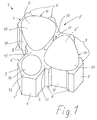
- FIG. 1 shows a composite paving stone 1 of the type according to the invention. It consists of two elements 2 and 2 ', which together with four further such elements 2 ", 2"', 2 “" and 2 “”'essentially form a hexagon 6 ( Fig. 2), and a middle part 3. This is attached to the two elements 2 and 2 'in such a way that four sides 4, 4', 4 "and 4"'of a small hexagon 12 are exposed.
- the two elements 2 and 2 ' form outer sides 9 and sides 8 facing the central part 3.
- the outer sides 9 of the two elements 2 and 2' include a recess 5 which is located at the point where a corner of the hexagon 6 would lie .
- This recess 5 is designed such that two sides 4 'and 4 "of the central part 3 of a further composite paving stone 1' which are at an angle to one another can be inserted into this recess 5.
- two further composite paving stones 1" and 1 " 2. Add as shown in Fig. 2.
- Each of two elements 2 "and 2"'of these adjoining composite paving stones 1 "and 1"' form such a supplement that the hexagon 6 is formed
- Joining two composite paving stones results in a shape that corresponds to the recess 5. It can also be a he insert such a middle part 3 of another composite paving stone, but this happens with the sides 4 and 4 'or 4 "and 4"'.
- the composite paving stones 1, 1 ', ... are thus constructed such that they are four of equal length, large pages, pages 8 and outer pages 9 and eight small pages of the same length, the sides 4, 4 ', 4 ", 4"' and the sides of the bevels 7 and the two sides of the recesses 5.
- the small sides are half as long as the large ones Pages.
- the composite paving stone corresponds to the known composite paving stone mentioned at the outset, which is further developed according to the invention in that bulges 10 are provided on the sides 8 and on the outer sides 9, which interrupt the sides 8 and the outer sides 9 such that these now consist of two smaller areas exist, which attach to the bulges 10 on both sides.
- Fig. 2 shows how when lining up the composite paving stones 1, 1 ', ...
- a bulge 10 of a composite paving stone 1' with a bulge 10 'of another composite paving stone 1 "meets such that an opening is formed from 10 and 10', which the In order to achieve a symmetrical impression and to improve water drainage, an opening 11 is provided between two elements 2 and 2 ', the shape of which corresponds to the opening formed by 10 and 10'.
- Fig. 2 shows that in this way Between two elements 2 and 2 ', 2' and 2 "etc., an opening 11 or 10 and 10 'comes to rest. In this way, the pavement is equipped with drainage holes that ensure safe water drainage. Furthermore, there is a better lining up of the composite paving stones 1, 1 ', ... since the surfaces of the sides 8 and the outer sides 9 can be better joined together by the subdivision.
- the elements 2, 2 ', ... are expediently designed as elevations 13, whereby the mentioned better water drainage and faster drying is achieved is.
- the middle part 3 can also be designed as an elevation 14.
- the elevation 14 another, for example round opening To be provided so that the water can drain off even better.
Landscapes
- Engineering & Computer Science (AREA)
- Architecture (AREA)
- Civil Engineering (AREA)
- Structural Engineering (AREA)
- Road Paving Structures (AREA)
- Curing Cements, Concrete, And Artificial Stone (AREA)
- Plural Heterocyclic Compounds (AREA)
Claims (7)
- Pavé autobloquant (1) qui se compose de deux (2, 2') éléments (2, 2', 2", 2"', 2"", 2""') formant sensiblement un hexagone (6) et d'une partie médiane (3), la partie médiane (3) présentant quatre côtés (4, 4', 4", 4"') d'un petit hexagone (12) et un évidement (5) étant prévu entre les faces externes (9) des deux éléments (2, 2') dans lequel peuvent s'engager les deux faces (4', 4"),, de la partie médiane (3) d'un autre pavé autobloquant (1') qui présente deux autres éléments (2"", 2""'), ces deux faces formant un angle entre elles ,et l'hexagone (6) pouvant être complété par l'un des deux éléments (2", 2"') d'autres pavés autobloquants adjacents (1", 1"'), de manière à permettre un assemblage des pavés autobloquants (1, 1', 1", 1"', 1"",...) en étant voisins de tous les côtés, auquel cas d'autres chanfreins (7) sont prévus entre les faces (8) tournées vers la partie médiane (3) et les faces externes (9),
caractérisé en ce que
sur les faces (8), tournées vers la partie médiane (3) et sur les faces externes (9), la contiguïté des pavés autobloquants assemblés (1, 1', 1", 1"',...) est interrompue sur l'ensemble des longueurs des faces (8, 9) par des cavités (10, 10') de sorte qu'à l'alignement des pavés autobloquants (1, 1', ...), une cavité (10) d'un pavé autobloquant (1') correspond à une cavité (10') d'un autre pavé autobloquant (1") de manière à obtenir un passage partir des cavités (10, 10'). - Pavé autobloquant selon la revendication 1,
caractérisé en ce qu'
entre les éléments (2, 2'), il est prévu un passage (11) qui présente une symétrie avec les cavités assemblées (10 et 10') quand les pavés autobloquants (1, 1', 1", 1"', 1"", ...) sont réunis. - Pavé autobloquant selon la revendication 1 or 2,
caractérisé en ce que
les éléments (2, 2', 2", ...) présentent des protubérances (13). - Pavé autobloquant selon la revendication 1, 2 ou 3
caractérisé en ce que
la partie médiane (3) présente une protubérance (14). - Pavé autobloquant selon la revendication 1, 2 ou 3
caractérisé en ce que
la partie médiane (3) présente un passage. - Pavé autobloquant selon l'une ou plusieurs des revendications 3, 4 ou 5,
caractérisé en ce que
les surfaces non surélevées (15) sont conçues de manière à former un système de canaux quand les pavés autobloquants (1, 1', 1", 1"', 1"", ...) sont assemblés, ce qui permet l'évacuation de l'eau par les passages (10, et 10', 11). - Pavé autobloquant selon l'une ou plusieurs des revendications à 6,
caractérisé en ce que
les passages (10 et 10', 11) sont conçus comme des trous oblongs.
Applications Claiming Priority (2)
| Application Number | Priority Date | Filing Date | Title |
|---|---|---|---|
| DE29514447U | 1995-09-08 | ||
| DE29514447U DE29514447U1 (de) | 1995-09-08 | 1995-09-08 | Verbundpflasterstein |
Publications (2)
| Publication Number | Publication Date |
|---|---|
| EP0761883A1 EP0761883A1 (fr) | 1997-03-12 |
| EP0761883B1 true EP0761883B1 (fr) | 1998-04-08 |
Family
ID=8012782
Family Applications (1)
| Application Number | Title | Priority Date | Filing Date |
|---|---|---|---|
| EP96113217A Expired - Lifetime EP0761883B1 (fr) | 1995-09-08 | 1996-08-17 | Elément de pavage autobloquant |
Country Status (3)
| Country | Link |
|---|---|
| EP (1) | EP0761883B1 (fr) |
| AT (1) | ATE164900T1 (fr) |
| DE (2) | DE29514447U1 (fr) |
Family Cites Families (4)
| Publication number | Priority date | Publication date | Assignee | Title |
|---|---|---|---|---|
| FR2277188A1 (fr) * | 1974-07-02 | 1976-01-30 | Const Indles Rationnelle | Pave |
| DE2905796A1 (de) * | 1979-02-15 | 1980-08-28 | Barth Gmbh Dr | Bodenbelagelement mit durch scheinfugen voneinander abgesetzten, erhoehten bereichen an der nutzseite, bodenbelagelementgruppe aus derartigen bodenbelagelementen und verfahren zur herstellung derartiger bodenbelagelemente |
| GB9211701D0 (en) * | 1992-06-03 | 1992-07-15 | Glickman Michael N | Paving block with improved water run-though |
| DE29506155U1 (de) * | 1995-04-08 | 1995-06-22 | Hiesl, Gerhard, Ing.(grad.), 88471 Laupheim | Drainagestein |
-
1995
- 1995-09-08 DE DE29514447U patent/DE29514447U1/de not_active Expired - Lifetime
-
1996
- 1996-08-17 AT AT96113217T patent/ATE164900T1/de not_active IP Right Cessation
- 1996-08-17 EP EP96113217A patent/EP0761883B1/fr not_active Expired - Lifetime
- 1996-08-17 DE DE59600145T patent/DE59600145D1/de not_active Expired - Fee Related
Also Published As
| Publication number | Publication date |
|---|---|
| ATE164900T1 (de) | 1998-04-15 |
| EP0761883A1 (fr) | 1997-03-12 |
| DE29514447U1 (de) | 1995-11-02 |
| DE59600145D1 (de) | 1998-05-14 |
Similar Documents
| Publication | Publication Date | Title |
|---|---|---|
| WO2001094703A1 (fr) | Pierre artificielle permettant de fixer des surfaces de circulation exterieures | |
| DE3210222C2 (de) | Bordstein | |
| EP0428762B1 (fr) | Elément de pavage en forme de plaque | |
| DE29922003U1 (de) | Bauelement aus Kunststein | |
| EP0761883B1 (fr) | Elément de pavage autobloquant | |
| EP1088941B1 (fr) | Caniveau et élément de caniveau pour celui-ci | |
| DE4221900A1 (de) | Kunststeinelement | |
| EP0828892B1 (fr) | Piece moulee en particulier en beton | |
| DE102007026346B4 (de) | Trennstreifen und Formstein zur Abgrenzung eines Gehwegs von einem Radweg | |
| EP1181413B1 (fr) | Pave moule | |
| DE3232576C2 (fr) | ||
| AT390090B (de) | Baustein | |
| EP1018581B1 (fr) | Elément de marche d'escalier | |
| DE29820015U1 (de) | Übergangsbordstein | |
| DE19529378A1 (de) | Formstein, insbesondere aus Beton | |
| EP0668399A2 (fr) | Elément de pavage en béton | |
| DE29609029U1 (de) | Kunststeinelement | |
| EP1181414B1 (fr) | Dalle | |
| DE7921936U1 (de) | Verbundpflasterstein | |
| DE20305267U1 (de) | Rinnen/Streifenelement, dieses enthaltender Bausatz und hergestellte Rinne/hergestellter Streifen | |
| EP1510630A1 (fr) | Système de briques profilées | |
| DE8814051U1 (de) | Mauerelement zur Erstellung einer Ziermauer | |
| DE4446427A1 (de) | Pflasterstein aus Beton und Belag aus derartigen Pflastersteinen | |
| AT22325B (de) | Straßenflasterung aus Kunststein, Granit- u. dgl. Steinen mit Kantenschutzeinlagen in den Fugen. | |
| EP0927792A2 (fr) | Elément de pavage |
Legal Events
| Date | Code | Title | Description |
|---|---|---|---|
| PUAI | Public reference made under article 153(3) epc to a published international application that has entered the european phase |
Free format text: ORIGINAL CODE: 0009012 |
|
| AK | Designated contracting states |
Kind code of ref document: A1 Designated state(s): AT DE FR IT |
|
| 17P | Request for examination filed |
Effective date: 19970213 |
|
| 17Q | First examination report despatched |
Effective date: 19970522 |
|
| GRAG | Despatch of communication of intention to grant |
Free format text: ORIGINAL CODE: EPIDOS AGRA |
|
| GRAG | Despatch of communication of intention to grant |
Free format text: ORIGINAL CODE: EPIDOS AGRA |
|
| GRAH | Despatch of communication of intention to grant a patent |
Free format text: ORIGINAL CODE: EPIDOS IGRA |
|
| GRAH | Despatch of communication of intention to grant a patent |
Free format text: ORIGINAL CODE: EPIDOS IGRA |
|
| GRAA | (expected) grant |
Free format text: ORIGINAL CODE: 0009210 |
|
| AK | Designated contracting states |
Kind code of ref document: B1 Designated state(s): AT DE FR IT |
|
| REF | Corresponds to: |
Ref document number: 164900 Country of ref document: AT Date of ref document: 19980415 Kind code of ref document: T |
|
| REF | Corresponds to: |
Ref document number: 59600145 Country of ref document: DE Date of ref document: 19980514 |
|
| ITF | It: translation for a ep patent filed | ||
| ET | Fr: translation filed | ||
| PLBE | No opposition filed within time limit |
Free format text: ORIGINAL CODE: 0009261 |
|
| STAA | Information on the status of an ep patent application or granted ep patent |
Free format text: STATUS: NO OPPOSITION FILED WITHIN TIME LIMIT |
|
| 26N | No opposition filed | ||
| PGFP | Annual fee paid to national office [announced via postgrant information from national office to epo] |
Ref country code: FR Payment date: 20010727 Year of fee payment: 6 |
|
| PGFP | Annual fee paid to national office [announced via postgrant information from national office to epo] |
Ref country code: AT Payment date: 20010803 Year of fee payment: 6 |
|
| PG25 | Lapsed in a contracting state [announced via postgrant information from national office to epo] |
Ref country code: AT Free format text: LAPSE BECAUSE OF NON-PAYMENT OF DUE FEES Effective date: 20020817 |
|
| PG25 | Lapsed in a contracting state [announced via postgrant information from national office to epo] |
Ref country code: FR Free format text: LAPSE BECAUSE OF NON-PAYMENT OF DUE FEES Effective date: 20030430 |
|
| REG | Reference to a national code |
Ref country code: FR Ref legal event code: ST |
|
| PG25 | Lapsed in a contracting state [announced via postgrant information from national office to epo] |
Ref country code: IT Free format text: LAPSE BECAUSE OF NON-PAYMENT OF DUE FEES;WARNING: LAPSES OF ITALIAN PATENTS WITH EFFECTIVE DATE BEFORE 2007 MAY HAVE OCCURRED AT ANY TIME BEFORE 2007. THE CORRECT EFFECTIVE DATE MAY BE DIFFERENT FROM THE ONE RECORDED. Effective date: 20050817 |
|
| PGFP | Annual fee paid to national office [announced via postgrant information from national office to epo] |
Ref country code: DE Payment date: 20070816 Year of fee payment: 12 |
|
| PG25 | Lapsed in a contracting state [announced via postgrant information from national office to epo] |
Ref country code: DE Free format text: LAPSE BECAUSE OF NON-PAYMENT OF DUE FEES Effective date: 20090303 |