EP0761893B1 - Dispositif de commande pneumatique d'une soupape de vidange d'une chasse d'eau - Google Patents
Dispositif de commande pneumatique d'une soupape de vidange d'une chasse d'eau Download PDFInfo
- Publication number
- EP0761893B1 EP0761893B1 EP96112459A EP96112459A EP0761893B1 EP 0761893 B1 EP0761893 B1 EP 0761893B1 EP 96112459 A EP96112459 A EP 96112459A EP 96112459 A EP96112459 A EP 96112459A EP 0761893 B1 EP0761893 B1 EP 0761893B1
- Authority
- EP
- European Patent Office
- Prior art keywords
- casing
- discharge valve
- connecting member
- path
- pneumatic
- Prior art date
- Legal status (The legal status is an assumption and is not a legal conclusion. Google has not performed a legal analysis and makes no representation as to the accuracy of the status listed.)
- Expired - Lifetime
Links
- 230000003213 activating effect Effects 0.000 title claims description 4
- 239000012528 membrane Substances 0.000 claims description 22
- 238000005192 partition Methods 0.000 claims description 7
- 230000002093 peripheral effect Effects 0.000 claims description 3
- XLYOFNOQVPJJNP-UHFFFAOYSA-N water Substances O XLYOFNOQVPJJNP-UHFFFAOYSA-N 0.000 description 10
- 239000012530 fluid Substances 0.000 description 2
- 239000013536 elastomeric material Substances 0.000 description 1
Images

Classifications
-
- E—FIXED CONSTRUCTIONS
- E03—WATER SUPPLY; SEWERAGE
- E03D—WATER-CLOSETS OR URINALS WITH FLUSHING DEVICES; FLUSHING VALVES THEREFOR
- E03D1/00—Water flushing devices with cisterns ; Setting up a range of flushing devices or water-closets; Combinations of several flushing devices
- E03D1/02—High-level flushing systems
- E03D1/14—Cisterns discharging variable quantities of water also cisterns with bell siphons in combination with flushing valves
- E03D1/142—Cisterns discharging variable quantities of water also cisterns with bell siphons in combination with flushing valves in cisterns with flushing valves
-
- E—FIXED CONSTRUCTIONS
- E03—WATER SUPPLY; SEWERAGE
- E03D—WATER-CLOSETS OR URINALS WITH FLUSHING DEVICES; FLUSHING VALVES THEREFOR
- E03D5/00—Special constructions of flushing devices, e.g. closed flushing system
- E03D5/02—Special constructions of flushing devices, e.g. closed flushing system operated mechanically or hydraulically (or pneumatically) also details such as push buttons, levers and pull-card therefor
- E03D5/024—Operated hydraulically or pneumatically
Definitions
- the present invention relates to a pneumatic device for activating the discharge valve of a lavatory flush tank.
- a pneumatic device for activating a discharge valve of a lavatory flush tank, the device comprising a connecting member movable along a given path and connected integral with a movable member of said valve; and a first and second pneumatic actuator, which act on said connecting member to move the connecting member in opposite directions along said path; characterized by comprising separate first and second control means for selectively and independently controlling said pneumatic actuators regardless of the position of the connecting member along said path.
- Valve 5 indicates a discharge valve for a lavatory flush tank (not shown).
- Valve 5 is fitted to the bottom wall (not shown) of the tank, and comprises a fixed body 6, and an overflow tube 7 fitted to fixed body 6 in sliding manner along an axis A coincident with the axis of tube 7 itself.
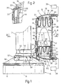
- Tube 7 is moved both ways along axis A by a pneumatic device 8, which comprises a hollow elongated casing 9 presenting an axis B parallel to axis A, and two pneumatic actuators 11 and 12.
- a pneumatic device 8 which comprises a hollow elongated casing 9 presenting an axis B parallel to axis A, and two pneumatic actuators 11 and 12.
- Each actuator 11, 12 comprises a deformable membrane 13, 14 made of elastomeric material, and which is bag-shaped when deformed - as shown by the dotted line for membrane 13 in Figure 1 - and forms a number of bends 15 when idle - as shown by the continuous lines in Figure 1.
- Actuators 11 and 12 also comprise respective identical plugging members 16 and 17, each of which forms a respective end portion of casing 9, and positively engages an intermediate cylindrical portion 9a of casing 9 extending coaxially with axis B.
- Each member 16, 17 grips a peripheral end portion of respective membrane 13, 14 against a respective end portion of portion 9a, and presents a curved asymmetrical projection 18, a flat flange 19 and a cylindrical portion 21.
- Portion 21 presents an outer annular groove 22 ( Figure 2) for airtight connection of respective membrane 13, 14 to portion 9a, so that a respective variable-volume chamber 23, 24 is formed between each membrane 13, 14 and respective member 16, 17.
- member 16 is positioned so that flange 19 grips a circular edge 26 of membrane 13 against an end edge 27 of portion 9a, which edge 27 is bent inwards to define an inner projection of portion 9a, and is located at annular groove 22 of member 16 so that membrane 13 is also gripped in airtight manner between edge 27 and groove 22.
- portion 9a comprises a cylindrical tubular body 29 coaxial with axis B, and terminates, at the end facing member 17, with a collar 30, which is connected integral with body 29 and presents an edge 32 similar in shape to edge 26 and bent inwards to define a respective inner projection.
- flange 19 of member 17 grips a circular edge 33 of membrane 14 against bent edge 32, which is located at annular groove 22 of member 17 so that membrane 14 is also gripped in airtight manner between edge 32 and groove 22.
- Each member 16, 17 also presents an outwardly-facing air nozzle 34 located at side 36 of curved projection 18; and each nozzle 34 is connected to a respective known pneumatic pushbutton 38, 39 (shown schematically in Figure 1) by a respective flexible conduit 37.
- pneumatic pushbuttons 38, 39 may be of any type, e.g. comprising a variable-volume air chamber defined, for example, by a bellows, and a known device for varying the volume of the air chamber.
- Control device 8 also comprises a movable connecting member in turn comprising a slide 41 connected to portion 9a so as to slide along axis B.
- slide 41 comprises a cylindrical wall 42 inside portion 9a, and a flat partition 43 connected integral with wall 42, extending inside wall 42, crosswise to axis B, between membranes 13 and 14, and which, in use, is moved both ways along axis B by membranes 13 and 14.
- Partition 43 presents three openings 44 to enable slide 41, in use, to move freely along axis B in the presence of any fluid inside casing 9.
- Slide 41 also comprises a cylindrical sector-shaped outer wall 46 coaxial with wall 42 and connected to wall 42 by a guide block 47, which is partly housed inside an axial slot 48 formed in portion 9a, parallel to axis B, and extending just short of collar 30, so that slide 41 is connected to portion 9a in axially-sliding, angular-fixed manner.
- Casing 9 also comprises two bottom arms 53 fitted with a substantially conical open collar 54, which engages an outer annular seat 57 formed on fixed body 6 of valve 5, between a wall 56 and an end flange 58. More specifically, collar 54 presents an inside diameter equal to that of seat 57, extends about an arc of over 180°, and presents radial slots 59 enabling it to expand elastically to snap inside seat 57.
- flexible conduits 37 of the required length are connected to respective nozzles 34; collar 54 is snapped inside seat 57 on wall 56 to connect casing 9 to fixed body 6 of discharge valve 5; fork 51 of slide 41 is snapped inside groove 52 on tube 7; and flexible conduits 37 are connected to respective pushbuttons 38, 39, which may be located to suit the user.
- pneumatic pushbutton 39 may be operated to feed air along respective conduit 37 into variable-volume chamber 24 and so distend membrane 14.
- Membrane 14 thus engages partition 43 from the top to move slide 41 gradually towards member 16; and fork 51 moves tube 7 back downwards to gradually close valve 5 and so cut off the outflow of water.
- Holes 44 in partition 43 of slide 41 obviously permit the fluid inside casing 9 to pass freely from one side to the other of partition 43 to prevent any impediment or delay in the movement of slide 41.
- device 8 operates both in the waterfree portion of the tank, i.e. in air, as well as in the portion of the tank normally filled with water, i.e. immersed in water. In the latter case, each time the tank is emptied completely, at least part of the water in casing 9 flows out through slot 48, and flows back in when further water is fed into the tank.
- pushbuttons 38 and 39 may be located to suit the user, even some distance from the tank and not necessarily close to each other.
- Pushbuttons 38, 39 and the particular arrangement of actuators 11, 12 in relation to slide 41 enable valve 5 to be opened or closed immediately in any intermediate operating condition, i.e. regardless of the position of slide 41 along axis B, thus greatly reducing water consumption.
- casing 9 may be formed differently from that described; and groove 52 may be formed further up tube 7, e.g. close to the top end of tube 7, so that device 8 operates in the waterfree portion of the tank.
- casing 9 may be fitted to any fixed part of the tank, as opposed to valve 5; and membranes 13, 14 may be formed differently from those described by way of example, and may be fitted to casing 9 other than as shown.
Landscapes
- Engineering & Computer Science (AREA)
- Health & Medical Sciences (AREA)
- Life Sciences & Earth Sciences (AREA)
- Hydrology & Water Resources (AREA)
- Public Health (AREA)
- Water Supply & Treatment (AREA)
- Mechanical Engineering (AREA)
- Aviation & Aerospace Engineering (AREA)
- Multiple-Way Valves (AREA)
- Mechanically-Actuated Valves (AREA)
- Portable Nailing Machines And Staplers (AREA)
- Fluid-Driven Valves (AREA)
- Sanitary Device For Flush Toilet (AREA)
- Self-Closing Valves And Venting Or Aerating Valves (AREA)
Claims (16)
- Dispositif pneumatique (8) pour actionner une soupape de vidange (5) d'un réservoir de chasse d'eau, le dispositif (8) comprenant un élément de liaison (41, 51) mobile le long d'un trajet donné (B) et relié solidairement à un élément mobile (7) de ladite soupape (5) ; et des premier (11) et second (12) actionneurs pneumatiques, qui agissent sur ledit élément de liaison (41, 51) pour déplacer l'élément de liaison (41, 51) dans des sens opposés le long dudit trajet (B) ; caractérisé en ce qu'il comprend des premier (38) et second (39) moyens de commande séparés pour commander sélectivement et indépendamment lesdits actionneurs pneumatiques (11) (12) quelle que soit la position de l'élément de liaison (41, 51) le long dudit trajet (B).
- Dispositif selon la revendication 1, caractérisé en ce qu'il comprend un boítier extérieur (9) ; et en ce que ledit élément de liaison (41, 51) comprend une portion formant pièce coulissante (41) logée à l'intérieur du boítier (9), et des moyens de guidage (48) associés au boítier (9) ; ladite portion formant pièce coulissante (41) étant reliée auxdits moyens de guidage (48) de façon à coulisser le long dudit trajet (B) .
- Dispositif selon la revendication 2, caractérisé en ce que lesdits actionneurs pneumatiques (11) 12) comprennent des chambres à volume variable correspondantes (23) (24), chacune d'elle communiquant avec un desdits premier et second moyens de commande (38) (39) ; chacune des chambres à volume variable (23) (24) étant définie par une portion d'extrémité correspondante (16) (17) dudit boítier (9) et par une membrane déformable élastiquement correspondante (13) (14).
- Dispositif selon la revendication 3, caractérisé en ce que lesdites membranes (13) (14) coopèrent directement en contact avec ledit élément de liaison (41, 51).
- Dispositif selon la revendication 3 ou 4, caractérisé en ce que chacune desdites membranes (13) (14) est pliée pour former un certain nombre de plis.
- Dispositif selon l'une des revendications précédentes 3 à 5, caractérisé en ce que ledit boítier (9) comprend une portion intermédiaire cylindrique (9a), et en ce que chaque dite membrane (13) (14) présente une portion périphérique correspondante saisie entre ladite portion intermédiaire (9a) et une desdites portions d'extrémité (16) (17) correspondante.
- Dispositif selon la revendication 6, caractérisé en ce que chacune desdites portions d'extrémité (16) (17) dudit boítier (9) comprend une portion cylindrique (21) présentant une gorge annulaire extérieure (22) ; chaque membrane (13) (14) étant forcée dans une desdites gorges annulaires extérieures (22) correspondante par une saillie annulaire intérieure correspondante (27) (32) sur ladite portion intermédiaire (9a).
- Dispositif selon la revendication 6 ou 7, caractérisé en ce que chacune desdites portions d'extrémité (16) (17) dudit boítier (9) présente un rebord annulaire extérieur (19) ; et chacune desdites membranes (13) (14) présente une portion périphérique (26) (33) saisie entre un desdits rebords (19) correspondant et un épaulement (27) (32) sur ladite portion intermédiaire (9a) .
- Dispositif selon la revendication 7, caractérisé en ce que ladite portion intermédiaire comprend deux corps tubulaires (30) (29) reliés solidairement l'un à l'autre, chacune desdites saillies annulaires intérieures (27) (32) étant supportée par un desdits corps tubulaires (30) (29) correspondant.
- Dispositif selon l'une des revendications précédentes 2 à 9, caractérisé en ce que ladite portion formant pièce coulissante (41) comprend une paroi cylindrique (42) reliée auxdits moyens de guidage (48) ; et une cloison transversale (43) formée d'une pièce avec ladite paroi cylindrique (42) et s'étendant transversalement audit trajet (B).
- Dispositif selon la revendication 9 ou 10, caractérisé en ce que lesdits moyens de guidage comprennent une fente (48) ménagée dans ledit boítier extérieur (9) parallèlement audit trajet (B) ; ladite portion formant pièce coulissante (41) comprenant une portion coulissante (47) s'engageant avec ladite fente (48) de façon coulissante.
- Dispositif selon la revendication 11, caractérisé en ce que l'élément de liaison (41) (51) 'comprend des moyens de liaison (51) qui s'encliquettent sur ledit élément mobile (7) de la soupape de vidange (5).
- Dispositif selon la revendication 12, caractérisé en ce que lesdits moyens de liaison comprennent une pièce fourchue (51) qui est reliée en venue de matière avec ladite portion coulissante (47) et qui s'encliquette dans une gorge annulaire (52) ménagée dans ledit élément mobile (7) de la soupape de vidange (5).
- Dispositif selon l'une des revendications précédentes 2 à 13, caractérisé en ce qu'il comprend d'autres moyens de liaison (54) pour relier de façon amovible ledit boítier (9) à un corps de support fixe (6).
- Dispositif selon la revendication 14, caractérisé en ce que lesdits autres moyens de liaison (54) sont des moyens de liaison par encliquetage.
- Dispositif selon la revendication 15, caractérisé en ce que lesdits moyens de liaison par encliquetage (54) comprennent une pièce fourchue élastique, qui s'engage directement dans une embase (57) formée sur un corps fixe (6) de ladite soupape de vidange (5).
Applications Claiming Priority (2)
| Application Number | Priority Date | Filing Date | Title |
|---|---|---|---|
| ITTO950660 | 1995-08-04 | ||
| IT95TO000660A IT1280896B1 (it) | 1995-08-04 | 1995-08-04 | Dispositivo pneumatico per l'azionamento di una valvola di scarico di una cassetta di risciacquo per wc |
Publications (2)
| Publication Number | Publication Date |
|---|---|
| EP0761893A1 EP0761893A1 (fr) | 1997-03-12 |
| EP0761893B1 true EP0761893B1 (fr) | 2000-12-06 |
Family
ID=11413769
Family Applications (1)
| Application Number | Title | Priority Date | Filing Date |
|---|---|---|---|
| EP96112459A Expired - Lifetime EP0761893B1 (fr) | 1995-08-04 | 1996-08-01 | Dispositif de commande pneumatique d'une soupape de vidange d'une chasse d'eau |
Country Status (6)
| Country | Link |
|---|---|
| EP (1) | EP0761893B1 (fr) |
| AT (1) | ATE197974T1 (fr) |
| DE (1) | DE69611130T2 (fr) |
| GR (1) | GR3035404T3 (fr) |
| IT (1) | IT1280896B1 (fr) |
| PT (1) | PT761893E (fr) |
Families Citing this family (7)
| Publication number | Priority date | Publication date | Assignee | Title |
|---|---|---|---|---|
| DE29808200U1 (de) * | 1997-07-07 | 1998-07-23 | Geberit Technik Ag, Jona | Betätigungsvorrichtung für ein Ablaufventil eines WC-Spülkastens |
| ATE242371T1 (de) * | 1997-12-15 | 2003-06-15 | Geberit Technik Ag | Vorrichtung zur pneumatischen betätigung eines spülkastens |
| ITMI20031325A1 (it) * | 2003-06-27 | 2004-12-28 | Valsir Spa | Dispositivo pneumatico di azionamento del gruppo valvola di scarico di una cassetta di risciacquo. |
| DE10330324A1 (de) * | 2003-07-04 | 2005-01-20 | Grohe Water Technology Ag & Co. Kg | Ablaufventil mit Servomotor |
| ITMI20040044A1 (it) * | 2004-01-15 | 2004-04-15 | Valsir Spa | Dispositivo di azionamento dello scarico in una cassetta di risciacquo |
| CN103883783B (zh) * | 2012-12-21 | 2017-08-04 | 厦门威迪亚科技有限公司 | 一种气动排水阀的气动感应控制装置 |
| DE102024106325A1 (de) * | 2024-03-05 | 2025-09-11 | Grohe Ag | Vorrichtung zur Betätigung einer Spülung eines WCs und Spülung für ein WC |
Family Cites Families (3)
| Publication number | Priority date | Publication date | Assignee | Title |
|---|---|---|---|---|
| NL8301009A (nl) * | 1983-03-21 | 1984-10-16 | Simmonds Precision N V | Stortbak van het laaghangende type. |
| US4809367A (en) * | 1986-08-08 | 1989-03-07 | Partall Systems (Proprietary) Limited | Cistern flushing apparatus |
| DE3729569A1 (de) * | 1987-09-04 | 1989-03-16 | Schwab Sanitaer Plastic Gmbh | Spuelkasten |
-
1995
- 1995-08-04 IT IT95TO000660A patent/IT1280896B1/it active IP Right Grant
-
1996
- 1996-08-01 AT AT96112459T patent/ATE197974T1/de not_active IP Right Cessation
- 1996-08-01 EP EP96112459A patent/EP0761893B1/fr not_active Expired - Lifetime
- 1996-08-01 PT PT96112459T patent/PT761893E/pt unknown
- 1996-08-01 DE DE69611130T patent/DE69611130T2/de not_active Expired - Fee Related
-
2001
- 2001-02-13 GR GR20010400232T patent/GR3035404T3/el not_active IP Right Cessation
Also Published As
| Publication number | Publication date |
|---|---|
| EP0761893A1 (fr) | 1997-03-12 |
| DE69611130T2 (de) | 2001-05-23 |
| GR3035404T3 (en) | 2001-05-31 |
| ITTO950660A1 (it) | 1997-02-04 |
| DE69611130D1 (de) | 2001-01-11 |
| PT761893E (pt) | 2001-04-30 |
| ITTO950660A0 (it) | 1995-08-04 |
| ATE197974T1 (de) | 2000-12-15 |
| IT1280896B1 (it) | 1998-02-11 |
Similar Documents
| Publication | Publication Date | Title |
|---|---|---|
| EP0761893B1 (fr) | Dispositif de commande pneumatique d'une soupape de vidange d'une chasse d'eau | |
| US4108202A (en) | Ball cock having vertically adjustable outlet tube | |
| EP1078187B1 (fr) | Soupape de gaz et procede d'acheminement d'un debit gazeux | |
| US10941551B2 (en) | Drain valve for a sanitary cistern | |
| EP0006024A1 (fr) | Procédé et dispositif pour la traite des animaux | |
| FI117298B (fi) | Alipaineviemärijärjestelmä | |
| MX2007006306A (es) | Valvula de limpieza automatica con derivacion doble tipo piston. | |
| US4186765A (en) | Liquid level control valve assembly | |
| EP1267979A1 (fr) | Dispositif de valve | |
| US5408709A (en) | Shower control assembly | |
| US7028704B2 (en) | Fill valve | |
| US6478044B2 (en) | Snap-action piloted fill valve | |
| KR20020045504A (ko) | 수세식 변기용 용량 제어장치 | |
| JPH02253068A (ja) | 多段式フローコントロール装置 | |
| EP0945687B1 (fr) | Vanne de dérivation actionnée par pression | |
| JPH09111838A (ja) | ボールタップ装置 | |
| SU1674069A1 (ru) | Устройство дл регулировани уровн воды в бьефах гидротехнических сооружений | |
| SU1348783A1 (ru) | Устройство дл регулировани уровн воды в бьефах гидротехнических сооружений | |
| GB2039345A (en) | An improvement in or relating to float valves | |
| US20260044160A1 (en) | Pressure reducing valve, and bidet and water purifier comprising same | |
| EP1364144B1 (fr) | Dispositif de regulation du debit de liquide commande par flotteur | |
| EP1199502A3 (fr) | Soupape de remplissage à bruit faible pour une chasse d'eau | |
| EP1491691A2 (fr) | Dispositif pneumatique d'activation d'une vanne de vidange d'un réservoir de chasse d'eau | |
| US20160290527A1 (en) | Hydraulic valve adapter | |
| JPH09100921A (ja) | 浴槽用リフトの手動制御ユニット |
Legal Events
| Date | Code | Title | Description |
|---|---|---|---|
| PUAI | Public reference made under article 153(3) epc to a published international application that has entered the european phase |
Free format text: ORIGINAL CODE: 0009012 |
|
| AK | Designated contracting states |
Kind code of ref document: A1 Designated state(s): AT CH DE FR GR IT LI LU NL PT |
|
| 17P | Request for examination filed |
Effective date: 19970729 |
|
| RAP1 | Party data changed (applicant data changed or rights of an application transferred) |
Owner name: VALSIR S.P.A. |
|
| GRAG | Despatch of communication of intention to grant |
Free format text: ORIGINAL CODE: EPIDOS AGRA |
|
| 17Q | First examination report despatched |
Effective date: 19991020 |
|
| GRAG | Despatch of communication of intention to grant |
Free format text: ORIGINAL CODE: EPIDOS AGRA |
|
| GRAH | Despatch of communication of intention to grant a patent |
Free format text: ORIGINAL CODE: EPIDOS IGRA |
|
| GRAH | Despatch of communication of intention to grant a patent |
Free format text: ORIGINAL CODE: EPIDOS IGRA |
|
| GRAA | (expected) grant |
Free format text: ORIGINAL CODE: 0009210 |
|
| AK | Designated contracting states |
Kind code of ref document: B1 Designated state(s): AT CH DE FR GR IT LI LU NL PT |
|
| REF | Corresponds to: |
Ref document number: 197974 Country of ref document: AT Date of ref document: 20001215 Kind code of ref document: T |
|
| REG | Reference to a national code |
Ref country code: CH Ref legal event code: EP |
|
| REF | Corresponds to: |
Ref document number: 69611130 Country of ref document: DE Date of ref document: 20010111 |
|
| ITF | It: translation for a ep patent filed | ||
| REG | Reference to a national code |
Ref country code: CH Ref legal event code: NV Representative=s name: ISLER & PEDRAZZINI AG |
|
| ET | Fr: translation filed | ||
| REG | Reference to a national code |
Ref country code: PT Ref legal event code: SC4A Free format text: AVAILABILITY OF NATIONAL TRANSLATION Effective date: 20010131 |
|
| PLBE | No opposition filed within time limit |
Free format text: ORIGINAL CODE: 0009261 |
|
| STAA | Information on the status of an ep patent application or granted ep patent |
Free format text: STATUS: NO OPPOSITION FILED WITHIN TIME LIMIT |
|
| 26N | No opposition filed | ||
| PGFP | Annual fee paid to national office [announced via postgrant information from national office to epo] |
Ref country code: LU Payment date: 20040722 Year of fee payment: 9 |
|
| PGFP | Annual fee paid to national office [announced via postgrant information from national office to epo] |
Ref country code: GR Payment date: 20040727 Year of fee payment: 9 |
|
| PGFP | Annual fee paid to national office [announced via postgrant information from national office to epo] |
Ref country code: PT Payment date: 20040729 Year of fee payment: 9 |
|
| PGFP | Annual fee paid to national office [announced via postgrant information from national office to epo] |
Ref country code: AT Payment date: 20040730 Year of fee payment: 9 |
|
| PGFP | Annual fee paid to national office [announced via postgrant information from national office to epo] |
Ref country code: FR Payment date: 20040817 Year of fee payment: 9 |
|
| PGFP | Annual fee paid to national office [announced via postgrant information from national office to epo] |
Ref country code: CH Payment date: 20040818 Year of fee payment: 9 |
|
| PGFP | Annual fee paid to national office [announced via postgrant information from national office to epo] |
Ref country code: NL Payment date: 20040831 Year of fee payment: 9 |
|
| PGFP | Annual fee paid to national office [announced via postgrant information from national office to epo] |
Ref country code: DE Payment date: 20041028 Year of fee payment: 9 |
|
| PG25 | Lapsed in a contracting state [announced via postgrant information from national office to epo] |
Ref country code: LU Free format text: LAPSE BECAUSE OF NON-PAYMENT OF DUE FEES Effective date: 20050801 Ref country code: IT Free format text: LAPSE BECAUSE OF NON-PAYMENT OF DUE FEES;WARNING: LAPSES OF ITALIAN PATENTS WITH EFFECTIVE DATE BEFORE 2007 MAY HAVE OCCURRED AT ANY TIME BEFORE 2007. THE CORRECT EFFECTIVE DATE MAY BE DIFFERENT FROM THE ONE RECORDED. Effective date: 20050801 Ref country code: AT Free format text: LAPSE BECAUSE OF NON-PAYMENT OF DUE FEES Effective date: 20050801 |
|
| PG25 | Lapsed in a contracting state [announced via postgrant information from national office to epo] |
Ref country code: LI Free format text: LAPSE BECAUSE OF NON-PAYMENT OF DUE FEES Effective date: 20050831 Ref country code: CH Free format text: LAPSE BECAUSE OF NON-PAYMENT OF DUE FEES Effective date: 20050831 |
|
| PG25 | Lapsed in a contracting state [announced via postgrant information from national office to epo] |
Ref country code: PT Free format text: LAPSE BECAUSE OF NON-PAYMENT OF DUE FEES Effective date: 20060201 |
|
| PG25 | Lapsed in a contracting state [announced via postgrant information from national office to epo] |
Ref country code: NL Free format text: LAPSE BECAUSE OF NON-PAYMENT OF DUE FEES Effective date: 20060301 Ref country code: DE Free format text: LAPSE BECAUSE OF NON-PAYMENT OF DUE FEES Effective date: 20060301 |
|
| PG25 | Lapsed in a contracting state [announced via postgrant information from national office to epo] |
Ref country code: GR Free format text: LAPSE BECAUSE OF NON-PAYMENT OF DUE FEES Effective date: 20060302 |
|
| REG | Reference to a national code |
Ref country code: CH Ref legal event code: PL |
|
| PG25 | Lapsed in a contracting state [announced via postgrant information from national office to epo] |
Ref country code: FR Free format text: LAPSE BECAUSE OF NON-PAYMENT OF DUE FEES Effective date: 20060428 |
|
| NLV4 | Nl: lapsed or anulled due to non-payment of the annual fee |
Effective date: 20060301 |
|
| REG | Reference to a national code |
Ref country code: FR Ref legal event code: ST Effective date: 20060428 |