EP0762417A2 - Signalaufzeichung und -wiedergabe, Signalaufzeichnungsmedium sowie Signalübertragung und -empfang - Google Patents
Signalaufzeichung und -wiedergabe, Signalaufzeichnungsmedium sowie Signalübertragung und -empfang Download PDFInfo
- Publication number
- EP0762417A2 EP0762417A2 EP96306006A EP96306006A EP0762417A2 EP 0762417 A2 EP0762417 A2 EP 0762417A2 EP 96306006 A EP96306006 A EP 96306006A EP 96306006 A EP96306006 A EP 96306006A EP 0762417 A2 EP0762417 A2 EP 0762417A2
- Authority
- EP
- European Patent Office
- Prior art keywords
- signal
- signals
- video signals
- audio signals
- identification signal
- Prior art date
- Legal status (The legal status is an assumption and is not a legal conclusion. Google has not performed a legal analysis and makes no representation as to the accuracy of the status listed.)
- Granted
Links
Images


Classifications
-
- G—PHYSICS
- G11—INFORMATION STORAGE
- G11B—INFORMATION STORAGE BASED ON RELATIVE MOVEMENT BETWEEN RECORD CARRIER AND TRANSDUCER
- G11B20/00—Signal processing not specific to the method of recording or reproducing; Circuits therefor
- G11B20/10—Digital recording or reproducing
-
- H—ELECTRICITY
- H04—ELECTRIC COMMUNICATION TECHNIQUE
- H04N—PICTORIAL COMMUNICATION, e.g. TELEVISION
- H04N21/00—Selective content distribution, e.g. interactive television or video on demand [VOD]
- H04N21/80—Generation or processing of content or additional data by content creator independently of the distribution process; Content per se
- H04N21/83—Generation or processing of protective or descriptive data associated with content; Content structuring
- H04N21/835—Generation of protective data, e.g. certificates
- H04N21/8358—Generation of protective data, e.g. certificates involving watermark
-
- G—PHYSICS
- G11—INFORMATION STORAGE
- G11B—INFORMATION STORAGE BASED ON RELATIVE MOVEMENT BETWEEN RECORD CARRIER AND TRANSDUCER
- G11B20/00—Signal processing not specific to the method of recording or reproducing; Circuits therefor
- G11B20/00086—Circuits for prevention of unauthorised reproduction or copying, e.g. piracy
- G11B20/00094—Circuits for prevention of unauthorised reproduction or copying, e.g. piracy involving measures which result in a restriction to authorised record carriers
- G11B20/00115—Circuits for prevention of unauthorised reproduction or copying, e.g. piracy involving measures which result in a restriction to authorised record carriers wherein the record carrier stores a unique medium identifier
-
- G—PHYSICS
- G11—INFORMATION STORAGE
- G11B—INFORMATION STORAGE BASED ON RELATIVE MOVEMENT BETWEEN RECORD CARRIER AND TRANSDUCER
- G11B20/00—Signal processing not specific to the method of recording or reproducing; Circuits therefor
- G11B20/00086—Circuits for prevention of unauthorised reproduction or copying, e.g. piracy
- G11B20/00094—Circuits for prevention of unauthorised reproduction or copying, e.g. piracy involving measures which result in a restriction to authorised record carriers
- G11B20/00123—Circuits for prevention of unauthorised reproduction or copying, e.g. piracy involving measures which result in a restriction to authorised record carriers the record carrier being identified by recognising some of its unique characteristics, e.g. a unique defect pattern serving as a physical signature of the record carrier
-
- G—PHYSICS
- G11—INFORMATION STORAGE
- G11B—INFORMATION STORAGE BASED ON RELATIVE MOVEMENT BETWEEN RECORD CARRIER AND TRANSDUCER
- G11B20/00—Signal processing not specific to the method of recording or reproducing; Circuits therefor
- G11B20/00086—Circuits for prevention of unauthorised reproduction or copying, e.g. piracy
- G11B20/00166—Circuits for prevention of unauthorised reproduction or copying, e.g. piracy involving measures which result in a restriction to authorised contents recorded on or reproduced from a record carrier, e.g. music or software
- G11B20/00181—Circuits for prevention of unauthorised reproduction or copying, e.g. piracy involving measures which result in a restriction to authorised contents recorded on or reproduced from a record carrier, e.g. music or software using a content identifier, e.g. an international standard recording code [ISRC] or a digital object identifier [DOI]
-
- G—PHYSICS
- G11—INFORMATION STORAGE
- G11B—INFORMATION STORAGE BASED ON RELATIVE MOVEMENT BETWEEN RECORD CARRIER AND TRANSDUCER
- G11B20/00—Signal processing not specific to the method of recording or reproducing; Circuits therefor
- G11B20/00086—Circuits for prevention of unauthorised reproduction or copying, e.g. piracy
- G11B20/00681—Circuits for prevention of unauthorised reproduction or copying, e.g. piracy involving measures which prevent a specific kind of data access
- G11B20/00688—Circuits for prevention of unauthorised reproduction or copying, e.g. piracy involving measures which prevent a specific kind of data access said measures preventing that a usable copy of recorded data can be made on another medium
-
- G—PHYSICS
- G11—INFORMATION STORAGE
- G11B—INFORMATION STORAGE BASED ON RELATIVE MOVEMENT BETWEEN RECORD CARRIER AND TRANSDUCER
- G11B20/00—Signal processing not specific to the method of recording or reproducing; Circuits therefor
- G11B20/00086—Circuits for prevention of unauthorised reproduction or copying, e.g. piracy
- G11B20/00884—Circuits for prevention of unauthorised reproduction or copying, e.g. piracy involving a watermark, i.e. a barely perceptible transformation of the original data which can nevertheless be recognised by an algorithm
- G11B20/00891—Circuits for prevention of unauthorised reproduction or copying, e.g. piracy involving a watermark, i.e. a barely perceptible transformation of the original data which can nevertheless be recognised by an algorithm embedded in audio data
-
- G—PHYSICS
- G11—INFORMATION STORAGE
- G11B—INFORMATION STORAGE BASED ON RELATIVE MOVEMENT BETWEEN RECORD CARRIER AND TRANSDUCER
- G11B27/00—Editing; Indexing; Addressing; Timing or synchronising; Monitoring; Measuring tape travel
- G11B27/10—Indexing; Addressing; Timing or synchronising; Measuring tape travel
- G11B27/19—Indexing; Addressing; Timing or synchronising; Measuring tape travel by using information detectable on the record carrier
- G11B27/28—Indexing; Addressing; Timing or synchronising; Measuring tape travel by using information detectable on the record carrier by using information signals recorded by the same method as the main recording
- G11B27/30—Indexing; Addressing; Timing or synchronising; Measuring tape travel by using information detectable on the record carrier by using information signals recorded by the same method as the main recording on the same track as the main recording
- G11B27/3027—Indexing; Addressing; Timing or synchronising; Measuring tape travel by using information detectable on the record carrier by using information signals recorded by the same method as the main recording on the same track as the main recording used signal is digitally coded
-
- G—PHYSICS
- G11—INFORMATION STORAGE
- G11B—INFORMATION STORAGE BASED ON RELATIVE MOVEMENT BETWEEN RECORD CARRIER AND TRANSDUCER
- G11B27/00—Editing; Indexing; Addressing; Timing or synchronising; Monitoring; Measuring tape travel
- G11B27/10—Indexing; Addressing; Timing or synchronising; Measuring tape travel
- G11B27/19—Indexing; Addressing; Timing or synchronising; Measuring tape travel by using information detectable on the record carrier
- G11B27/28—Indexing; Addressing; Timing or synchronising; Measuring tape travel by using information detectable on the record carrier by using information signals recorded by the same method as the main recording
- G11B27/32—Indexing; Addressing; Timing or synchronising; Measuring tape travel by using information detectable on the record carrier by using information signals recorded by the same method as the main recording on separate auxiliary tracks of the same or an auxiliary record carrier
- G11B27/327—Table of contents
- G11B27/329—Table of contents on a disc [VTOC]
-
- H—ELECTRICITY
- H04—ELECTRIC COMMUNICATION TECHNIQUE
- H04N—PICTORIAL COMMUNICATION, e.g. TELEVISION
- H04N21/00—Selective content distribution, e.g. interactive television or video on demand [VOD]
- H04N21/20—Servers specifically adapted for the distribution of content, e.g. VOD servers; Operations thereof
- H04N21/23—Processing of content or additional data; Elementary server operations; Server middleware
- H04N21/238—Interfacing the downstream path of the transmission network, e.g. adapting the transmission rate of a video stream to network bandwidth; Processing of multiplex streams
- H04N21/2389—Multiplex stream processing, e.g. multiplex stream encrypting
- H04N21/23892—Multiplex stream processing, e.g. multiplex stream encrypting involving embedding information at multiplex stream level, e.g. embedding a watermark at packet level
-
- H—ELECTRICITY
- H04—ELECTRIC COMMUNICATION TECHNIQUE
- H04N—PICTORIAL COMMUNICATION, e.g. TELEVISION
- H04N5/00—Details of television systems
- H04N5/76—Television signal recording
- H04N5/91—Television signal processing therefor
- H04N5/913—Television signal processing therefor for scrambling ; for copy protection
-
- G—PHYSICS
- G06—COMPUTING OR CALCULATING; COUNTING
- G06F—ELECTRIC DIGITAL DATA PROCESSING
- G06F2211/00—Indexing scheme relating to details of data-processing equipment not covered by groups G06F3/00 - G06F13/00
- G06F2211/007—Encryption, En-/decode, En-/decipher, En-/decypher, Scramble, (De-)compress
-
- G—PHYSICS
- G11—INFORMATION STORAGE
- G11B—INFORMATION STORAGE BASED ON RELATIVE MOVEMENT BETWEEN RECORD CARRIER AND TRANSDUCER
- G11B2220/00—Record carriers by type
- G11B2220/20—Disc-shaped record carriers
- G11B2220/25—Disc-shaped record carriers characterised in that the disc is based on a specific recording technology
- G11B2220/2537—Optical discs
- G11B2220/2545—CDs
-
- G—PHYSICS
- G11—INFORMATION STORAGE
- G11B—INFORMATION STORAGE BASED ON RELATIVE MOVEMENT BETWEEN RECORD CARRIER AND TRANSDUCER
- G11B2220/00—Record carriers by type
- G11B2220/20—Disc-shaped record carriers
- G11B2220/25—Disc-shaped record carriers characterised in that the disc is based on a specific recording technology
- G11B2220/2537—Optical discs
- G11B2220/2562—DVDs [digital versatile discs]; Digital video discs; MMCDs; HDCDs
-
- G—PHYSICS
- G11—INFORMATION STORAGE
- G11B—INFORMATION STORAGE BASED ON RELATIVE MOVEMENT BETWEEN RECORD CARRIER AND TRANSDUCER
- G11B7/00—Recording or reproducing by optical means, e.g. recording using a thermal beam of optical radiation by modifying optical properties or the physical structure, reproducing using an optical beam at lower power by sensing optical properties; Record carriers therefor
- G11B7/007—Arrangement of the information on the record carrier, e.g. form of tracks, actual track shape, e.g. wobbled, or cross-section, e.g. v-shaped; Sequential information structures, e.g. sectoring or header formats within a track
- G11B7/00736—Auxiliary data, e.g. lead-in, lead-out, Power Calibration Area [PCA], Burst Cutting Area [BCA], control information
-
- H—ELECTRICITY
- H04—ELECTRIC COMMUNICATION TECHNIQUE
- H04N—PICTORIAL COMMUNICATION, e.g. TELEVISION
- H04N5/00—Details of television systems
- H04N5/76—Television signal recording
- H04N5/91—Television signal processing therefor
- H04N5/913—Television signal processing therefor for scrambling ; for copy protection
- H04N2005/91307—Television signal processing therefor for scrambling ; for copy protection by adding a copy protection signal to the video signal
- H04N2005/91335—Television signal processing therefor for scrambling ; for copy protection by adding a copy protection signal to the video signal the copy protection signal being a watermark
-
- H—ELECTRICITY
- H04—ELECTRIC COMMUNICATION TECHNIQUE
- H04N—PICTORIAL COMMUNICATION, e.g. TELEVISION
- H04N5/00—Details of television systems
- H04N5/76—Television signal recording
- H04N5/91—Television signal processing therefor
- H04N5/913—Television signal processing therefor for scrambling ; for copy protection
- H04N2005/91307—Television signal processing therefor for scrambling ; for copy protection by adding a copy protection signal to the video signal
- H04N2005/91342—Television signal processing therefor for scrambling ; for copy protection by adding a copy protection signal to the video signal the copy protection signal being an authentication signal
-
- H—ELECTRICITY
- H04—ELECTRIC COMMUNICATION TECHNIQUE
- H04N—PICTORIAL COMMUNICATION, e.g. TELEVISION
- H04N5/00—Details of television systems
- H04N5/76—Television signal recording
- H04N5/91—Television signal processing therefor
- H04N5/913—Television signal processing therefor for scrambling ; for copy protection
- H04N2005/91357—Television signal processing therefor for scrambling ; for copy protection by modifying the video signal
- H04N2005/91364—Television signal processing therefor for scrambling ; for copy protection by modifying the video signal the video signal being scrambled
-
- H—ELECTRICITY
- H04—ELECTRIC COMMUNICATION TECHNIQUE
- H04N—PICTORIAL COMMUNICATION, e.g. TELEVISION
- H04N5/00—Details of television systems
- H04N5/76—Television signal recording
- H04N5/84—Television signal recording using optical recording
- H04N5/85—Television signal recording using optical recording on discs or drums
-
- H—ELECTRICITY
- H04—ELECTRIC COMMUNICATION TECHNIQUE
- H04N—PICTORIAL COMMUNICATION, e.g. TELEVISION
- H04N9/00—Details of colour television systems
- H04N9/79—Processing of colour television signals in connection with recording
- H04N9/7921—Processing of colour television signals in connection with recording for more than one processing mode
-
- H—ELECTRICITY
- H04—ELECTRIC COMMUNICATION TECHNIQUE
- H04N—PICTORIAL COMMUNICATION, e.g. TELEVISION
- H04N9/00—Details of colour television systems
- H04N9/79—Processing of colour television signals in connection with recording
- H04N9/80—Transformation of the television signal for recording, e.g. modulation, frequency changing; Inverse transformation for playback
- H04N9/804—Transformation of the television signal for recording, e.g. modulation, frequency changing; Inverse transformation for playback involving pulse code modulation of the colour picture signal components
- H04N9/8042—Transformation of the television signal for recording, e.g. modulation, frequency changing; Inverse transformation for playback involving pulse code modulation of the colour picture signal components involving data reduction
Definitions
- This invention relates to signal recording/reproducing methods and apparatus for recording/reproducing signals on or from signal record (recording, recordable or recorded) media, signal record media having signals recorded thereon, and signal transmitting/receiving methods and apparatus for transmitting/receiving signals.
- signal record medium for recording information signals such as speech or various sorts of data
- signal record medium for optically recording the information signals such as a compact disc for music or a CD-ROM employing the CD disc standard for data
- DVD digital video disc
- the entire audio or video signals, for example, recorded on the signal record medium, such as CD, CD-ROM or DAD, may be read out by a reproducing apparatus and duplicated on another signal record medium capable of signal recording and reproduction, such as a hard disc, and the data thus copied on the hard disc may then be supplied to an encoder system for the CD, CD-ROM or DAD for formulating a new CD, CD-ROM or DAD, in order to prepare a CD, CD-ROM or a DAD having recorded thereon the same signals as those recorded on the original signal record medium.
- an identification signal relevant to the video signals and/or the audio signals is inserted as a portion of the video signals and/or the audio signals in a configuration of reducing the effect on the video signals and/or the audio signals, and the video signals and/or the audio signals, into which has been inserted the identification signal, are recorded on a signal record medium or transmitted over a signal transmission medium.
- video signals and/or the audio signals reproduced from a signal record medium or transmitted over a signal transmission medium are received, and an identification signal, inserted as a portion of the video signals and/or the audio signals, is detected from the reproduced or received signals.
- a signal record medium has recorded thereon signals comprised of video signals and/or audio signals and an identification signal which is relevant to the video signals and/or the audio signals and which has been inserted as a portion of the video signals and/or the audio signals in a configuration of reducing the effect on the video signals and/or the audio signals.
- a meaningful identification signal is added to video signals and/or audio signals themselves in order to permit identification of these signals. That is, an identification signal relevant to the video signals and/or the audio signals is inserted as a portion of the video signals and/or the audio signals in a configuration of reducing the effect on the video signals and/or the audio signals, and the video signals and/or the audio signals, in which the identification signal has been inserted as an ancillary signal, are recorded on a signal record medium or transmitted over a transmission medium.
- the identification signal thus added to the video signals and/or the audio signals, is effective to prevent unauthorized copying.
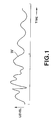
- Fig. 1 illustrates a typical waveform of audio signals.
- Fig.2 illustrates an embodiment in which an identification signal is appended to the least significant bit (LSB) of a 1-sample-16-bit time domain audio PCM signals.
- LSB least significant bit
- Fig.3 shows an arbitrary pixel in a frame to which is appended an identification signal.
- Fig.4 is a block circuit diagram showing an arrangement of an illustrative signal recording apparatus and an illustrative signal reproducing apparatus.
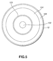
- Fig.5 shows an optical disc as an example of a signal record medium.
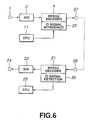
- Fig.6 is a block circuit diagram showing an example of appending an identification signal during encoding for data compression.
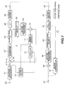
- Fig.7 is a block circuit diagram showing an illustrative arrangement of an encoding circuit for compression.
- Fig.8 illustrates a sequence interchanging operation.
- Fig.9 is a block circuit diagram showing an arrangement of appending an identification signal to a video signal in an analog stage.
- Fig.10 is a block circuit diagram showing an arrangement of appending an identification signal to an audio signal in an analog stage.
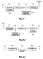
- Fig.11 is a schematic block circuit diagram showing an arrangement of a transmission apparatus.
- Fig.12 is a schematic block circuit diagram showing an arrangement of a reception apparatus.
- Fig.13 is a block circuit diagram showing essential portions of signal transmission/ reception over a transmission channel.
- an identification signal pertinent to a video signal and/or an audio signal is inserted as a part of the video signal and/or the audio signal in a configuration of reducing the effect on the video signal and/or the audio signal.
- time-domain data such as music signals
- LSBs least significant bits
- the audio signal waveform W as shown in Fig.1 is sampled and quantized to 1-sample-16-bit time domain audio PCM signals shown for example in Fig.2, the least significant bits (LSBs) of the 1-sample-16-bit time domain audio PCM signals are handled statistically.
- LSBs least significant bits
- the state biased to "1” or “0” may be created by compulsorily increasing "1” or "0" in the LSBs of the sample data of the original signals for detection.
- the LSBs of the audio PCM signals of the respective samples are set for example to "0", irrespective of whether the time interval is synchronous or non-synchronous, the number of "0"s is statistically increased, with the number of "1”s being decreased. Conversely, if the LSBs are set to "1", the number of "1”s is statistically increased, with the number of "0”s being decreased. Thus it becomes possible to represent one bit of the pertinent identification signal.
- the LSBs of the continuous 1,000 samples may compulsorily be set to "1" or "0". Although this simplifies detection, the LSBs of 16-bit samples are used contiguously, the effective bits become 15 bits, thus deteriorating the signal. In addition, the signal tends to be altered.
- arbitrary 200 of 1000 consecutive samples compulsorily to "1" or "0".
- These arbitrary 200 samples may be consecutive in an arbitrary position in the 1,000 samples, or may be at discontinuous random positions. If the samples are contiguous, they can be detected easily. However, the risk of signal deterioration and alteration becomes higher.
- the LSBs of the remaining 800 samples may be approximated to the normal distribution. For example, if “1”s are introduced into the 200 samples, the number of “1”s in the LSBs of the remaining 800 samples, if fluctuated, is comprised substantially in 400 ⁇ 40. If 200 "1"s are added, the number of “1”s of the LSBs of the 1,000 samples is 600 ⁇ 40, with the level of significance being 0.01%. It may thus be seen that 1 bit of the identification signal is "1". Similarly, by inserting "0" into the LSBs of the 200 samples, the 1 bit of the identification signal may be associated with "0". By compulsorily setting the LSBs of the arbitrary 200 samples to "1" or "0” every 1,000 samples of the audio PCM signals as main data, "1"s or "0”s of the identification signals can be sequentially embedded in the main data itself.
- the LSBs of the 200 samples are compulsorily set to "1"s or "0"s at an interval of 5 samples of the 1,000 samples.
- the effect is small as compared to the case of embedding in LSBs of contiguous 200 samples.
- the number of "1"s or "0"s of the LSBs of the 1,000 samples may be counted.
- the 5-sample period count may be performed in parallel for five series of different phases to find out a series where drastic bias exists.
- the LSBs may be compulsorily set to "1"s or "0"s at an arbitrary sample period such as 10 sample period. If the period is 10 samples, the LSBs of the 100 samples are modified in the 1,000 samples. However, by counting the number of "1"s and “0"s of the LSBs of 10 series of different phases at 10-sample periods, the totality of 100 samples are detected as "1" or "0" so long as there is no error, thus assuring high reliability.
- identification signals it is also possible to embed plural sorts of identification signals in parallel. If the total number of samples handled statistically is 1,000, and "1"s or "0"s are compulsorily inserted at a period of 50 samples, plural sorts of identification signals can be inserted at different phases in the 50-sample period. If, as a specified example, five sorts (channels) of the identification signals are embedded in different phases, and these five sorts are embedded at equal intervals, the LSBs are compulsorily set to "1"s or "0"s at a period of 10 samples. For detection, LSBs of the 50 different sample series having different phases are counted at 50 sample periods and a series in which only "1"s or "0"s are contiguously detected may be used as an identification signal. Of course, the number of samples or the number of sample periods are not limited to 1000 samples or 50 samples, respectively.
- the LSBs of the samples may also be conceived to handle the LSBs of the samples at periodic positions in the sample series. That is, of 1,000 16-bit samples of the audio PCM signals, sequentially taken out at, for example, five samples as a period, 200 samples, may be arbitrarily taken out and compulsorily set to "1"s or "0"s. In this case, the 1 bit of the identification information is distributed in a range of contiguous 5,000 samples of the original PCM data. Of the 1,000 samples of the 5-sample periods in the 5,000 samples, 200 samples may be selected by taking 200 consecutive samples, random 200 samples or 200 samples at a 5-sample period (the period being 25 samples for the entire samples).
- statistic bias may be enlarged by modifying to "1"s only "0"s of the LSBs of the original data.
- the LSBs of the audio PCM signal samples are set to, for example, "0", at a pre-set time interval, whether synchronously or asynchronously, the number of "0"s is statistically increased and the number of "1”s is correspondingly decreased, whereas, if the LSBs are set to "1" in the same manner, the number of "1”s is statistically increased and the number of "0”s is correspondingly decreased.
- the LSBs for example, of respective audio PCM samples are set to "0"s or "1"s at a pre-set time interval, it becomes possible to insert an identification signal represented by one bit of "0" or "1" in the above-mentioned 1-sample-16-bit audio PCM signals.
- the above pre-set time interval is preferably set so as not to produce alien hearing feeling even if the "0"s or "1"s are inserted in the LSBs.
- an identification signal made up of noise-like "0"s and "1"s having meaning in a certain time interval in, for example, the LSBs of respective samples in the pre-set time interval. If the LSBs of the respective samples are read with the above time intervals as units, it becomes possible to take out the identification signals from the LSBs in the respective samples in the time interval. If the contents of the identification signal to be inserted into the above LSBs are modified at the above-mentioned time interval, it becomes possible to insert plural sorts of identification signals. It is however desirable to use the noise-like information as the plural sorts of the identification signals in order to minimize adverse psychoacoustic effects.
- the identification signal may be inserted into bits other than the LSBs. In the case of audio signals, ill effects on the acoustic sense may be minimized by inserting the identification signal in the LSBs. Therefore, the identification signal is inserted in the present embodiment in the LSBs.
- the identification signal is inserted in the LSBs in low signal level (signal energy) portions of audio signals, there is a risk that addition of an identification signal even in the LSB produces outstanding alien psychoacoustic feeling.
- the signal level corresponds to 15 bits in terms of an absolute value level
- a range from 0 to 32767 may be represented, of which the MSB corresponds to 16384 and the LSB corresponds to 1.
- the LSB is intentionally modified for addition of the identification signal, and if the original signal level is 25000, for example, the effect of intentional change of the LSB is small. However, if the original signal level is 10, for example, the effect of intentionally changing the LSB is no longer negligible.
- the identification signal For avoiding such ill effect on the psychoacoustic sense, it is also possible to add the identification signal only to the LSBs in the high signal level (signal energy) portion. In such case, it becomes necessary to detect a high signal level portion and to add the identification signal to the LSBs only in such high signal level portion. This can be achieved by operating on the LSB only when "1" is set in, for example, the MSB.
- the masking effect on the time axis that is the effect of the low signal level portion being masked by the high signal level portion, is in operation, so that addition of the identification signal can be done only in the masked portion.
- time-domain audio signals are orthogonal-transformed into frequency-domain signals (frequency components) which are quantized
- the masking effect on the frequency axis that is the effect in which low-energy frequency components are masked by frequency components where the energy is strongly concentrated, is in operation.
- the identification signal may be appended only to this masked low-energy frequency components.
- the LSB of an 8-bit luminance signal assumes statistically random values, it becomes possible to increase or decrease "0"s or "1"s in the LSBs of the luminance signal.
- insertion of "0"s or "1"s in the LSBs of the luminance signals may be on the pixel PX basis, line basis, field or frame basis, on multiple frame basis or on the time basis, such as at an interval of one second. If the signal insertion is on the multi-frame basis, the identification signal may be appended in certain pixel data of every 30th frame. In the case of the video signals, such an interval is preferably used in which as small effects on the visual sense as possible will be produced by insertion of "0"s and "1"s in the LSBs.
- the identification signal may be inserted in bits other than the LSB. It is however desirable to insert the identification signal in the LSBs since any adverse effects on the visual sense may be minimized in the case of the video signals if the identification signal is inserted in the LSBs.
- the identification signals made up of noise-like "0"sand “1"s, having a meaning at a certain time width, in the LSBs as described above.
- plural sorts of the identification signals may be inserted by varying the contents of the identification signals inserted in, for example, the LSBs at a pre-set time interval.
- the noise-like information which possibly affects visual characteristics to a lesser extent is preferably employed.
- the above identification signal may be added only in the high signal level portion, as described above.
- the identification signal may be appended taking the masking effect as visual characteristics into account.
- the number of "0"s or “1”s may be statistically increased or decreased in the LSBs of time-domain audio PCM signals or video signals exhibiting strong time-axis or frequency axis correlation by adding "0"s or "1”s in these LSBs for supplementarily appending the identification signal other than the audio or video information.
- the identification signal is the information specifying that the audio or video signals represent original audio or video signals, it becomes possible to identify the audio or video signals to be original signals or copied signals, or to record copying hysteresis.
- the identification signal may also be a maker ID, producer ID, formatter ID, copying management information, such as copy inhibit/permit, or the key information for encryption, instead of being the above-mentioned information specifying whether the signal is an original signal or a copied signal.
- the identification signal may also be such a signal as compulsorily sets a given domain to "0"s or "1”s, instead of being a statistically represented signal, as described previously. That is, the identification signal compulsorily setting a given domain to "0"s or “1”s, may also be a certain sort of the control signal, or may be used for prescribing and detecting an area containing these "0"s or "1"s.
- Fig.4 shows an illustrative arrangement of a signal recording apparatus for recording video signals, to which the above identification signal has been appended, on an optical disc 12, as a signal record medium (recording, recordable or recorded) embodying the invention, and an illustrative arrangement of a signal reproducing apparatus for reproducing video signals, having the appended identification signal, from the optical disc 12.
- a terminal 1 of the signal recording apparatus is fed an analog video signal, which is then converted by an analog-to-digital converter 2 into digital video signals and thence supplied to an identification signal appendage circuit 3.
- an analog video signal is then converted by an analog-to-digital converter 2 into digital video signals and thence supplied to an identification signal appendage circuit 3.
- an identification signal appendage circuit 3 To a terminal 28 can be sent a digital video signal. When the digital video signal is supplied to the terminal 28, it is sent to the identification signal appendage circuit 3.
- the identification signal appendage circuit 3 appends the above-mentioned identification signal to the LSB of the eight bits of the luminance signals, as previously explained, under control by the CPU 11.
- the digital video signal, to which the identification signal has now been appended, is sent to an encoding circuit 4.
- the encoding circuit 4 encodes the digital video signal in accordance with the MPEG2 standard proposed by the MPEG (Moving Picture Image Coding Experts Group).
- the resulting encoded signal is sent to a sector forming circuit 5.
- the sector forming circuit 5 forms the encoded video signals into sectors in terms of a pre-set data quantity, such as 2048 bytes, as a unit, and appends error correction codes to the sectors.
- An output of the sector forming circuit 5 is sent to a header appendage circuit 6 where header data arrayed at the leading end of each sector is appended.
- the resulting data is sent to an error correction coding circuit 7, which then executes data delay and parity calculations and appends parity bits to the data.
- An output of the error correction encoding circuit 7 is sent to a modulation circuit 8 which then converts the 8-bit data into, for example, 16-channel bit modulated data, which is sent to a synchronization appendage circuit 9.
- the latter appends synchronization signals of a so-called out-of-rule pattern, violating the modulation rule of the above-mentioned pre-set modulation system, in terms of a pre-set data volume as a unit, and sends the resulting data to a recording/reproducing head 14, via a driving circuit, that is a driver 10.
- the recording/reproducing head 14 performs recording and reproduction optically, photomagnetically or by phase change, and records the above signals on an optical head run in rotation by a rotation servo controlled spindle motor 13.
- the recording in this case includes not only direct recording on the disc record medium, but also cutting for disc production. For this cutting, pits are formed on a master disc, that is an original disc, a metal master or a stamper is formed by plating or the like, and an optical disc is then mass-produced using this stamper.
- the optical disc 12 has a center aperture 102, and has, looking from the inner rim towards the outer rim thereof, a lead-in area 103 as a program management area or table-of-contents (TOC) area, a program area 104, in which to record program data, and a program end area, that is a so-called lead-out area 105, as shown in Fig.5.
- a lead-in area 103 as a program management area or table-of-contents (TOC) area
- TOC table-of-contents
- program area 104 in which to record program data
- a program end area that is a so-called lead-out area 105, as shown in Fig.5.
- the optical disc 12 With a signal reproducing apparatus for reproducing signals from the optical disc 12, the optical disc 12 is run in rotation by the spindle motor 13, and recording signals are read from the optical disc 12 by the recording/reproducing head 14.
- the signal read by the recording/reproducing head 14 (RF signals) are amplified by an amplifier 15 and converted into bi-level signals by an RF processor 16.
- the digital signal, converted by the RF processor 16 into bi-level signals, is sent to a synchronization separation circuit 17, which then separates the synchronization signal appended by the synchronization appendage circuit 9.
- the digital signal from the synchronization separation circuit 17 is then sent to a demodulating circuit 18 for performing a reverse operation of modulation performed by the modulation circuit 8.
- the digital data from the demodulation circuit 18 is sent to an error correction decoding circuit 19 where the decoding which is the reverse operation of encoding by the encoding circuit 7 is performed.
- An output of the error correction decoding circuit 19 is sent to a sector resolution circuit 20 where it is resolved into sectors and simultaneously corrected for errors.
- the resulting data is sent to an expansion decoding circuit 21.
- the expansion decoding circuit 21 decodes (expands) the encoded (compressed) video signals in accordance with the MPEG2 rule.
- the decoded (expanded) signals are sent to an identification signal detection circuit 22.
- the identification signal detection circuit 22 operates in association with identification signal addition by the identification signal addition circuit 3 of the signal recording apparatus, that is, checks the information of the LSB of the eight bits of the luminance signal, in order to detect the identification signal appended to the LSB. The detected identification signal is sent to the CPU 25, which then recognizes the contents of the identification signal.
- the digital video signal outputted by the identification signal detection circuit 22 is sent to a digital/analog (D/A) converter 23 where it is converted into analog video signals which are outputted at an output terminal 24.
- the digital video signal outputted by the identification signal detection circuit 22 can be directly outputted to outside via a terminal 29 without being sent to the D/A converter 23.
- the identification signal can also be appended at the time of encoding by the encoding circuit 4, as shown in Fig.6.
- digital video signals outputted by the A/D converter 2, or digital video signals directly supplied from a terminal 28 of Fig.4 are directly supplied to the encoding circuit 4, to which is annexed an identification signal detection circuit 36.
- the encoding circuit 4 effects encoding in accordance with the MPEG2 as described above.
- the identification signal appendage circuit 36 appends the identification signal to the encoded digital video signals under control by the CPU 11 as will be explained subsequently.
- the digital video signals, to which has been appended the identification signal are sent via a terminal 37 to a downstream circuit, that is the sector-forming circuit 5 shown in Fig.4.
- the signal read out from the optical disc 12 and outputted from the sector resolution circuit 20 of Fig.4 is sent via a terminal 38 to the decoding circuit 21.
- the decoding circuit 21 has annexed thereto the identification signal detection circuit 36.
- the identification signal detection circuit 36 detects the identification signal appended to the encoded signal and sends the detected identification signal to the CPU 2.
- the decoding circuit 21 performs decoding as described above. An output of the decoding circuit 21 is directly outputted at a terminal 29 of Fig.4 or sent to a D/A converter 23 for conversion into analog signals.
- the encoding circuit 4 is configured as shown for example in Fig.7.
- the digital video signal from the A/D converter 2 of Fig.6 or the digital video signal from the terminal 28 of Fig.4 is supplied to a terminal 60.
- This digital video signal is supplied to a sequence interchange circuit 61.
- the sequence interchange circuit 61 designates one of the three picture types, namely an intra-picture (intra-coded picture), a predictive coded picture (P-picture) and a bidirectionally predictive coded picture (B-picture), in terms of which to process the pictures of the respective frames of the digital video signals of the sequentially entered moving pictures, and re-arrays the respective frame pictures in the encoding sequence in accordance with the designated types of the picture encoding.
- the sequence interchange circuit 61 splits the video signals, re-arrayed on the frame basis and having a raster scan sequence video signals as shown by arrow S L in Fig.8a, into plural processing blocks MB, each composed of a plurality of pixels G, as shown in Fig.8b.
- the processing block MB is made up of luminance components associated with 16 16 pixels.
- the luminance components associated with 16 16 pixels are made up of four small blocks each made up of 8 8 dots, and are associated with Cb and Cr components, each made up of 8 8 dots.
- the pixel data in the processing block MB are taken out and outputted in the sequence shown by arrow S B .
- An output data from the sequence interchange circuit 61 is sent to a motion vector detection circuit 73 for estimating the motion vector of a currently encoded frame.
- the motion vector detection circuit 73 is also fed from the sequence interchange circuit 61 with the information specifying the picture encoding type synchronized with each frame, so that data of the respective frames are processed as I-picture, P-picture or B-picture in accordance with the picture encoding type information. That is, the motion vector detection circuit 73 generates the motion vector information using the picture encoding type and the prediction error data from a frame memory 71 as later explained.
- An output of the motion vector detection circuit 73 is sent to a motion compensation prediction circuit 72.
- the motion compensation prediction circuit 72 generates a prediction picture, using the picture encoding type information, motion vector information and prediction error data from the frame memory 71. No prediction picture is generated for the I-picture.
- the prediction picture data is sent to a subtractor 62 and to an adder 70.
- the subtractor 62 subtracts data of the prediction picture form data outputted by the sequence interchange circuit 61 to produce difference data which is outputted as prediction error data. If the data of a frame to be processed as an I-picture is supplied from the sequence interchange circuit 61, no subtraction is carried out, such that data of the frame is directly outputted.
- An output data of the subtractor 62 is sent to an orthogonal transform circuit 63 executing a discrete cosine transform (DCT).
- the DCT coefficients resulting from DCT processing are sent to a quantization circuit 64.
- the quantization circuit 64 performs non-linear quantization on the DCT coefficients with a quantization scale (quantization step) associated with the prediction error data and outputs the resulting quantized data. That is, the quantization circuit 64 performs non-linear quantization using a finer quantization step and a coarser quantization step if the prediction error data is close to zero or if the absolute value of the prediction error data is larger, respectively.
- the quantization circuit 64 also quantizes the DCT coefficients with the quantization scale (quantization step) associated with the data storage quantity in a buffer memory 66 of a succeeding stage.
- variable length encoding circuit 65 converts quantization data from the quantization circuit 64 into, for example, a variable length code, such as a Huffman code, in association with the quantization scale information supplied from the quantization circuit 64, and outputs the resulting code to the buffer memory 66.
- the variable length coding circuit 65 also variable length encodes the information specifying the picture encoding type, the information specifying the quantization scale, the prediction mode information from the motion vector detection circuit 72 and the motion vector information.
- the buffer memory 66 transiently stores data supplied from the variable length encoding circuit 65. The data thus stored is subsequently read out at a pre-set timing so as to be outputted at an output terminal 67. Output data from the output terminal 67 is sent via terminal 37 of Fig.6 to the sector forming circuit 5 of Fig.4.
- the buffer memory 66 feeds back the quantization control signal associated with the data storage quantity to the quantization circuit 64. That is, if the residual stored data quantity is increased to an allowable upper limit value, the buffer memory 66 causes the quantization scale of the quantization circuit 64 to be enlarged by the quantization control signal for lowering the data quantity of the quantized data.
- the buffer memory 66 causes the quantization scale of the quantization circuit 64 to be diminished by the quantization control signal for increasing the data quantity of the quantized data. This prevents overflow or underflow of the buffer memory 66.
- output data of the quantization circuit 64 is supplied to a dequantization circuit 68 where dequantization occurs using the quantization scale information supplied from the quantization circuit 64.
- Output data of the dequantization circuit 68 is sent to an inverse orthogonal transform circuit 69 where it is inverse DCTed and stored via an adder 70 in a frame memory 71.
- the data read out from the frame memory 71 is sent to a motion compensation prediction circuit 72, where a prediction picture is generated using the data read out from the frame memory 71, the picture encoding type information and the motion vector information, as explained previously.
- the data outputted by the sector resolution circuit 20 and sent via terminal 38 of Fig.6 is sent to a terminal 80 of the decoding circuit 21 of Fig.21.
- This data is transiently stored in a buffer memory 81 and subsequently read out from the buffer memory 81 so as to be sent to a variable length decoding (VLD) circuit 82.
- VLD variable length decoding
- the variable length decoding (VLD) circuit 82 decodes the data supplied from the buffer memory 81 by a decoding operation corresponding to the variable length encoding at the time of encoding the moving picture.
- the information on the quantized data and the quantization scale (quantization step) resulting from the decoding by the variable length decoding circuit 82 is supplied to a dequantization circuit 83.
- the variable length decoding circuit 82 also decodes the information specifying the picture encoding type, motion compensation mode information and the motion vector information and sends the resulting information to a motion compensation circuit 86.
- the dequantization circuit 83 dequantizes the quantization data supplied from the variable length decoding circuit 82 in accordance with the quantization scale information supplied from the variable length decoding circuit 82 and sends the dequantized data to an inverse orthogonal transform circuit 84.
- the inverse orthogonal transform circuit 84 performs inverse DCT (IDCT) on data supplied from the inverse quantization circuit 83. Output data of the inverse orthogonal transform circuit 84 is sent to an adder 85.
- IDCT inverse DCT
- the motion compensation circuit 86 has a frame memory in which picture data resulting from previous decoding is stored.
- the motion compensation circuit 86 generates reference picture data from the decoded picture data stored in the frame memory, based on the motion compensation mode information and the motion vector information, and outputs the reference picture data to the adder 85.
- the adder 85 adds the output data of the inverse orthogonal transform circuit 84 (difference data in case of P and B pictures) to the reference picture data. If the picture being processed is an I-picture, no reference picture data is generated in the motion compensation circuit 86, so that the reference data is not added to the picture data by the adder 85.
- the identification signal addition circuit 35 of Fig.6 sends an identification signal to the above-described encoding circuit 4 configured as shown in Fig.7.
- the encoding circuit 4 appends an identification signal to data resulting from processing by the orthogonal transform circuit 63, quantization circuit 64 or the variable length encoding circuit 65 in a manner of minimizing adverse effects on the data.
- the identification signal detection circuit 36 detects the identification signal appended to the data resulting from processing by the orthogonal transform circuit 63, quantization circuit 64 or the variable length encoding circuit 65.
- the identification signal addition circuit 35 adds the identification signal to data of the 64th of the DCT coefficients.
- the identification signal addition circuit 35 adds the identification signal to the quantized data corresponding to the 64th DCT coefficient.
- the identification signal addition circuit 35 adds the identification signal to the quantized data corresponding to the 64th DCT coefficient. If such addition of the identification signal is done, the identification signal detection circuit 36 detects an identification signal added to one of the DCT coefficient data, quantized data and encoded data.
- the identification signal can be added not only in an upstream area of the encoding circuit 4 or in the course of encoding, but also in a downstream area of the encoding circuit 4.
- signal recording includes not only direct recording on a record medium but also mass producing recorded media by cutting a master disc for mass production or with the aid of cut master discs.
- identification signal is added in the above examples to the digital video signal, it is also possible to add or multiplex an identification signal to video signals in the analog stage, as shown in Fig.9.
- an analog video signal supplied to the terminal 1 is sent to an identification multiplexing circuit 30.
- the identification multiplexing circuit 30 multiplexes the identification signal on the analog video signal under control by the CPU 11.
- the identification signal on the analog video signal such a method may be employed in which a signal coded in plural bits is mixed by frequency multiplexing in a pre-set horizontal period of the analog video signal.
- the identification signal coded with plural bits is comprised of, for example, 14 bits of data and 6 bits of error detection codes (CRCC), and may be inserted in 22nd horizontal period for an odd fields and in the 285th horizontal period for an even field.
- CRCC error detection codes
- the analog video signal whose identification signal has been multiplexed by the identification signal multiplexing circuit 30, is converted by the A/D converter 2 into digital video signals which are then sent to the encoding circuit 4.
- the signals encoded by the encoding circuit 4 are sent via a terminal 31 to a downstream side circuit, that is to the sector forming circuit 5 shown in Fig.4.
- the signal read out from the optical disc and outputted from the sector resolution circuit 20 of Fig.4 is sent va terminal 32 of Fig.9 to a decoding circuit 21.
- the signal decoded by the decoding circuit 21 is converted into analog video signals by the D/A converter 23 so as to be supplied to the identification signal detection circuit 33.
- the identification signal detection circuit 33 detects the identification signal multiplexed on the analog video signal and sends the detected identification signal to the CPU 25.
- the analog video signals from the identification signal detection circuit 36 is outputted via output terminal 24 to outside.
- a structure shown in Fig.10 may be employed.
- analog audio signals supplied via terminal 40 is amplified by a line amplifier 41 and thence supplied to the identification signal addition circuit 42.
- the identification signal addition circuit 42 adds the identification signal to the analog audio signal under control by the CPU 48.
- the identification signal added to the analog audio signals may be a so-called dither noise to which the meaning as an identification signal has been accorded.
- the dither noise is the high-frequency quantization noise generated in the downstream side quantization and previously superimposed on the analog audio signal for psychoacoustic noise reduction. This dither noise is modulated by FM or AM so as to be given the meaning of the identification signal and the resulting identification signal is added to the analog audio signal.
- the dither noise given the meaning of the identification signal, is generated by the dither generating circuit 47 under control by the CPU 48, and is added to the analog video signal by the identification signal addition circuit 42.
- An output of the identification signal addition circuit 42 is sent via the low-pass filter 43 and the sample-and-hold circuit 44 to the A/D converter 45 where it is converted into a digital audio signal.
- the digital audio signal is sent via terminal 46 to a downstream side optical disc recording system. Since the recording system is substantially similar to the recording system shown in Fig.4, it is not explained for clarity.
- the audio signal recorded on the optical disc is reproduced by the reproducing system and sent via a terminal 49 to a D/A converter 50.
- the reproducing system also is similar to the reproducing system shown in Fig.4 and hence is not explained in detail.
- the analog audio signal from the D/A converter 50 is sent via a low-pass filter 51 to an identification signal separation circuit 52.
- the identification signal separation circuit 52 separates the dither noise, given the meaning as the identification signal, from the analog audio signal, and sends the separated signal to a dither analysis circuit 55.
- the dither analysis circuit 55 analyzes the dither noise and extracts the identification signal to send the extracted identification signal to a CPU 56, which then judges the contents of the identification signal.
- the analog audio signal from the separation circuit is amplified by a line amplifier 53 so as to be outputted to outside via a terminal 54.
- the identification signal can be inserted into the audio signal itself while the effect on the analog audio signal is minimized.
- the signal to which is added the identification signal is not limited to the analog audio signal but may also be an analog video signal.
- the signal to which is added the dither signal is not limited to the analog signal.
- the dither signal added to the multi-bit digital signal prior to re-quantization may be modulated in accordance with the identification signal.
- encoding in accordance with the MPEG2 standard is explained as an example.
- the present invention may also be applied to encoding in accordance with the MPEG1 standard or encoding by generic subband coding, predictive coding, orthogonal transform coding or encoding by vector quantization.
- the present invention may similarly be applied to encoding known as adaptive transform acoustic coding (ATRAC) which takes human psychoacoustic characteristics into account.
- the video signals may be still pictures, graphics pictures or letters, in addition to usual moving picture signals.
- an optical disc on which recording can be done by pits a write-once optical disc, an overwritable magneto-optical disc, a phase-change type optical disc, an organic dye optical disc, an optical disc on which recording can be done with an UV laser beam or an optical disc having a multi-layer recording film
- a tape-shaped record medium such as a video tape, a semi-conductor record medium, such as an IC card or a variety of memory devices, or a magnetic disc record medium, such as a hard disc or a flexible disc, may also be employed.
- the method of appending the identification signal as proposed by the present invention not only the signal can be identified as described above, but also unauthorized signal copying can also be prohibited. That is, it becomes possible to prohibit data recorded on a signal record medium, such as an optical disc, from being copied on a recordable and reproducible record medium, such as a hard disc, while it also becomes possible to prohibit copying from another record medium obtained by directly copying data recorded on the hard disc.
- a signal record medium such as an optical disc
- a recordable and reproducible record medium such as a hard disc
- identification signals are added to video or audio signals to which the above-mentioned identification signals are not added, while the video or audio signals to which the identification signals have been added are prohibited from being copied.
- the duplicating device it is possible with the duplicating device to record on a separate disc or the like such signals read out from a regular master disc or master tape having recorded thereon original video signals or audio signals to which no identification signal has been added.
- signals read out from a disc, having recorded thereon these signals to which the identification signal has already been appended be recorded on another record medium, provided that the duplicating device detects such identification signal.
- the identification signal can be a copy inhibiting signal, a plant ID, a producer ID, or a key for encryption. Since the identification signal is added as the information of "0" or "1" to the signal itself, it cannot be modified easily, so that it is highly useful for copying prohibition.
- the identification signal is appended on the time basis, if the time is of short duration, such as 1/30 second, the identification signal can be detected easily when the signal is detected later. If the time is of long duration, the identification signal can hardly be detected, meaning that alteration of the identification signal can hardly be achieved. If the identification signal is added at an synchronous timing, the identification signal cannot be detected easily.
- signals are recorded or reproduced on or from a signal record medium. It is however possible to add the identification signal to the transmission/reception signal as described above at the time of signal transmission and reception using a signal transmission medium such as a telephone network, light cable or electrical waves for radio communication not only for ground communication but also for satellite communication.
- a signal transmission medium such as a telephone network, light cable or electrical waves for radio communication not only for ground communication but also for satellite communication.
- the favorable effect of the present invention may also be achieved when the identification signal is added to the transmission/reception signal.
- signal transmission and reception may be configured as shown for example in Figs.11 and 12 showing the structure of a transmission system and the structure of a reception system, respectively.
- a terminal 200 digital video signals and digital audio signals are supplied to a terminal 200.
- the signals supplied to the terminal 200 are sent to an encoding circuit 201 where the signals are encoded as described above in connection with Fig.4.
- the encoding circuit 201 has annexed thereto an identification signal addition circuit 202.
- the identification signal from the identification signal addition circuit 202 is added to the video signal or audio signals as described above.
- the signal added to with the identification signal is outputted at the encoding circuit 201.
- the encoded signal from he encoding circuit 201 is sent to a modulation circuit 203 where it is modulated by pre-set digital modulation.
- the modulated signal is sent to a mixing circuit 204 comprised of, for example, a linear multiplier.
- the mixing circuit 204 is fed with a transmission carrier frequency signal from a transmission frequency generating circuit 205, so that the transmission carrier frequency signal is modulated by the signal from the modulation circuit 203.
- the transmission signal of the transmission frequency range, outputted by the mixing circuit 204, is amplified to a pre-set level by a transmission amplifier, and transmitted over an antenna 207.
- the signal received by an antenna 300 is amplified to a pre-set level by a reception amplifier 301.
- An output signal of the reception amplifier is sent to a mixing circuit 302.
- the mixing circuit 302 is fed with a reception frequency signal phase-synchronized with the carrier wave from the reception frequency generating circuit 303 so that a modulation signals of the carrier wave, that is reception signals, are taken out by synchronous detection by the mixing circuit 302.
- An output signal of the mixing circuit 302 is sent to a demodulation circuit 304 where an operation which is the reverse of the modulation by the modulation circuit 203 of the transmission system is carried out.
- the signal taken out from demodulation is sent to a decoding circuit 305 where decoding which is the reverse of the encoding by the encoding circuit 201 of the modulation system is carried out.
- the decoding circuit 305 has annexed thereto an identification signal detection circuit 306 where the identification signal is detected in the same manner as described above.
- the signal decoded by the decoding circuit 305 is outputted at a terminal 307.
- Fig.13 shows an illustrative structure for transmitting/ receiving signal over a telephone network or an optical cable.
- a terminal 400 of Fig.13 there is supplied a signal encoded and outputted by the modulation circuit 8 as described above.
- the signal supplied to the terminal 400 is sent from a transmission interfacing device 401 of the transmission system to a transmission path 402.
- the signal transmitted on the transmission path 402 is sent via a transmission interfacing device 403 of the reception system to a terminal 404.
- the signal supplied to the terminal 404 is sent to an arrangement downstream of the demodulating circuit 18 shown in Fig.4.
Landscapes
- Engineering & Computer Science (AREA)
- Computer Security & Cryptography (AREA)
- Signal Processing (AREA)
- Multimedia (AREA)
- Signal Processing For Digital Recording And Reproducing (AREA)
Priority Applications (1)
| Application Number | Priority Date | Filing Date | Title |
|---|---|---|---|
| EP01201588A EP1143438B1 (de) | 1995-08-25 | 1996-08-16 | Signalsaufzeichnungsmedien |
Applications Claiming Priority (3)
| Application Number | Priority Date | Filing Date | Title |
|---|---|---|---|
| JP217921/95 | 1995-08-25 | ||
| JP21792195 | 1995-08-25 | ||
| JP21792195 | 1995-08-25 |
Related Child Applications (1)
| Application Number | Title | Priority Date | Filing Date |
|---|---|---|---|
| EP01201588A Division EP1143438B1 (de) | 1995-08-25 | 1996-08-16 | Signalsaufzeichnungsmedien |
Publications (3)
| Publication Number | Publication Date |
|---|---|
| EP0762417A2 true EP0762417A2 (de) | 1997-03-12 |
| EP0762417A3 EP0762417A3 (de) | 1999-01-27 |
| EP0762417B1 EP0762417B1 (de) | 2001-11-21 |
Family
ID=16711825
Family Applications (2)
| Application Number | Title | Priority Date | Filing Date |
|---|---|---|---|
| EP01201588A Expired - Lifetime EP1143438B1 (de) | 1995-08-25 | 1996-08-16 | Signalsaufzeichnungsmedien |
| EP96306006A Expired - Lifetime EP0762417B1 (de) | 1995-08-25 | 1996-08-16 | Signalkodierung, -aufzeichung und -übertragung |
Family Applications Before (1)
| Application Number | Title | Priority Date | Filing Date |
|---|---|---|---|
| EP01201588A Expired - Lifetime EP1143438B1 (de) | 1995-08-25 | 1996-08-16 | Signalsaufzeichnungsmedien |
Country Status (4)
| Country | Link |
|---|---|
| US (5) | US6345145B1 (de) |
| EP (2) | EP1143438B1 (de) |
| KR (1) | KR100474438B1 (de) |
| DE (2) | DE69634017T2 (de) |
Cited By (11)
| Publication number | Priority date | Publication date | Assignee | Title |
|---|---|---|---|---|
| WO1998020672A3 (en) * | 1996-11-08 | 1998-10-08 | Monolith Co Ltd | Method and apparatus for imprinting id information into a digital content and for reading out the same |
| WO1999004570A1 (fr) * | 1997-07-18 | 1999-01-28 | Ecole Polytechnique Federale De Lausanne | Procede de marquage d'un signal numerique video compresse |
| GB2340968A (en) * | 1998-05-15 | 2000-03-01 | Dilla Limited C | Preventing circumvention of copy protaction |
| EP1107249A3 (de) * | 1999-11-30 | 2001-11-14 | Pioneer Corporation | Verfahren und System zur Aufzeichnung und Wiedergabe von Informationsdaten |
| EP1080545A4 (de) * | 1998-05-12 | 2001-11-14 | Solana Technology Dev Corp | Digital versteckte datenübertragung |
| US6345145B1 (en) | 1995-08-25 | 2002-02-05 | Sony Corporation | Signal recording/reproducing method and apparatus, signal record medium and signal transmission/reception method and apparatus |
| WO2002025599A1 (fr) | 2000-09-20 | 2002-03-28 | Alpvision Sa | Procede destine a prevenir la contrefaçon ou l'alteration d'une surface imprimee ou gravee |
| EP1052850A3 (de) * | 1999-05-13 | 2003-03-19 | Hitachi, Ltd. | Anlage zur Aufnahme/Wiedergabe von digitalen Signalen |
| US6792542B1 (en) | 1998-05-12 | 2004-09-14 | Verance Corporation | Digital system for embedding a pseudo-randomly modulated auxiliary data sequence in digital samples |
| US6904406B2 (en) * | 1999-12-22 | 2005-06-07 | Nec Corporation | Audio playback/recording apparatus having multiple decoders in ROM |
| US6912652B2 (en) | 1996-11-08 | 2005-06-28 | Monolith Co., Ltd. | Method and apparatus for imprinting ID information into a digital content and for reading out the same |
Families Citing this family (27)
| Publication number | Priority date | Publication date | Assignee | Title |
|---|---|---|---|---|
| CN101303717B (zh) * | 1995-02-13 | 2015-04-29 | 英特特拉斯特技术公司 | 用于安全交易管理和电子权利保护的系统和方法 |
| US20060206397A1 (en) * | 1995-02-13 | 2006-09-14 | Intertrust Technologies Corp. | Cryptographic methods, apparatus and systems for storage media electronic right management in closed and connected appliances |
| US6963589B1 (en) * | 1997-07-03 | 2005-11-08 | Canon Kabushiki Kaisha | Information processing apparatus for and method of transmitting and/or receiving broadcast signal |
| US6792538B1 (en) * | 1997-09-05 | 2004-09-14 | Pioneer Electronic Corporation | Information generating method and apparatus, information reproducing method and apparatus, and information record medium |
| JP3817364B2 (ja) * | 1998-05-07 | 2006-09-06 | パイオニア株式会社 | 画像記録信号生成装置、情報記録装置及び記録媒体 |
| US6636689B1 (en) * | 1998-05-20 | 2003-10-21 | Recording Industry Association Of America | Data disc modulation for minimizing pirating and/or unauthorized copying and/or unauthorized access of/to data on/from data media including compact discs and digital versatile discs |
| US6687205B1 (en) * | 1998-06-09 | 2004-02-03 | Seagate Technology Llc | Parallel coded spread spectrum communication for data storage |
| US6452915B1 (en) * | 1998-07-10 | 2002-09-17 | Malibu Networks, Inc. | IP-flow classification in a wireless point to multi-point (PTMP) transmission system |
| US6680922B1 (en) | 1998-07-10 | 2004-01-20 | Malibu Networks, Inc. | Method for the recognition and operation of virtual private networks (VPNs) over a wireless point to multi-point (PtMP) transmission system |
| US6590885B1 (en) | 1998-07-10 | 2003-07-08 | Malibu Networks, Inc. | IP-flow characterization in a wireless point to multi-point (PTMP) transmission system |
| US6594246B1 (en) | 1998-07-10 | 2003-07-15 | Malibu Networks, Inc. | IP-flow identification in a wireless point to multi-point transmission system |
| US6862622B2 (en) * | 1998-07-10 | 2005-03-01 | Van Drebbel Mariner Llc | Transmission control protocol/internet protocol (TCP/IP) packet-centric wireless point to multi-point (PTMP) transmission system architecture |
| GB2343319B (en) * | 1998-10-27 | 2003-02-26 | Nokia Mobile Phones Ltd | Video coding |
| KR100332763B1 (ko) * | 1999-02-10 | 2002-04-17 | 구자홍 | 디지탈데이터 플레이어의 복제방지 장치 및 방법 |
| US6768980B1 (en) * | 1999-09-03 | 2004-07-27 | Thomas W. Meyer | Method of and apparatus for high-bandwidth steganographic embedding of data in a series of digital signals or measurements such as taken from analog data streams or subsampled and/or transformed digital data |
| US6748362B1 (en) * | 1999-09-03 | 2004-06-08 | Thomas W. Meyer | Process, system, and apparatus for embedding data in compressed audio, image video and other media files and the like |
| JP3508680B2 (ja) * | 2000-02-24 | 2004-03-22 | 日本電気株式会社 | コンテンツ不正コピー防止方法およびシステム |
| GB0115996D0 (en) * | 2001-06-29 | 2001-08-22 | Nokia Corp | Circuit-switched and packet-switched communications |
| NZ539746A (en) * | 2002-11-05 | 2008-03-28 | James Hardie Int Finance Bv | Method and apparatus for producing calcium silicate hydrate |
| US7343285B1 (en) * | 2003-04-08 | 2008-03-11 | Roxio, Inc. | Method to integrate user data into uncompressed audio data |
| MXPA05013567A (es) * | 2003-06-25 | 2006-08-18 | Thomson Licensing | Metodo de codificacion y aparato para la insercion de marca de aguas en una corriente de bits de video comprimido. |
| US8831086B2 (en) * | 2008-04-10 | 2014-09-09 | Qualcomm Incorporated | Prediction techniques for interpolation in video coding |
| US9967590B2 (en) | 2008-04-10 | 2018-05-08 | Qualcomm Incorporated | Rate-distortion defined interpolation for video coding based on fixed filter or adaptive filter |
| US8707448B2 (en) | 2010-11-09 | 2014-04-22 | International Business Machines Corporation | Secure distribution of media data |
| US8543623B2 (en) * | 2010-11-09 | 2013-09-24 | International Business Machines Corporation | Secure distribution of media data |
| PL3703051T3 (pl) * | 2014-05-01 | 2021-11-22 | Nippon Telegraph And Telephone Corporation | Koder, dekoder, sposób kodowania, sposób dekodowania, program kodujący, program dekodujący i nośnik rejestrujący |
| US10020967B1 (en) * | 2016-08-26 | 2018-07-10 | Intel Corporation | PAM-n jitter/noise decomposition analysis |
Family Cites Families (29)
| Publication number | Priority date | Publication date | Assignee | Title |
|---|---|---|---|---|
| US4594726A (en) * | 1984-11-29 | 1986-06-10 | Rca Corporation | Dedithering circuitry in digital TV receiver |
| US4885644A (en) * | 1987-01-28 | 1989-12-05 | Pioneer Electronic Corporation | Spindle servo device for data recording disk reproducing apparatus |
| JPH0721939B2 (ja) | 1987-04-27 | 1995-03-08 | 松下電器産業株式会社 | デジタル信号複製禁止装置 |
| JPH0770147B2 (ja) * | 1987-04-27 | 1995-07-31 | 松下電器産業株式会社 | デジタル信号複製禁止装置 |
| DE3806411C2 (de) | 1988-02-29 | 1996-05-30 | Thomson Brandt Gmbh | Verfahren zur Übertragung eines Tonsignals und eines Zusatzsignals |
| GB8806452D0 (en) | 1988-03-18 | 1988-04-20 | Imperial College | Digital data security system |
| JPH0250359A (ja) | 1988-08-12 | 1990-02-20 | Sharp Corp | Pcm記録再生装置 |
| US5247575A (en) | 1988-08-16 | 1993-09-21 | Sprague Peter J | Information distribution system |
| US4994916A (en) * | 1988-08-25 | 1991-02-19 | Yacov Pshtissky | Apparatus and method for encoding identification information for multiple asynchronous video signal sources |
| NL8901032A (nl) | 1988-11-10 | 1990-06-01 | Philips Nv | Coder om extra informatie op te nemen in een digitaal audiosignaal met een tevoren bepaald formaat, een decoder om deze extra informatie uit dit digitale signaal af te leiden, een inrichting voor het opnemen van een digitaal signaal op een registratiedrager, voorzien van de coder, en een registratiedrager verkregen met deze inrichting. |
| JPH02287970A (ja) * | 1989-04-28 | 1990-11-28 | Hitachi Maxell Ltd | 光記録装置 |
| JPH02293930A (ja) * | 1989-05-08 | 1990-12-05 | Victor Co Of Japan Ltd | 記録媒体の記録内容の盗用防止方式 |
| US5134496A (en) * | 1989-05-26 | 1992-07-28 | Technicolor Videocassette Of Michigan Inc. | Bilateral anti-copying device for video systems |
| JPH0357382A (ja) * | 1989-07-26 | 1991-03-12 | Mitsubishi Electric Corp | 磁気記録装置 |
| AR247311A1 (es) * | 1989-09-21 | 1994-11-30 | Philips Nv | Portador de grabacion, metodo y dispositivo grabador de informacion para obtener dichos portadores y dispositivo que comprende medios de anticopiado para inhibir el copiado no autorizado |
| JP2969782B2 (ja) * | 1990-05-09 | 1999-11-02 | ソニー株式会社 | 符号化データ編集方法及び符号化データ編集装置 |
| US5488409A (en) * | 1991-08-19 | 1996-01-30 | Yuen; Henry C. | Apparatus and method for tracking the playing of VCR programs |
| JP2575988B2 (ja) * | 1992-03-18 | 1997-01-29 | 富士通株式会社 | 光ディスクのコピー防止方法、光ディスク及び光ディスク装置 |
| US5721788A (en) | 1992-07-31 | 1998-02-24 | Corbis Corporation | Method and system for digital image signatures |
| GB9222972D0 (en) | 1992-11-03 | 1992-12-16 | Thames Television | Transmitting audio and data signals simultaneously |
| GB9302982D0 (en) | 1993-02-15 | 1993-03-31 | Gerzon Michael A | Data transmission method in digital waveform signal words |
| US5400403A (en) | 1993-08-16 | 1995-03-21 | Rsa Data Security, Inc. | Abuse-resistant object distribution system and method |
| US5594726A (en) * | 1993-09-17 | 1997-01-14 | Scientific-Atlanta, Inc. | Frequency agile broadband communications system |
| JP3500671B2 (ja) * | 1993-10-08 | 2004-02-23 | ソニー株式会社 | ディジタル画像信号の記録及び/又は再生方法、記録及び/又は再生装置及び記録媒体 |
| JP3321972B2 (ja) | 1994-02-15 | 2002-09-09 | ソニー株式会社 | ディジタル信号記録装置 |
| MY114518A (en) * | 1994-03-19 | 2002-11-30 | Sony Corp | Optical disk and method and apparatus for recording and then playing information back from that disk |
| JP3329063B2 (ja) * | 1994-03-29 | 2002-09-30 | ソニー株式会社 | 再生装置 |
| US5892900A (en) | 1996-08-30 | 1999-04-06 | Intertrust Technologies Corp. | Systems and methods for secure transaction management and electronic rights protection |
| US6345145B1 (en) | 1995-08-25 | 2002-02-05 | Sony Corporation | Signal recording/reproducing method and apparatus, signal record medium and signal transmission/reception method and apparatus |
-
1996
- 1996-08-15 US US08/698,089 patent/US6345145B1/en not_active Expired - Lifetime
- 1996-08-16 DE DE69634017T patent/DE69634017T2/de not_active Expired - Lifetime
- 1996-08-16 DE DE69617143T patent/DE69617143T2/de not_active Expired - Lifetime
- 1996-08-16 EP EP01201588A patent/EP1143438B1/de not_active Expired - Lifetime
- 1996-08-16 EP EP96306006A patent/EP0762417B1/de not_active Expired - Lifetime
- 1996-08-23 KR KR1019960035964A patent/KR100474438B1/ko not_active Expired - Fee Related
-
1998
- 1998-10-14 US US09/172,962 patent/US6363209B2/en not_active Expired - Lifetime
- 1998-10-14 US US09/173,471 patent/US6345146B1/en not_active Expired - Lifetime
-
2001
- 2001-11-02 US US10/016,332 patent/US7428369B2/en not_active Expired - Fee Related
-
2006
- 2006-10-06 US US11/544,181 patent/US8301014B2/en not_active Expired - Fee Related
Cited By (22)
| Publication number | Priority date | Publication date | Assignee | Title |
|---|---|---|---|---|
| US6345145B1 (en) | 1995-08-25 | 2002-02-05 | Sony Corporation | Signal recording/reproducing method and apparatus, signal record medium and signal transmission/reception method and apparatus |
| US8301014B2 (en) | 1995-08-25 | 2012-10-30 | Sony Corporation | Signal recording/reproducing method and apparatus, signal record medium and signal transmission/reception method and apparatus |
| US7428369B2 (en) | 1995-08-25 | 2008-09-23 | Sony Corporation | Signal recording/reproducing method and apparatus, signal record medium and signal transmission/reception method and apparatus |
| US6363209B2 (en) | 1995-08-25 | 2002-03-26 | Sony Corporation | Signal recording/reproducing method and apparatus, signal record medium and signal |
| US6345146B1 (en) | 1995-08-25 | 2002-02-05 | Sony Corporation | Signal recording/reproducing method and apparatus, signal record medium and signal transmission/reception method and apparatus |
| US6912652B2 (en) | 1996-11-08 | 2005-06-28 | Monolith Co., Ltd. | Method and apparatus for imprinting ID information into a digital content and for reading out the same |
| WO1998020672A3 (en) * | 1996-11-08 | 1998-10-08 | Monolith Co Ltd | Method and apparatus for imprinting id information into a digital content and for reading out the same |
| WO1999004570A1 (fr) * | 1997-07-18 | 1999-01-28 | Ecole Polytechnique Federale De Lausanne | Procede de marquage d'un signal numerique video compresse |
| US6785332B1 (en) * | 1997-07-18 | 2004-08-31 | Ecole Polytechnique Federale De Lausanne | Method for marking a compressed digital video signal |
| US6792542B1 (en) | 1998-05-12 | 2004-09-14 | Verance Corporation | Digital system for embedding a pseudo-randomly modulated auxiliary data sequence in digital samples |
| EP1080545A4 (de) * | 1998-05-12 | 2001-11-14 | Solana Technology Dev Corp | Digital versteckte datenübertragung |
| US7460667B2 (en) | 1998-05-12 | 2008-12-02 | Verance Corporation | Digital hidden data transport (DHDT) |
| GB2340968B (en) * | 1998-05-15 | 2003-02-26 | Dilla Ltd C | Preventing circumvention of copy protection |
| GB2340968A (en) * | 1998-05-15 | 2000-03-01 | Dilla Limited C | Preventing circumvention of copy protaction |
| US7689100B2 (en) | 1999-05-13 | 2010-03-30 | Hitachi, Ltd. | Digital signal recording/reproducing apparatus |
| EP1052850A3 (de) * | 1999-05-13 | 2003-03-19 | Hitachi, Ltd. | Anlage zur Aufnahme/Wiedergabe von digitalen Signalen |
| US6804453B1 (en) | 1999-05-13 | 2004-10-12 | Hitachi, Ltd. | Digital signal recording/reproducing apparatus |
| EP1107249A3 (de) * | 1999-11-30 | 2001-11-14 | Pioneer Corporation | Verfahren und System zur Aufzeichnung und Wiedergabe von Informationsdaten |
| US6904406B2 (en) * | 1999-12-22 | 2005-06-07 | Nec Corporation | Audio playback/recording apparatus having multiple decoders in ROM |
| US7684088B2 (en) | 2000-09-20 | 2010-03-23 | Alpvision S.A. | Method for preventing counterfeiting or alteration of a printed or engraved surface |
| EP2261867A2 (de) | 2000-09-20 | 2010-12-15 | Alpvision S.A. | Verfahren zum Schutz gegen Fälschung oder Änderung einer gedruckten oder eingravierten Oberfläche |
| WO2002025599A1 (fr) | 2000-09-20 | 2002-03-28 | Alpvision Sa | Procede destine a prevenir la contrefaçon ou l'alteration d'une surface imprimee ou gravee |
Also Published As
| Publication number | Publication date |
|---|---|
| EP1143438B1 (de) | 2004-12-08 |
| US20010003553A1 (en) | 2001-06-14 |
| US20070031123A1 (en) | 2007-02-08 |
| EP1143438A1 (de) | 2001-10-10 |
| US20020071660A1 (en) | 2002-06-13 |
| DE69634017T2 (de) | 2005-11-03 |
| DE69617143D1 (de) | 2002-01-03 |
| US8301014B2 (en) | 2012-10-30 |
| DE69617143T2 (de) | 2002-07-11 |
| KR100474438B1 (ko) | 2005-06-17 |
| US6345145B1 (en) | 2002-02-05 |
| EP0762417B1 (de) | 2001-11-21 |
| US6345146B1 (en) | 2002-02-05 |
| EP0762417A3 (de) | 1999-01-27 |
| US6363209B2 (en) | 2002-03-26 |
| US7428369B2 (en) | 2008-09-23 |
| KR970012604A (ko) | 1997-03-29 |
| DE69634017D1 (de) | 2005-01-13 |
Similar Documents
| Publication | Publication Date | Title |
|---|---|---|
| EP0762417B1 (de) | Signalkodierung, -aufzeichung und -übertragung | |
| EP1359754B1 (de) | Digitaler Videokopierschutz | |
| KR100306457B1 (ko) | 매립된데이터를위한데이터전송방법,데이터전송및재생장치,및그를위한정보기록매체 | |
| US20020106192A1 (en) | Contents data, recording medium, recording method and device, reproducing method and device | |
| KR20000064790A (ko) | 인코딩된 신호에 추가 데이터를 삽입하는 방법 및 장치 | |
| KR100293859B1 (ko) | 디지털비디오신호의부호화장치 | |
| EP1220219B1 (de) | Modulationssystem | |
| US7088779B2 (en) | Method and apparatus for reducing the word length of a digital input signal and method and apparatus for recovering a digital input signal | |
| RU2258266C2 (ru) | Носитель записи, несущий стереофонический сигнал и сигнал данных, и устройство и способ для записи и воспроизведения стереофонического сигнала и сигнала данных на/с носителе(я) | |
| JPH09128900A (ja) | 信号記録/再生方法及び装置、信号記録媒体、並びに信号送信/受信方法及び装置 | |
| KR20010087370A (ko) | 엠 비트 피씨엠 샘플을 갖는 디지털 정보신호의 전송 | |
| JP2002042417A (ja) | 信号変調方法及び装置、信号記録方法及び装置、並びに信号記録媒体 | |
| JPH1055616A (ja) | 信号処理装置、記録媒体およびディスクカッティング装置 | |
| MXPA99007705A (en) | Embedding supplemental data in an encoded signal |
Legal Events
| Date | Code | Title | Description |
|---|---|---|---|
| PUAI | Public reference made under article 153(3) epc to a published international application that has entered the european phase |
Free format text: ORIGINAL CODE: 0009012 |
|
| AK | Designated contracting states |
Kind code of ref document: A2 Designated state(s): DE FR GB |
|
| PUAL | Search report despatched |
Free format text: ORIGINAL CODE: 0009013 |
|
| AK | Designated contracting states |
Kind code of ref document: A3 Designated state(s): DE FR GB |
|
| 17P | Request for examination filed |
Effective date: 19990705 |
|
| 17Q | First examination report despatched |
Effective date: 20000224 |
|
| RTI1 | Title (correction) |
Free format text: SIGNAL ENCODING, RECORDING AND TRANSMISSION |
|
| GRAG | Despatch of communication of intention to grant |
Free format text: ORIGINAL CODE: EPIDOS AGRA |
|
| GRAG | Despatch of communication of intention to grant |
Free format text: ORIGINAL CODE: EPIDOS AGRA |
|
| GRAH | Despatch of communication of intention to grant a patent |
Free format text: ORIGINAL CODE: EPIDOS IGRA |
|
| GRAH | Despatch of communication of intention to grant a patent |
Free format text: ORIGINAL CODE: EPIDOS IGRA |
|
| GRAA | (expected) grant |
Free format text: ORIGINAL CODE: 0009210 |
|
| AK | Designated contracting states |
Kind code of ref document: B1 Designated state(s): DE FR GB |
|
| REG | Reference to a national code |
Ref country code: GB Ref legal event code: IF02 |
|
| REF | Corresponds to: |
Ref document number: 69617143 Country of ref document: DE Date of ref document: 20020103 |
|
| ET | Fr: translation filed | ||
| PLBE | No opposition filed within time limit |
Free format text: ORIGINAL CODE: 0009261 |
|
| STAA | Information on the status of an ep patent application or granted ep patent |
Free format text: STATUS: NO OPPOSITION FILED WITHIN TIME LIMIT |
|
| 26N | No opposition filed | ||
| REG | Reference to a national code |
Ref country code: GB Ref legal event code: 746 Effective date: 20120703 |
|
| REG | Reference to a national code |
Ref country code: DE Ref legal event code: R084 Ref document number: 69617143 Country of ref document: DE Effective date: 20120614 |
|
| PGFP | Annual fee paid to national office [announced via postgrant information from national office to epo] |
Ref country code: DE Payment date: 20140821 Year of fee payment: 19 |
|
| PGFP | Annual fee paid to national office [announced via postgrant information from national office to epo] |
Ref country code: FR Payment date: 20140821 Year of fee payment: 19 Ref country code: GB Payment date: 20140820 Year of fee payment: 19 |
|
| REG | Reference to a national code |
Ref country code: DE Ref legal event code: R119 Ref document number: 69617143 Country of ref document: DE |
|
| GBPC | Gb: european patent ceased through non-payment of renewal fee |
Effective date: 20150816 |
|
| REG | Reference to a national code |
Ref country code: FR Ref legal event code: ST Effective date: 20160429 |
|
| PG25 | Lapsed in a contracting state [announced via postgrant information from national office to epo] |
Ref country code: GB Free format text: LAPSE BECAUSE OF NON-PAYMENT OF DUE FEES Effective date: 20150816 Ref country code: DE Free format text: LAPSE BECAUSE OF NON-PAYMENT OF DUE FEES Effective date: 20160301 |
|
| PG25 | Lapsed in a contracting state [announced via postgrant information from national office to epo] |
Ref country code: FR Free format text: LAPSE BECAUSE OF NON-PAYMENT OF DUE FEES Effective date: 20150831 |