EP0762562A2 - Douille pour le support d'une source de rayons et source de rayons ayant un socle - Google Patents
Douille pour le support d'une source de rayons et source de rayons ayant un socle Download PDFInfo
- Publication number
- EP0762562A2 EP0762562A2 EP96111241A EP96111241A EP0762562A2 EP 0762562 A2 EP0762562 A2 EP 0762562A2 EP 96111241 A EP96111241 A EP 96111241A EP 96111241 A EP96111241 A EP 96111241A EP 0762562 A2 EP0762562 A2 EP 0762562A2
- Authority
- EP
- European Patent Office
- Prior art keywords
- base
- socket
- projections
- socket according
- radiation source
- Prior art date
- Legal status (The legal status is an assumption and is not a legal conclusion. Google has not performed a legal analysis and makes no representation as to the accuracy of the status listed.)
- Granted
Links
Images


Classifications
-
- F—MECHANICAL ENGINEERING; LIGHTING; HEATING; WEAPONS; BLASTING
- F21—LIGHTING
- F21V—FUNCTIONAL FEATURES OR DETAILS OF LIGHTING DEVICES OR SYSTEMS THEREOF; STRUCTURAL COMBINATIONS OF LIGHTING DEVICES WITH OTHER ARTICLES, NOT OTHERWISE PROVIDED FOR
- F21V19/00—Fastening of light sources or lamp holders
- F21V19/0005—Fastening of light sources or lamp holders of sources having contact pins, wires or blades, e.g. pinch sealed lamp
-
- H—ELECTRICITY
- H01—ELECTRIC ELEMENTS
- H01J—ELECTRIC DISCHARGE TUBES OR DISCHARGE LAMPS
- H01J5/00—Details relating to vessels or to leading-in conductors common to two or more basic types of discharge tubes or lamps
- H01J5/50—Means forming part of the tube or lamps for the purpose of providing electrical connection to it
- H01J5/54—Means forming part of the tube or lamps for the purpose of providing electrical connection to it supported by a separate part, e.g. base
- H01J5/56—Shape of the separate part
Definitions
- the invention relates to a holder for receiving a radiation source with a base of a given lamp type, the holder and base forming counterparts which can be displaced relative to one another along a given axis, in which elevations of one partner correspond to depressions of the other partner, and a radiation source.
- a radiation source from a glass bulb is known from German utility model G 85 20 290, which has bases cemented at both ends, the bases consisting of a cylindrical part with a beard extension; in this way it is possible to position two-sided radiation sources precisely in their positions.
- the object of the invention is to provide sockets which only allow the use of very specific types of spotlights, so that proper operation is possible without any interference or damage from unsuitable spotlight types; moreover, an exact orientation of the radiation source should take place in the associated device; an associated radiation source should also be specified;
- radiation sources with a base on one side should only be usable with specified performance features without risk of confusion in sockets for devices suitable for this purpose, while at the same time optimal orientation of the radiation source with respect to the optical system, such as Reflector arrangement should be guaranteed.
- the object is achieved according to the invention for a holder for receiving a radiation source by the characterizing features of claim 1.
- the version of the version is to be assigned to a predetermined device class for which certain criteria of a radiation source to be used have to be met.
- a major advantage can be seen in the fact that by varying protrusions and recesses in the socket and base with regard to usability and position, it is possible to code several different types of radiators for several different applications, for example four types of radiators of different strengths in four different types of device.
- the base 2 of the socket 1 has locking regions 4 which are opposite each other along an axis of symmetry 3 and which are each provided with a nose-like projections 5 ′, 5 ′′ in the direction of the axis of symmetry 3.
- a ramp 8 is arranged, which is adapted to an underside 12 of the base 13 designed as an anti-rotation device with a bevel 11;
- Base 13 has on its opposite broad sides 14, 15 each groove-shaped recesses 16 which receive the nose-like projections 5 ', 5' 'when inserting the base 13 into the socket 1 along the axis 17 in the direction indicated by arrow 28 that a lateral displacement of the base 13 in the area of the socket 1 is no longer possible.
- the socket 1 is provided on its opposite sides 18, 19 each with rigid fastening tabs 20, which serve as a fastening for U-shaped retaining springs 21, which are located along the axis 17 on its broad sides 14, 15 after the insertion of the base 13
- rigid fastening tabs 20 which serve as a fastening for U-shaped retaining springs 21, which are located along the axis 17 on its broad sides 14, 15 after the insertion of the base 13
- retaining lugs 22 like pliers, so that the base 13 in the socket 1 rests with its underside 12 and protrudes from the underside Contact pins 24, 25, which are inserted into contact openings 9, 10 of the recess 6, is held non-positively.
- both the nose-like projections 5 ', 5' 'and the corresponding groove-shaped recesses 16 are given a special profile shape, for example rectangular, trapezoidal, semicircular or triangular cross-sectional profiles; in the exemplary embodiment, rectangular profiles are provided. Due to the clear assignment as protection against rotation by means of the bevel 11 and ramp 8 and the associated raised and recessed areas of the holder and base, different positions or different pairings of recesses 16 can also be provided with different profiles, as will be shown below with reference to FIGS. 2a, 2b, 2c, 2d and 3a, 3b, 3c is explained in more detail.
- Figure 2a shows the underside 12 of the base 13 with bevel 11 and the four positions P1, P2, P3 and P4 in which groove-shaped recesses 16 are or can be located.
- a socket with an increased number of lug-like projections uses such a socket (e.g. socket with three recesses, socket with 4 projections) no longer permits;
- FIG. 2a rectangular recesses are provided in profile;
- the correspondingly configured frame according to FIG. 2c would then also have nose-like projections 5 'with trapezoidal profile (shown in dashed lines) in positions P1, P2, while the frame in areas P3 and P4 contains nose-like projections 5''with rectangular profile.
- the groove-shaped recesses 16 can be slightly in the positions P1 and P2 along the axis of symmetry 3 be displaced relative to one another so that a base with recesses 16 of positions P1 and P2 lying opposite one another in a mirror image would not fit into a socket 1 according to FIG.
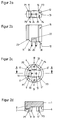
- Figure 2b shows a side view of the broad side 15 of the base 13, the bevel 11 of the underside 12 with the adjoining blocking surface 23 for standard bases can be seen, while from the recessed area 30 provided for use in the recess 6 of the socket Protrude from the underside of the contact pins 24, 25; According to FIG. 2b, it is also possible to create an additional encryption option for different types of radiators by means of different diameters of the pins 24, 25.
- the socket 1 can be seen in a plan view, the locking areas 4 of which are each provided with projections 5 'and 5' ', the plan view also showing the contact openings 9, 10 with electrical spring contacts 26, 27 for receiving the electrical contact pins 24, 25 of the base are recognizable. Furthermore, the bevel flank 8 can be seen between the surface 7 of the base 2 and the depression 6 provided with the contact openings 9, 10. On the opposite sides 18, 19 the rigidly connected to the base 2 - but here shown without the retaining springs - fastening tabs 20 can be seen, the associated retaining springs holding the base 13 after the insertion of the base 13 with the locking lugs 22 within the socket 1.
- FIG. 2d shows a cross section through the holder 1, along the section AA of FIG. 2c, the recessed area 6, with the contact openings, the ramp 8 and the surface 7 of the base 2 of the holder being recognizable; the positions of the nose-like projections 5 ', 5' 'seen along the section AA are designated P1, P2.
- FIG. 3a shows the base 13 used in socket 1, the bevel 11 coming to rest on the ramp 8 of the socket, while the respective projections 5 ′, 5 ′′ protrude into the groove-shaped recesses 16 of the socket. Furthermore, the sectional view shows the contact pins 24, 25, which are introduced into the contact openings 9, 10 of the socket 1.
- FIG. 3b shows the base 13 located in the socket from its narrow side 29, it being possible to see how the base 20 is attached in the area of the fastening tabs Retaining springs 21 block the retaining lugs 22 of the base in such a way that base 13 is held in the stop of the socket 1 by means of spring force.
- Figure 3c shows a top view of the socket 13 inserted in the socket 1, the groove-shaped recesses 16 and the corresponding projections 5 'in the positions P1 and P2 being slightly displaced relative to one another along the axis of symmetry 3, so that here an expansion of the encryption possibility for different ones Is used.
- An important advantage of the invention is that the system of the nose-like projections 5 ', 5' 'offers a multitude of coding possibilities for different types of radiators, whereby one of the projections 5', 5 '' can also be omitted, for example, so that only a radiation source adapted to the socket can be accommodated with its base.
Landscapes
- Engineering & Computer Science (AREA)
- General Engineering & Computer Science (AREA)
- Fastening Of Light Sources Or Lamp Holders (AREA)
Applications Claiming Priority (2)
| Application Number | Priority Date | Filing Date | Title |
|---|---|---|---|
| DE19531713 | 1995-08-31 | ||
| DE19531713A DE19531713C2 (de) | 1995-08-31 | 1995-08-31 | Fassung zur Aufnahme einer Strahlenquelle sowie Strahlenquelle mit Sockel |
Publications (3)
| Publication Number | Publication Date |
|---|---|
| EP0762562A2 true EP0762562A2 (fr) | 1997-03-12 |
| EP0762562A3 EP0762562A3 (fr) | 1997-07-09 |
| EP0762562B1 EP0762562B1 (fr) | 2000-05-03 |
Family
ID=7770646
Family Applications (1)
| Application Number | Title | Priority Date | Filing Date |
|---|---|---|---|
| EP96111241A Expired - Lifetime EP0762562B1 (fr) | 1995-08-31 | 1996-07-12 | Douille pour le support d'une source de rayons et source de rayons ayant un socle |
Country Status (3)
| Country | Link |
|---|---|
| US (1) | US5795192A (fr) |
| EP (1) | EP0762562B1 (fr) |
| DE (2) | DE19531713C2 (fr) |
Cited By (1)
| Publication number | Priority date | Publication date | Assignee | Title |
|---|---|---|---|---|
| WO2010102698A1 (fr) | 2009-03-09 | 2010-09-16 | Heraeus Noblelight Gmbh | Source de rayonnement, notamment lampe halogène avec corps de lampe et son module de retenue |
Families Citing this family (12)
| Publication number | Priority date | Publication date | Assignee | Title |
|---|---|---|---|---|
| DE19706905B4 (de) * | 1997-02-20 | 2004-09-02 | Holzer, Walter, Prof. Dr.h.c. Ing. | Berührungssicheres Sockel-/Fassungssystem für Glüh- und Gasentladungslampen |
| ITBS20030061A1 (it) * | 2003-06-24 | 2004-12-25 | E M C Colosio S R L | Portalampada e metodo di realizzazione dello stesso. |
| US7033065B2 (en) * | 2003-08-06 | 2006-04-25 | The Coleman Company, Inc. | Lamp retainer assembly |
| WO2007098163A2 (fr) * | 2006-02-27 | 2007-08-30 | Lightsources, Inc. | lampe ultraviolette a utiliser dans un epurateur d'eau |
| DE102008008809B3 (de) * | 2008-02-12 | 2009-04-30 | Bjb Gmbh & Co.Kg | Vorrichtung zur Anordnung einer Lampe, insbesondere einer Kompaktleuchtstofflampe |
| CN101788133B (zh) * | 2010-03-18 | 2012-11-28 | 海洋王照明科技股份有限公司 | 灯泡夹持组件 |
| CN105757616B (zh) * | 2014-12-16 | 2019-12-03 | 海洋王照明科技股份有限公司 | 灯具及其减振垫 |
| USD756928S1 (en) | 2015-05-19 | 2016-05-24 | Lightsources Inc. | Base for high pressure lamp |
| USD757653S1 (en) | 2015-05-19 | 2016-05-31 | Lightsources Inc. | Base for high pressure lamp |
| USD768081S1 (en) | 2015-05-19 | 2016-10-04 | Lightsources Inc. | Base for high pressure lamp |
| USD757654S1 (en) | 2015-05-19 | 2016-05-31 | Lightsources Inc. | Base for high pressure lamp |
| USD767493S1 (en) | 2015-05-19 | 2016-09-27 | Lightsources Inc. | Base for high pressure lamp |
Family Cites Families (8)
| Publication number | Priority date | Publication date | Assignee | Title |
|---|---|---|---|---|
| GB345492A (en) * | 1930-03-21 | 1931-03-26 | Belling & Lee Ltd | Improvements in or relating to plug and socket devices for connecting mains-operated wireless sets and the like to mains |
| DE8231975U1 (de) * | 1982-11-13 | 1983-04-07 | Rensch, Jürgen, 5650 Solingen | Stöckel für eine Kompakt-Leuchtstofflampe |
| DE8520290U1 (de) * | 1985-07-13 | 1985-09-19 | Theimer, Siegfried, 6484 Birstein | Brenner |
| US4713019A (en) * | 1986-09-17 | 1987-12-15 | Edwin Gaynor | Sockets for compact fluorescent lamps |
| US5035643A (en) * | 1989-05-17 | 1991-07-30 | Zanxx, Inc. | Axial low profile lamp socket assembly |
| US5207600A (en) * | 1990-09-28 | 1993-05-04 | U.S. Philips Corporation | Lampholder for a high-pressure gas discharge lamp |
| EP0708995A4 (fr) * | 1993-07-13 | 1997-03-19 | Chrysler Corp | Ensemble connecteur pour lampes |
| DE9314625U1 (de) * | 1993-09-28 | 1993-12-02 | DUAL-ZENTRUM GmbH Industrielle Innovation und Kreativtechnologien durch Computerlösungen, 01219 Dresden | Codierbare Steckverbindung |
-
1995
- 1995-08-31 DE DE19531713A patent/DE19531713C2/de not_active Expired - Fee Related
-
1996
- 1996-07-12 EP EP96111241A patent/EP0762562B1/fr not_active Expired - Lifetime
- 1996-07-12 DE DE59605111T patent/DE59605111D1/de not_active Expired - Lifetime
- 1996-08-05 US US08/692,328 patent/US5795192A/en not_active Expired - Lifetime
Cited By (2)
| Publication number | Priority date | Publication date | Assignee | Title |
|---|---|---|---|---|
| WO2010102698A1 (fr) | 2009-03-09 | 2010-09-16 | Heraeus Noblelight Gmbh | Source de rayonnement, notamment lampe halogène avec corps de lampe et son module de retenue |
| DE102009011765A1 (de) | 2009-03-09 | 2010-10-07 | Heraeus Noblelight Gmbh | Strahlenquelle, insbesondere Halogenlampe mit Lampenkörper und Baugruppe für dessen Halterung |
Also Published As
| Publication number | Publication date |
|---|---|
| DE19531713C2 (de) | 2000-07-13 |
| EP0762562A3 (fr) | 1997-07-09 |
| DE19531713A1 (de) | 1997-03-06 |
| US5795192A (en) | 1998-08-18 |
| DE59605111D1 (de) | 2000-06-08 |
| EP0762562B1 (fr) | 2000-05-03 |
Similar Documents
| Publication | Publication Date | Title |
|---|---|---|
| EP0283087B1 (fr) | Armature pour lampe fluorescente allongée | |
| EP0762562A2 (fr) | Douille pour le support d'une source de rayons et source de rayons ayant un socle | |
| DE10227016B4 (de) | Elektrischer Steckverbinder | |
| DE102007043266A1 (de) | Leuchtstofflampenfassung mit erhöhter Kontaktsicherheit | |
| EP0860654B1 (fr) | Armature allongée pour bandes lumineuses | |
| DE19506365C2 (de) | Verbinderbefestigungsanordnung | |
| DE2933359A1 (de) | Elektrische lampe mit einem huelsenfoermigen sockel | |
| EP3114400A1 (fr) | Luminaire ou ensemble lumineux comprenant un élément support allongé et un module lumineux fixé de manière libérable | |
| DE2013542A1 (fr) | ||
| DE19755513A1 (de) | Dehnverbinder für aufeinanderfolgende Stromschienen einer Schleifleitung | |
| DE20116523U1 (de) | Lampenfassung sowie Baugruppe bestehend aus Lampenfassung und Reflektor | |
| DE60002670T2 (de) | Lampenadapter mit integriertem elektronischen vorschaltgerät zur aufnahme von hochleistunsleuchtstofflampen, zum ersetzen von leuchtstofflampen mit einem induktiven vorschaltgerät | |
| WO2011051127A1 (fr) | Dispositif d'éclairage routier et procédé de montage | |
| DE29522129U1 (de) | Fassung zur Aufnahme einer Strahlenquelle sowie Strahlenquelle mit Sockel | |
| DE202018106703U1 (de) | Wand- oder Deckenleuchte | |
| AT14927U1 (de) | Beleuchtungsvorrichtung und Befestigungsanordnung für die Beleuchtungsvorrichtung | |
| DE60037175T2 (de) | Niederdruck gasentladungslampe | |
| DE19913552B4 (de) | Rotationsmäßig betätigbares elektrisches Bauteil mit einem durch einen Gewindeantrieb betätigten Gleitstück | |
| EP1074788B1 (fr) | Elément de fixation pour composants utilisés dans la technique d'éclairage dans un luminaire | |
| EP1329931B1 (fr) | Lampe compacte à décharge à basse pression | |
| EP1443266B1 (fr) | Dispositif de fixation pour deux supports de lampe | |
| EP1099903B1 (fr) | Luminaire | |
| DE69401973T2 (de) | Leuchte | |
| WO1990014703A1 (fr) | Lampe a reflecteur a lumiere froide | |
| DE69837191T2 (de) | Leuchte |
Legal Events
| Date | Code | Title | Description |
|---|---|---|---|
| PUAI | Public reference made under article 153(3) epc to a published international application that has entered the european phase |
Free format text: ORIGINAL CODE: 0009012 |
|
| 17P | Request for examination filed |
Effective date: 19960730 |
|
| AK | Designated contracting states |
Kind code of ref document: A2 Designated state(s): DE GB IT NL |
|
| PUAL | Search report despatched |
Free format text: ORIGINAL CODE: 0009013 |
|
| AK | Designated contracting states |
Kind code of ref document: A3 Designated state(s): DE GB IT NL |
|
| 17Q | First examination report despatched |
Effective date: 19980901 |
|
| GRAG | Despatch of communication of intention to grant |
Free format text: ORIGINAL CODE: EPIDOS AGRA |
|
| GRAG | Despatch of communication of intention to grant |
Free format text: ORIGINAL CODE: EPIDOS AGRA |
|
| GRAH | Despatch of communication of intention to grant a patent |
Free format text: ORIGINAL CODE: EPIDOS IGRA |
|
| GRAH | Despatch of communication of intention to grant a patent |
Free format text: ORIGINAL CODE: EPIDOS IGRA |
|
| GRAA | (expected) grant |
Free format text: ORIGINAL CODE: 0009210 |
|
| AK | Designated contracting states |
Kind code of ref document: B1 Designated state(s): DE GB IT NL |
|
| GBT | Gb: translation of ep patent filed (gb section 77(6)(a)/1977) |
Effective date: 20000504 |
|
| REF | Corresponds to: |
Ref document number: 59605111 Country of ref document: DE Date of ref document: 20000608 |
|
| ITF | It: translation for a ep patent filed | ||
| EN | Fr: translation not filed | ||
| PLBE | No opposition filed within time limit |
Free format text: ORIGINAL CODE: 0009261 |
|
| STAA | Information on the status of an ep patent application or granted ep patent |
Free format text: STATUS: NO OPPOSITION FILED WITHIN TIME LIMIT |
|
| 26N | No opposition filed | ||
| REG | Reference to a national code |
Ref country code: GB Ref legal event code: IF02 |
|
| PGFP | Annual fee paid to national office [announced via postgrant information from national office to epo] |
Ref country code: NL Payment date: 20150721 Year of fee payment: 20 |
|
| PGFP | Annual fee paid to national office [announced via postgrant information from national office to epo] |
Ref country code: DE Payment date: 20150721 Year of fee payment: 20 Ref country code: GB Payment date: 20150721 Year of fee payment: 20 |
|
| PGFP | Annual fee paid to national office [announced via postgrant information from national office to epo] |
Ref country code: IT Payment date: 20150727 Year of fee payment: 20 |
|
| REG | Reference to a national code |
Ref country code: DE Ref legal event code: R071 Ref document number: 59605111 Country of ref document: DE |
|
| REG | Reference to a national code |
Ref country code: NL Ref legal event code: MK Effective date: 20160711 |
|
| REG | Reference to a national code |
Ref country code: GB Ref legal event code: PE20 Expiry date: 20160711 |
|
| PG25 | Lapsed in a contracting state [announced via postgrant information from national office to epo] |
Ref country code: GB Free format text: LAPSE BECAUSE OF EXPIRATION OF PROTECTION Effective date: 20160711 |