EP1443266B1 - Dispositif de fixation pour deux supports de lampe - Google Patents
Dispositif de fixation pour deux supports de lampe Download PDFInfo
- Publication number
- EP1443266B1 EP1443266B1 EP03026739A EP03026739A EP1443266B1 EP 1443266 B1 EP1443266 B1 EP 1443266B1 EP 03026739 A EP03026739 A EP 03026739A EP 03026739 A EP03026739 A EP 03026739A EP 1443266 B1 EP1443266 B1 EP 1443266B1
- Authority
- EP
- European Patent Office
- Prior art keywords
- holding device
- carrier arms
- base body
- fittings
- carrier
- Prior art date
- Legal status (The legal status is an assumption and is not a legal conclusion. Google has not performed a legal analysis and makes no representation as to the accuracy of the status listed.)
- Expired - Lifetime
Links
- 230000007704 transition Effects 0.000 claims 1
- 238000005192 partition Methods 0.000 description 3
- 238000013461 design Methods 0.000 description 2
- 238000010438 heat treatment Methods 0.000 description 2
- 238000012546 transfer Methods 0.000 description 2
- 238000013459 approach Methods 0.000 description 1
- 238000010276 construction Methods 0.000 description 1
- 230000007423 decrease Effects 0.000 description 1
- 230000001419 dependent effect Effects 0.000 description 1
- 238000011161 development Methods 0.000 description 1
- 230000018109 developmental process Effects 0.000 description 1
- 238000001746 injection moulding Methods 0.000 description 1
- 238000003780 insertion Methods 0.000 description 1
- 230000037431 insertion Effects 0.000 description 1
- 230000003993 interaction Effects 0.000 description 1
- 238000013519 translation Methods 0.000 description 1
Images


Classifications
-
- F—MECHANICAL ENGINEERING; LIGHTING; HEATING; WEAPONS; BLASTING
- F21—LIGHTING
- F21V—FUNCTIONAL FEATURES OR DETAILS OF LIGHTING DEVICES OR SYSTEMS THEREOF; STRUCTURAL COMBINATIONS OF LIGHTING DEVICES WITH OTHER ARTICLES, NOT OTHERWISE PROVIDED FOR
- F21V19/00—Fastening of light sources or lamp holders
- F21V19/02—Fastening of light sources or lamp holders with provision for adjustment, e.g. for focusing
-
- F—MECHANICAL ENGINEERING; LIGHTING; HEATING; WEAPONS; BLASTING
- F21—LIGHTING
- F21V—FUNCTIONAL FEATURES OR DETAILS OF LIGHTING DEVICES OR SYSTEMS THEREOF; STRUCTURAL COMBINATIONS OF LIGHTING DEVICES WITH OTHER ARTICLES, NOT OTHERWISE PROVIDED FOR
- F21V19/00—Fastening of light sources or lamp holders
- F21V19/0075—Fastening of light sources or lamp holders of tubular light sources, e.g. ring-shaped fluorescent light sources
- F21V19/008—Fastening of light sources or lamp holders of tubular light sources, e.g. ring-shaped fluorescent light sources of straight tubular light sources, e.g. straight fluorescent tubes, soffit lamps
-
- H—ELECTRICITY
- H01—ELECTRIC ELEMENTS
- H01R—ELECTRICALLY-CONDUCTIVE CONNECTIONS; STRUCTURAL ASSOCIATIONS OF A PLURALITY OF MUTUALLY-INSULATED ELECTRICAL CONNECTING ELEMENTS; COUPLING DEVICES; CURRENT COLLECTORS
- H01R33/00—Coupling devices specially adapted for supporting apparatus and having one part acting as a holder providing support and electrical connection via a counterpart which is structurally associated with the apparatus, e.g. lamp holders; Separate parts thereof
- H01R33/05—Two-pole devices
- H01R33/06—Two-pole devices with two current-carrying pins, blades or analogous contacts, having their axes parallel to each other
- H01R33/08—Two-pole devices with two current-carrying pins, blades or analogous contacts, having their axes parallel to each other for supporting tubular fluorescent lamp
- H01R33/0818—Two-pole devices with two current-carrying pins, blades or analogous contacts, having their axes parallel to each other for supporting tubular fluorescent lamp for a plurality of lamps
Definitions
- the present invention relates to a holding device for the lamp holders of a so-called two-lamp lamp according to the preamble of claim 1.
- Luminaires with elongated gas discharge lamps are known in a variety of forms.
- the holder and power supply of the gas discharge lamps takes place via arranged on the end faces of the lights versions, each in a holding device - the so-called. - Holder are arranged. It is also known to arrange two gas discharge lamps in parallel side by side in a lamp to increase the amount of light emitted by the lamp in total.
- the frame holders are usually designed such that the sockets for the gas discharge lamps and thus the gas discharge lamps themselves are very close together.
- This close-fitting arrangement is chosen because on the one hand in this way space is saved and on the other hand, the two gas discharge lamps appear as a nearly uniform light source.
- this close arrangement has the disadvantage that the two gas discharge lamps heat each other strongly, which is particularly associated with fluorescent tubes with the result that the efficiency of the lamps and thus the luminous efficacy decreases.
- socket holders for every two gas discharge lamp sockets in which the sockets and thus the two gas discharge lamps have a greater distance from each other.
- the greater distance would increase the efficiency of the gas discharge lamps as explained above.
- the currently used dual-lamp holder holders have a predominantly number of closely spaced versions, it would also be desirable to design the newly designed socket holder such that it can be placed in a state that corresponds to the previously used socket holders. This is desirable because the loading of the socket holder with the lamp holders and the subsequent attachment to the support elements of the lights automatically, ie with robots or trained accordingly Tools done. In order to use these expensive tools for the holder with the lamp sockets further apart, he would have to be able to be brought into a mounting position that corresponds to that of the previous frame holder.
- This patent describes a socket holder, which consists of a box-shaped body, can be attached to the support arms for holding a respective socket for a gas discharge lamp.
- the first state in which the support arms are close together could then be used as a mounting position, the support arms are transferred after the assembly with the lamp holders in a user position in which they have a further distance from each other.
- a holding device for two versions which has a base body and two support arms provided thereon, each for a socket.
- the support arms can be extended and retracted.
- the support arms each have a joint, so that the relative position of the two versions can be further varied by a corresponding pivoting movement.
- the present invention has for its object to provide a holding device for holding two sockets for gas discharge lamps, in which a larger change in the distance between the two lamp sockets is possible.
- the holding device consists of a base body and two arranged on the body support arms for holding a respective socket for a gas discharge lamp.
- the support arms are each optionally pivotable relative to the base body, wherein to achieve a greater distance according to the invention additionally their length is adjustable. The Adjusting the length can be effected in particular by the carrier arms making a translational movement relative to the base body.
- the translational movement implies that the two support arms each have longer dimensions than previously customary. Due to this greater length, it is possible to further increase the distance between the two versions to each other, as in the frame holder according to the GB 577,239 the case is. In particular, in the holding device according to the present invention, the aforementioned minimum required height for mounting reason easier adhered and still a greater distance between the two lamp sockets can be achieved.
- the holding device thus opens up the possibility of the support arms with the lamp holders from a first mounting position, which corresponds to the arrangement of previous frame holder and in which the support arms can be fitted with the versions, in a second user position in which the lamp sockets the desired large distance from each other have to transfer, wherein the support arms to achieve the user position from the mounting position relative to the base body perform both a translational movement and a pivoting movement.
- the existing tools for automatic mounting and loading the socket holder can also be used for the new holding device.
- the support arms are preferably slidably mounted relative to the base body and for this purpose each have an elongated guide groove into which a guide pin arranged on the base body engages. At the two ends of a guide groove can then be arranged in each case a detent opening, wherein the remote from the sockets lying latching openings in each case define the pivot axes for the two support arms.
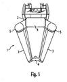
- Fig. 1 intended to illustrate the advantage of the holding device according to the invention. Shown is a two-lamp lamp 1, which initially has an elongated support member 2 for holding two fluorescent lamps 3. The holder of the fluorescent lamps 3 on the carrier element 2 by means of two holding devices 4, which are respectively arranged on the end sides of the support member 2. Each holding device 4 is used for storage of two lamp holders 5, in which the fluorescent lamps 3 are used with their front ends.
- the lamp holders 5 and thus the fluorescent lamps 3 a relatively large distance from each other. Due to this large distance, mutual heating of the fluorescent lamps 3, which would lead to a drop in lamp efficiency, is largely excluded. Although the fluorescent lamps 3 thereby occupy a slightly larger space and now no longer appear as a single light source, this is offset by the advantage of greater lamp efficiency.
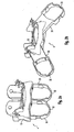
- the Fig. 2a and 2b show the holding device 4 according to the invention in two different positions, Fig. 2a in the mounting position and Fig. 2b in the Fig. 1 corresponding user position.
- the holding device 4 consists essentially of a base body 10 to which two support arms 30 are fixed, each having a cup-shaped recess 32 for receiving a (not shown here) lamp socket. Both the base body 10 and the support arms 30 are preferably made of plastic and can be produced in particular by injection molding.
- the two support arms 30 can perform relative to the main body 10 a translational movement and a pivoting movement to between the both in the Fig. 2a and 2b change positions shown. They are in the in Fig. 2a shown mounting position arranged such that the arrangement of the recesses 32 corresponds to the previously used holder holders for two-lamp lights. This mounting position is used to insert the sockets for the gas discharge lamps in the recesses 32, to attach the holding device 4 to the support element of the lamp and to connect the lampholders to the power supply lines. All these steps are carried out automatically with robots or appropriately designed tools, wherein the aids used for the previous frame holder can be used as desired for the holding device 4 according to the invention.
- the holding device 4 in the in Fig. 2b shown user position to be transferred, which takes place in that the two support arms 30 relative to the base body 10 first perform a translational movement down and then an outwardly directed pivoting movement.
- the downward translational movement initially causes an extension of the support arms 30 and thus an increase in the distance of the lamp sockets or the associated gas discharge lamps relative to the mounting reason. Although this is subsequently at least partially canceled by the lateral pivoting movement, as a result of the translational movement, however, the support arms 30 can be pivoted further outwards than was previously possible.
- the holding device 4 makes it possible to set a relatively large distance in the user position.
- the Fig. 3-6 first show the structure of the main body 10, Fig. 3 in a view from below and the Fig. 4-6 in different perspective views.
- the base body 10 initially consists of a box-shaped holding portion 11 for the support arms 30, from the front of which an assembly tongue 12 extends.
- the mounting tongue 12 serves to fasten the main body 10 to the carrier element of the luminaire and accordingly has structured wall sections. Further, two locking projections 13 are provided in the side regions of the mounting tongue 12, which cooperate with corresponding recesses on the support element of the lamp and cause a latching. As a result, an unintentional sliding of the holding device is avoided by the support member.
- the holding region 11 of the main body 10 is divided by a centrally arranged partition wall 14 into two receiving regions 15, which each serve to receive one of the two carrier arms.
- the two receiving areas 15 are each enclosed by four side walls 14, 16, 18 and 22, wherein the partition wall 14 opposite end walls 16 each have an upwardly drawn recess 17.
- the recesses 17 allow the lateral pivoting of the support arms 30, as will be explained in detail later.
- each have a circular detent opening 19 is arranged, which is continued by a recess 20 extending in the side wall 18 to the top of the side wall 18.
- latching projections 21 which protrude into the interior of the receiving areas 15 and allow locking of the laterally swung-out support arms 30 in the user position.
- a carrier arm 30 consists of an elongate arm 31, at one end of a pot-shaped recess 32 is arranged for receiving a lamp holder.
- the recess 32 has in the present case, the contour of a conventional fluorescent lamp socket, wherein in the side walls openings 33 and 34 are arranged, which facilitate insertion of the socket or a later removal from the recess 32.
- the front side 35 of the arm 31 has a circular latching projection 36 and two parallelogram-shaped latching recesses 37.
- the latching recesses 37 are arranged on both sides of the central axis of the support arm 30 mirror images of each other, which has the advantage that the thus symmetrically formed support arm 30 can be arranged on both the left and on the right side of the body 10. Accordingly, only one type of support arms 30 has to be provided, as a result of which the outlay on assembly of the holding device is considerably reduced.
- the first detent opening 39a being at the level of the detent projection 36 of the front side 35 and the second detent opening 39b approximately at the level of the two detent recesses 37.
- Both latching openings 39a and 39b are connected to one another via a guide groove 40 extending on the outside of the rear wall 38.
- two locking slots 41 are also arranged, wherein the two-sided arrangement again takes place on the basis of the previously described desired symmetry of the support arm 30.
- Fig. 11 are located on the insides of the two narrow walls 42 of the arm 31 through openings 43 which extend from the upper end face of the arm 31 to the recess 32 for the lamp holder and ultimately open into this. These passage openings 43 are used to guide wires to connect the lamp sockets with the power supply lines of the lamp.
- the two support arms 30 are in a close-spaced position, wherein they are arranged vertically.
- the guide pins 23 of the main body 10 respectively engage in the lower detent openings 39b on the rear walls 38 of the support arms 30.
- a slight locking of the support arms 30 is ensured with the main body 10.
- the side walls of the recesses 32 of the support arms 30 abut against the partition wall 14 and at the lower edges of the latching projections 21 and 24 of the base body 10, is also a lateral fixation of the support arms 30th guaranteed.
- the guide pins 23 and / or latching projections 36 thus engage in the corresponding recesses 19 and 39a, thereby ensuring secure holding of the carrier arm 30 on the base body 10.
- the projections 23 and 36 or recesses 19 and 39a further define two pivot axes about which now the two support arms 30 can be pivoted laterally outwards, in which case they each pivot into the recesses 17 of the side walls 16 of the base body 10.
- the support arms 30 are in each case pivoted so far outward until they come with their side walls 42 in abutment with the upper edges of the recesses 17. These are dimensioned such that in this position, furthermore, the latching projections 21 and 24 of the base body 10 in the recesses 37 and 41 of the support arm 30 oriented toward the center of the main body 10, respectively. This engagement causes a firm locking of the support arms 30 in the in Fig. 2b shown user position, by the unintentional pivoting of the support arms 30 is excluded.
- the holding device 4 according to the invention can thus be transferred by simple and few handles from the mounting position to the user position. Since the locking of the two support arms 30 in the various positions as well as the guide during the translation and pivoting movement takes place exclusively by the arranged on the base body 10 and the support arms 30 locking and guide elements, no additional components are required to the desired functions achieve.
- the present holding device is thus characterized in particular by its simple and inexpensive construction. At the same time it offers the possibility of arranging the lamp sockets and thus the gas discharge lamps after an automatically performed assembly at a very large distance from each other and thus to increase the lamp efficiency.
Landscapes
- Engineering & Computer Science (AREA)
- General Engineering & Computer Science (AREA)
- Fastening Of Light Sources Or Lamp Holders (AREA)
- Control And Other Processes For Unpacking Of Materials (AREA)
- Vessels And Coating Films For Discharge Lamps (AREA)
- Non-Portable Lighting Devices Or Systems Thereof (AREA)
- Wrapping Of Specific Fragile Articles (AREA)
- Vehicle Body Suspensions (AREA)
Claims (16)
- Dispositif de fixation (4) pour deux supports (5) de deux lampes à décharge (3) oblongues juxtaposées dans un éclairage (1), constitué d'un corps de base (10) et de deux bras porteurs (30) prévus sur le corps de base (10) pour un support (5) chacun,
caractérisé en ce que les bras porteurs (30) peuvent pivoter par rapport au corps de base (10) de telle manière que les supports (5) situés sur les bras porteurs (30) présentent une distance pouvant être choisie,
dans lequel, en plus, la longueur des bras porteurs (30) peut être modifiée au choix, et la longueur des bras porteurs (30) peut être agrandie par un mouvement de translation s'effectuant dans une direction par rapport au corps de base (10). - Dispositif de fixation selon la revendication 1, caractérisé en ce que les bras porteurs (30) peuvent effectuer un mouvement de translation par rapport au corps de base (10) pour modifier leur longueur.
- Dispositif de fixation selon la revendication 2, caractérisé en ce que les bras porteurs (30) sont montés coulissants par rapport au corps de base (10).
- Dispositif de maintien selon la revendication 3, caractérisé en ce que les bras supports (30) présentent chacun une rainure de guidage oblongue (40) dans laquelle s'engage un ergot de guidage (23) placé sur le corps de base (10).
- Dispositif de fixation selon la revendication 4, caractérisé en ce qu'aux deux extrémités d'une rainure de guidage (40) est placée à chaque fois une ouverture de crantage (39a, 39b) coopérant avec l'ergot de guidage (23).
- Dispositif de fixation selon la revendication 5, caractérisé en ce que les ouvertures de crantage (39a) distantes des supports (5) définissent les axes de pivotement pour les bras porteurs (30).
- Dispositif de fixation selon l'une des revendications 2 à 6, caractérisé en ce que les deux bras porteurs (30) peuvent être déplacés entre une première position et une deuxième position, les supports (5) situés sur les bras porteurs (30) présentant entre eux une plus faible distance dans la première position que dans la deuxième position,
et en ce que, pour atteindre la deuxième position, les bras porteurs (30) effectuent un mouvement de translation ainsi qu'un mouvement de pivotement par rapport au corps de base (10). - Dispositif de fixation selon la revendication 7, caractérisé en ce que la première position est une position de montage dans laquelle les bras porteurs (30) sont équipés des supports (5), et en ce que la deuxième position est une position d'utilisation dans laquelle les bras porteurs (30) se trouvent pendant le fonctionnement de l'éclairage.
- Dispositif de fixation selon la revendication 7 ou 8, caractérisé en ce que, lors du passage de la première position à la deuxième position, les deux bras porteurs (30) effectuent d'abord le mouvement de translation, puis le mouvement de pivotement.
- Dispositif de fixation selon l'une des revendications 7 à 9, caractérisé en ce que les deux bras porteurs (30) peuvent être immobilisés par rapport au corps de base (10) tant dans la première position que dans la deuxième position.
- Dispositif de fixation selon la revendication 10, caractérisé en ce que le corps de base (10) et les bras porteurs (30) présentent des éléments de crantage et de guidage coopérants (19, 20, 21, 23, 24, 36, 37, 39a, 39b, 40, 41) les uns avec les autres.
- Dispositif de fixation selon la revendication 11, caractérisé en ce que les éléments de crantage et de guidage (36, 37, 39a, 39b, 40, 41) situés sur les bras porteurs (30) sont disposés symétriquement par rapport à l'axe médian du bras porteur (30) concerné.
- Dispositif de fixation selon l'une des revendications précédentes, caractérisé en ce que les bras porteurs (30) présentent à chaque fois, à leurs extrémités opposées au corps de base (10), un évidement (32) destiné à recevoir un support (5).
- Dispositif de maintien selon la revendication 13, caractérisé en ce que l'évidement (32) présente un contour correspondant à un support de tubes fluorescents.
- Dispositif de fixation selon la revendication 13 ou 14, caractérisé en ce que les bras porteurs (30) présentent des passages (43) pour faire passer des lignes électriques, qui s'étendent depuis la face frontale supérieure d'un bras porteur (31) jusqu'à l'évidement (32) destiné au support.
- Éclairage (1) à deux sources comprenant deux lampes à décharge (3) oblongues juxtaposées, qui sont tenues chacune par deux supports (5) et sont alimentées en électricité,
caractérisé par deux dispositifs de fixation (4) placés sur les faces frontales de l'éclairage (1) pour les supports (5), selon l'une des revendications précédentes.
Applications Claiming Priority (2)
| Application Number | Priority Date | Filing Date | Title |
|---|---|---|---|
| DE10303934A DE10303934A1 (de) | 2003-01-31 | 2003-01-31 | Haltevorrichtung für zwei Lampenfassungen |
| DE10303934 | 2003-01-31 |
Publications (2)
| Publication Number | Publication Date |
|---|---|
| EP1443266A1 EP1443266A1 (fr) | 2004-08-04 |
| EP1443266B1 true EP1443266B1 (fr) | 2008-06-18 |
Family
ID=32603071
Family Applications (1)
| Application Number | Title | Priority Date | Filing Date |
|---|---|---|---|
| EP03026739A Expired - Lifetime EP1443266B1 (fr) | 2003-01-31 | 2003-11-21 | Dispositif de fixation pour deux supports de lampe |
Country Status (4)
| Country | Link |
|---|---|
| EP (1) | EP1443266B1 (fr) |
| AT (1) | ATE398753T1 (fr) |
| DE (2) | DE10303934A1 (fr) |
| NO (1) | NO20040430L (fr) |
Families Citing this family (1)
| Publication number | Priority date | Publication date | Assignee | Title |
|---|---|---|---|---|
| US20120134146A1 (en) * | 2009-06-10 | 2012-05-31 | Andrew Smith | Lighting apparatus |
Family Cites Families (6)
| Publication number | Priority date | Publication date | Assignee | Title |
|---|---|---|---|---|
| GB577239A (en) | 1941-06-03 | 1946-05-10 | Gen Electric Co Ltd | Improvements in supports for electric discharge lamps |
| US4238815A (en) * | 1978-06-29 | 1980-12-09 | Edison Price, Incorporated | Recessed light fixture |
| DE8711056U1 (de) * | 1987-08-13 | 1987-10-01 | Siemens AG, 1000 Berlin und 8000 München | Langfeldleuchte |
| JPH03184205A (ja) * | 1989-12-12 | 1991-08-12 | Tokyo Electric Co Ltd | 照明器具 |
| JPH06131908A (ja) * | 1992-10-14 | 1994-05-13 | Tokyo Electric Co Ltd | 照明器具 |
| US6102550A (en) * | 1999-02-16 | 2000-08-15 | Photronix, Llc | Bracket assembly for fluorescent lighting fixture having removable, high-frequency power output ballast |
-
2003
- 2003-01-31 DE DE10303934A patent/DE10303934A1/de not_active Withdrawn
- 2003-11-21 EP EP03026739A patent/EP1443266B1/fr not_active Expired - Lifetime
- 2003-11-21 AT AT03026739T patent/ATE398753T1/de not_active IP Right Cessation
- 2003-11-21 DE DE50310002T patent/DE50310002D1/de not_active Expired - Lifetime
-
2004
- 2004-01-30 NO NO20040430A patent/NO20040430L/no not_active Application Discontinuation
Also Published As
| Publication number | Publication date |
|---|---|
| DE50310002D1 (de) | 2008-07-31 |
| EP1443266A1 (fr) | 2004-08-04 |
| ATE398753T1 (de) | 2008-07-15 |
| NO20040430L (no) | 2004-08-02 |
| DE10303934A1 (de) | 2004-08-12 |
Similar Documents
| Publication | Publication Date | Title |
|---|---|---|
| WO2001091250A1 (fr) | Systeme a rail conducteur | |
| WO2001091249A1 (fr) | Systeme de barre omnibus | |
| EP0897511B1 (fr) | Lampe a champ d'eclairage lineaire susceptible de s'inserer dans un montage de bande lumineuse | |
| EP2314912A1 (fr) | Lampe à DEL dotée d'un angle de rayonnement réglable en continu | |
| AT15075U1 (de) | Leuchte zur Verwendung in einem Lichtbandsystem sowie Lichtbandsystem | |
| WO2001091248A1 (fr) | Systeme de rails conducteurs | |
| WO2001069129A1 (fr) | Lampe encastree pourvue d'une bague de retenue pour composants additionnels | |
| EP0762562B1 (fr) | Douille pour le support d'une source de rayons et source de rayons ayant un socle | |
| DE60226107T2 (de) | Elektrische Verbindungsanordnung für Lampe | |
| EP0012234B1 (fr) | Armature à lampe fluorescente | |
| EP1443266B1 (fr) | Dispositif de fixation pour deux supports de lampe | |
| EP3876364B1 (fr) | Système d'éclairage sur rail | |
| WO2001069128A1 (fr) | Lampe encastree avec reflecteur en forme de dome | |
| DE19955072B4 (de) | Adapter zur Umrüstung von Leuchten mit induktiven Vorschaltgeräten auf elektronischen Betrieb | |
| DE102018101503A1 (de) | Elektrische Steckverbindung zum Verbinden eines Leuchtmittels mit einer elektrischen Anschlussleitung | |
| EP3446031B1 (fr) | Appareil d'éclairage d'armoire de distribution pourvu d'une platine à source lumineuse réglable | |
| EP1074788B1 (fr) | Elément de fixation pour composants utilisés dans la technique d'éclairage dans un luminaire | |
| DE10100605A1 (de) | Elektrische Beleuchtungsvorrichtung mit einer punktförmigen Lichtquelle | |
| DE19954068B4 (de) | Leuchte | |
| DE230050C (fr) | ||
| EP1132681B1 (fr) | Système de rails de support | |
| DE19833217A1 (de) | Leuchtstoffröhrenleuchte | |
| DE10120741A1 (de) | Halterung für eine Lampe | |
| DE69837191T2 (de) | Leuchte | |
| EP0193014B1 (fr) | Lampe murale pour chambre de malade |
Legal Events
| Date | Code | Title | Description |
|---|---|---|---|
| PUAI | Public reference made under article 153(3) epc to a published international application that has entered the european phase |
Free format text: ORIGINAL CODE: 0009012 |
|
| AK | Designated contracting states |
Kind code of ref document: A1 Designated state(s): AT BE BG CH CY CZ DE DK EE ES FI FR GB GR HU IE IT LI LU MC NL PT RO SE SI SK TR |
|
| AX | Request for extension of the european patent |
Extension state: AL LT LV MK |
|
| 17P | Request for examination filed |
Effective date: 20041105 |
|
| AKX | Designation fees paid |
Designated state(s): AT BE BG CH CY CZ DE DK EE ES FI FR GB GR HU IE IT LI LU MC NL PT RO SE SI SK TR |
|
| 17Q | First examination report despatched |
Effective date: 20070110 |
|
| GRAC | Information related to communication of intention to grant a patent modified |
Free format text: ORIGINAL CODE: EPIDOSCIGR1 |
|
| GRAP | Despatch of communication of intention to grant a patent |
Free format text: ORIGINAL CODE: EPIDOSNIGR1 |
|
| RAP1 | Party data changed (applicant data changed or rights of an application transferred) |
Owner name: ZUMTOBEL LIGHTING GMBH |
|
| GRAS | Grant fee paid |
Free format text: ORIGINAL CODE: EPIDOSNIGR3 |
|
| GRAA | (expected) grant |
Free format text: ORIGINAL CODE: 0009210 |
|
| AK | Designated contracting states |
Kind code of ref document: B1 Designated state(s): AT BE BG CH CY CZ DE DK EE ES FI FR GB GR HU IE IT LI LU MC NL PT RO SE SI SK TR |
|
| REG | Reference to a national code |
Ref country code: GB Ref legal event code: FG4D Free format text: NOT ENGLISH |
|
| REF | Corresponds to: |
Ref document number: 50310002 Country of ref document: DE Date of ref document: 20080731 Kind code of ref document: P |
|
| REG | Reference to a national code |
Ref country code: CH Ref legal event code: EP |
|
| REG | Reference to a national code |
Ref country code: IE Ref legal event code: FG4D Free format text: LANGUAGE OF EP DOCUMENT: GERMAN |
|
| PG25 | Lapsed in a contracting state [announced via postgrant information from national office to epo] |
Ref country code: SI Free format text: LAPSE BECAUSE OF FAILURE TO SUBMIT A TRANSLATION OF THE DESCRIPTION OR TO PAY THE FEE WITHIN THE PRESCRIBED TIME-LIMIT Effective date: 20080618 Ref country code: FI Free format text: LAPSE BECAUSE OF FAILURE TO SUBMIT A TRANSLATION OF THE DESCRIPTION OR TO PAY THE FEE WITHIN THE PRESCRIBED TIME-LIMIT Effective date: 20080618 |
|
| PG25 | Lapsed in a contracting state [announced via postgrant information from national office to epo] |
Ref country code: NL Free format text: LAPSE BECAUSE OF FAILURE TO SUBMIT A TRANSLATION OF THE DESCRIPTION OR TO PAY THE FEE WITHIN THE PRESCRIBED TIME-LIMIT Effective date: 20080618 |
|
| NLV1 | Nl: lapsed or annulled due to failure to fulfill the requirements of art. 29p and 29m of the patents act | ||
| PG25 | Lapsed in a contracting state [announced via postgrant information from national office to epo] |
Ref country code: PT Free format text: LAPSE BECAUSE OF FAILURE TO SUBMIT A TRANSLATION OF THE DESCRIPTION OR TO PAY THE FEE WITHIN THE PRESCRIBED TIME-LIMIT Effective date: 20081118 Ref country code: ES Free format text: LAPSE BECAUSE OF FAILURE TO SUBMIT A TRANSLATION OF THE DESCRIPTION OR TO PAY THE FEE WITHIN THE PRESCRIBED TIME-LIMIT Effective date: 20080929 Ref country code: CZ Free format text: LAPSE BECAUSE OF FAILURE TO SUBMIT A TRANSLATION OF THE DESCRIPTION OR TO PAY THE FEE WITHIN THE PRESCRIBED TIME-LIMIT Effective date: 20080618 Ref country code: SE Free format text: LAPSE BECAUSE OF FAILURE TO SUBMIT A TRANSLATION OF THE DESCRIPTION OR TO PAY THE FEE WITHIN THE PRESCRIBED TIME-LIMIT Effective date: 20080918 |
|
| REG | Reference to a national code |
Ref country code: IE Ref legal event code: FD4D |
|
| PG25 | Lapsed in a contracting state [announced via postgrant information from national office to epo] |
Ref country code: RO Free format text: LAPSE BECAUSE OF FAILURE TO SUBMIT A TRANSLATION OF THE DESCRIPTION OR TO PAY THE FEE WITHIN THE PRESCRIBED TIME-LIMIT Effective date: 20080618 Ref country code: SK Free format text: LAPSE BECAUSE OF FAILURE TO SUBMIT A TRANSLATION OF THE DESCRIPTION OR TO PAY THE FEE WITHIN THE PRESCRIBED TIME-LIMIT Effective date: 20080618 |
|
| PLBE | No opposition filed within time limit |
Free format text: ORIGINAL CODE: 0009261 |
|
| STAA | Information on the status of an ep patent application or granted ep patent |
Free format text: STATUS: NO OPPOSITION FILED WITHIN TIME LIMIT |
|
| PG25 | Lapsed in a contracting state [announced via postgrant information from national office to epo] |
Ref country code: BG Free format text: LAPSE BECAUSE OF FAILURE TO SUBMIT A TRANSLATION OF THE DESCRIPTION OR TO PAY THE FEE WITHIN THE PRESCRIBED TIME-LIMIT Effective date: 20080918 Ref country code: DK Free format text: LAPSE BECAUSE OF FAILURE TO SUBMIT A TRANSLATION OF THE DESCRIPTION OR TO PAY THE FEE WITHIN THE PRESCRIBED TIME-LIMIT Effective date: 20080618 Ref country code: IE Free format text: LAPSE BECAUSE OF FAILURE TO SUBMIT A TRANSLATION OF THE DESCRIPTION OR TO PAY THE FEE WITHIN THE PRESCRIBED TIME-LIMIT Effective date: 20080618 Ref country code: EE Free format text: LAPSE BECAUSE OF FAILURE TO SUBMIT A TRANSLATION OF THE DESCRIPTION OR TO PAY THE FEE WITHIN THE PRESCRIBED TIME-LIMIT Effective date: 20080618 |
|
| 26N | No opposition filed |
Effective date: 20090319 |
|
| BERE | Be: lapsed |
Owner name: ZUMTOBEL LIGHTING GMBH Effective date: 20081130 |
|
| PG25 | Lapsed in a contracting state [announced via postgrant information from national office to epo] |
Ref country code: MC Free format text: LAPSE BECAUSE OF NON-PAYMENT OF DUE FEES Effective date: 20081130 |
|
| REG | Reference to a national code |
Ref country code: CH Ref legal event code: PL |
|
| GBPC | Gb: european patent ceased through non-payment of renewal fee |
Effective date: 20081121 |
|
| REG | Reference to a national code |
Ref country code: FR Ref legal event code: ST Effective date: 20090731 |
|
| PG25 | Lapsed in a contracting state [announced via postgrant information from national office to epo] |
Ref country code: BE Free format text: LAPSE BECAUSE OF NON-PAYMENT OF DUE FEES Effective date: 20081130 |
|
| PG25 | Lapsed in a contracting state [announced via postgrant information from national office to epo] |
Ref country code: CH Free format text: LAPSE BECAUSE OF NON-PAYMENT OF DUE FEES Effective date: 20081130 Ref country code: LI Free format text: LAPSE BECAUSE OF NON-PAYMENT OF DUE FEES Effective date: 20081130 |
|
| PG25 | Lapsed in a contracting state [announced via postgrant information from national office to epo] |
Ref country code: GB Free format text: LAPSE BECAUSE OF NON-PAYMENT OF DUE FEES Effective date: 20081121 |
|
| PG25 | Lapsed in a contracting state [announced via postgrant information from national office to epo] |
Ref country code: AT Free format text: LAPSE BECAUSE OF NON-PAYMENT OF DUE FEES Effective date: 20081121 |
|
| PG25 | Lapsed in a contracting state [announced via postgrant information from national office to epo] |
Ref country code: HU Free format text: LAPSE BECAUSE OF FAILURE TO SUBMIT A TRANSLATION OF THE DESCRIPTION OR TO PAY THE FEE WITHIN THE PRESCRIBED TIME-LIMIT Effective date: 20081219 Ref country code: CY Free format text: LAPSE BECAUSE OF FAILURE TO SUBMIT A TRANSLATION OF THE DESCRIPTION OR TO PAY THE FEE WITHIN THE PRESCRIBED TIME-LIMIT Effective date: 20080618 Ref country code: LU Free format text: LAPSE BECAUSE OF NON-PAYMENT OF DUE FEES Effective date: 20081121 |
|
| PG25 | Lapsed in a contracting state [announced via postgrant information from national office to epo] |
Ref country code: TR Free format text: LAPSE BECAUSE OF FAILURE TO SUBMIT A TRANSLATION OF THE DESCRIPTION OR TO PAY THE FEE WITHIN THE PRESCRIBED TIME-LIMIT Effective date: 20080618 |
|
| PG25 | Lapsed in a contracting state [announced via postgrant information from national office to epo] |
Ref country code: GR Free format text: LAPSE BECAUSE OF FAILURE TO SUBMIT A TRANSLATION OF THE DESCRIPTION OR TO PAY THE FEE WITHIN THE PRESCRIBED TIME-LIMIT Effective date: 20080919 |
|
| PG25 | Lapsed in a contracting state [announced via postgrant information from national office to epo] |
Ref country code: FR Free format text: LAPSE BECAUSE OF NON-PAYMENT OF DUE FEES Effective date: 20081130 |
|
| PGFP | Annual fee paid to national office [announced via postgrant information from national office to epo] |
Ref country code: IT Payment date: 20141120 Year of fee payment: 12 |
|
| PGFP | Annual fee paid to national office [announced via postgrant information from national office to epo] |
Ref country code: DE Payment date: 20160129 Year of fee payment: 13 |
|
| PG25 | Lapsed in a contracting state [announced via postgrant information from national office to epo] |
Ref country code: IT Free format text: LAPSE BECAUSE OF NON-PAYMENT OF DUE FEES Effective date: 20151121 |
|
| REG | Reference to a national code |
Ref country code: DE Ref legal event code: R119 Ref document number: 50310002 Country of ref document: DE |
|
| PG25 | Lapsed in a contracting state [announced via postgrant information from national office to epo] |
Ref country code: DE Free format text: LAPSE BECAUSE OF NON-PAYMENT OF DUE FEES Effective date: 20170601 |