EP0763232B1 - Piezoelektrischer ultraschallwandler - Google Patents
Piezoelektrischer ultraschallwandler Download PDFInfo
- Publication number
- EP0763232B1 EP0763232B1 EP96909167A EP96909167A EP0763232B1 EP 0763232 B1 EP0763232 B1 EP 0763232B1 EP 96909167 A EP96909167 A EP 96909167A EP 96909167 A EP96909167 A EP 96909167A EP 0763232 B1 EP0763232 B1 EP 0763232B1
- Authority
- EP
- European Patent Office
- Prior art keywords
- piezoelectric
- cover plate
- ultrasonic transducer
- sheets
- piezoelectric ultrasonic
- Prior art date
- Legal status (The legal status is an assumption and is not a legal conclusion. Google has not performed a legal analysis and makes no representation as to the accuracy of the status listed.)
- Expired - Lifetime
Links
Images


Classifications
-
- C—CHEMISTRY; METALLURGY
- C04—CEMENTS; CONCRETE; ARTIFICIAL STONE; CERAMICS; REFRACTORIES
- C04B—LIME, MAGNESIA; SLAG; CEMENTS; COMPOSITIONS THEREOF, e.g. MORTARS, CONCRETE OR LIKE BUILDING MATERIALS; ARTIFICIAL STONE; CERAMICS; REFRACTORIES; TREATMENT OF NATURAL STONE
- C04B38/00—Porous mortars, concrete, artificial stone or ceramic ware; Preparation thereof
- C04B38/08—Porous mortars, concrete, artificial stone or ceramic ware; Preparation thereof by adding porous substances
-
- B—PERFORMING OPERATIONS; TRANSPORTING
- B06—GENERATING OR TRANSMITTING MECHANICAL VIBRATIONS IN GENERAL
- B06B—METHODS OR APPARATUS FOR GENERATING OR TRANSMITTING MECHANICAL VIBRATIONS OF INFRASONIC, SONIC, OR ULTRASONIC FREQUENCY, e.g. FOR PERFORMING MECHANICAL WORK IN GENERAL
- B06B1/00—Methods or apparatus for generating mechanical vibrations of infrasonic, sonic, or ultrasonic frequency
- B06B1/02—Methods or apparatus for generating mechanical vibrations of infrasonic, sonic, or ultrasonic frequency making use of electrical energy
- B06B1/06—Methods or apparatus for generating mechanical vibrations of infrasonic, sonic, or ultrasonic frequency making use of electrical energy operating with piezoelectric effect or with electrostriction
- B06B1/0644—Methods or apparatus for generating mechanical vibrations of infrasonic, sonic, or ultrasonic frequency making use of electrical energy operating with piezoelectric effect or with electrostriction using a single piezoelectric element
- B06B1/0648—Methods or apparatus for generating mechanical vibrations of infrasonic, sonic, or ultrasonic frequency making use of electrical energy operating with piezoelectric effect or with electrostriction using a single piezoelectric element of rectangular shape
-
- C—CHEMISTRY; METALLURGY
- C04—CEMENTS; CONCRETE; ARTIFICIAL STONE; CERAMICS; REFRACTORIES
- C04B—LIME, MAGNESIA; SLAG; CEMENTS; COMPOSITIONS THEREOF, e.g. MORTARS, CONCRETE OR LIKE BUILDING MATERIALS; ARTIFICIAL STONE; CERAMICS; REFRACTORIES; TREATMENT OF NATURAL STONE
- C04B38/00—Porous mortars, concrete, artificial stone or ceramic ware; Preparation thereof
- C04B38/0006—Honeycomb structures
-
- H—ELECTRICITY
- H04—ELECTRIC COMMUNICATION TECHNIQUE
- H04R—LOUDSPEAKERS, MICROPHONES, GRAMOPHONE PICK-UPS OR LIKE ACOUSTIC ELECTROMECHANICAL TRANSDUCERS; ELECTRIC HEARING AIDS; PUBLIC ADDRESS SYSTEMS
- H04R17/00—Piezoelectric transducers; Electrostrictive transducers
- H04R17/10—Resonant transducers, i.e. adapted to produce maximum output at a predetermined frequency
-
- C—CHEMISTRY; METALLURGY
- C04—CEMENTS; CONCRETE; ARTIFICIAL STONE; CERAMICS; REFRACTORIES
- C04B—LIME, MAGNESIA; SLAG; CEMENTS; COMPOSITIONS THEREOF, e.g. MORTARS, CONCRETE OR LIKE BUILDING MATERIALS; ARTIFICIAL STONE; CERAMICS; REFRACTORIES; TREATMENT OF NATURAL STONE
- C04B2111/00—Mortars, concrete or artificial stone or mixtures to prepare them, characterised by specific function, property or use
- C04B2111/00474—Uses not provided for elsewhere in C04B2111/00
- C04B2111/00844—Uses not provided for elsewhere in C04B2111/00 for electronic applications
Definitions
- the invention relates to a piezoelectric ultrasonic transducer according to the genus of the first claim, which in particular for Runtime measurements are used.
- the radiated sound power is higher the greater the sound amplitude. For this reason, if high sound power levels are achieved, such converters are always operated in resonance. If one wants to emit short sound impulses, for example for transit time measurements, either the transducer resonance must be strongly damped or the transducer must be operated below its lowest resonance frequency. In the case of single-layer thickness transducers, the achievable sound amplitude of the surface that emits the sound is then subject to narrow limits, since the required excitation voltages become very high.
- This converter has the disadvantage that it can only be operated in resonance with a sufficiently high degree of efficiency.
- the coupled mechanical properties of the layered composite there depending on the newly required frequency, power and directional characteristics, require a complete redesign of the entire converter structure in all of its individual components.
- a converter according to DE 39 20 663 A1 requires considerable additional damping measures if it is to be used for transit time measurements.
- the invention has for its object a piezoelectric To create ultrasonic transducers, regardless of the choice of one certain excitation frequency one of the electrical excitation as possible exactly the following phase, flat impulse emission with little time Deformation of the momentum caused by swinging in and swinging out is guaranteed, and that with low amplitudes of the excitation voltage can achieve sufficiently large sound levels. Furthermore, the Invention, the object of a piezoelectric ultrasonic transducer to specify the also without additional damping measures after a transmission process very quickly ready to receive again Condition passes.
- the essence of the invention consists in the creation of a novel, largely decoupled arrangement of one (or more) lamella (s) made of piezoceramic material, which operate in d 31 mode and their direction of action or at least an essential component thereof via a narrow end face with a geometrical adaptable, low-mass but rigid cover plate or cover plate is (are) whose normal n 2 corresponds to the above-mentioned direction of movement or its components, only the low-mass cover plate being assigned the function of a sound-emitting and / or receiving surface.
- the cover plate mentioned is in particular designed as an independently self-oscillating system.
- the piezoceramic lamellae used in accordance with the invention are provided with an electrically conductive contact assignment on both sides of their large side surfaces.
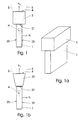
- FIG. 1 shows a first embodiment of a piezoelectric ultrasound transducer which consists of a piezoceramic, plate-shaped lamella 1, which is provided on both sides of its large side surfaces 23 with an electrical contact assignment which is conventional and not shown in more detail.
- this lamella 1 is connected to a rigid cover plate 3.
- the cover plate 3 is of relatively low mass compared to the mass of the piezoceramic vibrating system, consisting of the lamella 1, the electrode assignments mentioned and possibly a further counterplate or sound reflection means, not shown. The possibilities of a low-mass design are discussed in more detail below.
- lamella 1 with n 1 and n-called cover plate 3 with 2 and a respective associated arrow The geometric design of the cover plate 3 is carried out in accordance with the invention in such a way that surface lines 5, which include a sound radiation angle ⁇ , which comprises the structure-borne noise which occurs when the piezoceramic lamella 1 is excited and which enters the cover plate 3 via the surface 21, so that a Surface 4 of the cover plate 3 is covered over the entire surface and homogeneously by the sound.
- the cover plate 3 is preferably designed such that it forms an independently self-oscillating system.
- the cover plate 3 is shaped, for example, by a cuboid configuration with the dimensions (4 ⁇ 5 ⁇ 5) mm.
- a cuboid can, for example, have an inherent resonance frequency of 85 kHz.
- the natural resonance frequency of the piezoceramic lamella 1 assigned to the direction of action can be dimensioned, for example, at 110 kHz.
- Such a converter is preferably operated with a natural resonance of the cover plate, for example 85 kHz, ie the piezo lamella is operated outside of its natural resonance.
- the arrangement and coupling according to the invention it is possible to generate large movement amplitudes of the piezo lamella even outside of their natural resonance and to transmit them to the cover plate, which leads to very large vibration amplitudes of the ultrasound-emitting surface.
- the emitted ultrasonic energy can be increased by a factor of five compared to the prior art based on the radiating surface.
- Operating the piezo louvre outside of its resonance results in very short swing-out times for the transducer.
- the arrangement according to the invention enables additional damping measures of the aforementioned piezo lamella without reducing the ultrasound amplitude.
- FIG. 1 a shows in a perspective view that the overall system described in FIG. 1, depending on the desired directional characteristic or amplitude, can also have a basically any longitudinal extent with a longer slat 1 and a correspondingly dimensioned cover plate 3 perpendicular to the normal directions n 1 and n 2 can.
- FIG. 1b shows a further embodiment of the cover plate 3 in the form of an upside-down truncated pyramid 33, which is connected with its small cover surface to the lamella 1 on its narrow side 21.
- the inclined side surfaces of the truncated pyramid are preferably oriented largely parallel to the surface lines 5 including the angle ⁇ (which is preferably 90 °), as a result of which a uniform and homogeneous detection of the surface 4 by structure-borne noise is achieved.
- This truncated pyramid-like design of the cover plate 3 also leads to a reduction in the resonance frequency, an increase in the radiation or receiver area and thus to an increase in the transmission or reception sensitivity, and to an improvement in the directional characteristic.
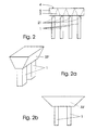
- FIG. 2 shows another basic embodiment according to the invention shown in which several, equally spaced from each other piezoelectric lamellae 1 on their respective narrow sides 21 with a continuous one-piece cover plate 3 are connected.
- the distance the slats 1 should be dimensioned so that the surface 4 of the top surface 3 from structure-borne noise of the piezo lamellae 1 is recorded evenly and homogeneously, as is by dashed lines
- Surface lines 5 is indicated schematically. This arrangement can also be carried out analogously to Fig. 1a. It is also possible as long as the required bending stiffness of the cover plate 3 is not affected is, on the underside of the cover plate several, following the surface lines 5 Make or make recesses or bevels.
- FIGS. 2a and b show a further possible embodiment of FIG. 2, in which the cover plate 33 ', similar to that of Fig. 1b, as in a Dimension of a truncated pyramid is formed.
- the cover plate 33 ' is excited by two Piezoceramic lamellae 1 with the same frequency and phase position are stimulable.
- FIG. 3 shows a further basic embodiment according to the invention, in which a plurality of modular systems designed according to FIG. 1 are used, which are carried by a holder 10, which is preferably arranged in the plane of the center of gravity of the system.
- each of the slats 1 used has its own cover plate 31.
- Such a design is particularly suitable for variable and different control with respect to frequency, phase position and / or amplitude of the individual modules, as a result of which both the beam angle and the beam angle Can generally influence the direction of sound propagation within wide limits.
- By triggering with freely selectable pulse patterns in space and time it is possible to locate bodies in space, determine their distance, size and position, and track their movement.
- FIG. 3a is formed largely analogously to FIG. 3, two modules being assigned a common cover plate 32 here.
- the common cover plate 32 can be made in one piece, or can be produced by gluing two adjacent cover plates 31.
- the advantages that can be achieved in this way correspond to those described for FIG. 3.
- the modules provided in FIGS. 3 and 3a can be spaced equidistantly or from one another, as shown, differently and, as shown in FIG. 3a, can be arranged on curved paths in order to achieve certain focusing effects. It is within the scope of the invention to also design the embodiments described in relation to FIGS. 3 and 3a as a two-dimensional array by means of assemblies shown one behind the other.
- the ultrasound radiation behavior is essentially determined by assemblies the predetermined resonance properties of the cover plates 3, 31, 32, 33, 33 'determined, so that the piezoceramic (s) lamella (s) 1 also outside, but above all below that assigned to their direction of action Resonance frequency is (are) operable without a disturbing or that Ultrasound amplitude loss becoming ineffective to show how this corresponds to known designs of the state technology is the case.
- Another significant advantage of the invention which is based on the fact that the created according to the invention Arrangements below the resonance frequency of the piezoelectric Excitation systems are operable, is that in order to same To be able to deliver ultrasonic power, the respective designs a factor of ten less than equivalent according to the prior art are executable.
- FIG. 4 This design has a massive base plate 6, for example consisting of a ceramic, and a parallel rigid and low-mass cover plate 30, between which a plurality of lamellae 1 made of a homogeneous piezoelectric material are arranged parallel to one another, which form base plate 6 and cover plate 30 run vertically and are connected to them via their narrow sides 22, 21.
- the piezoceramic slats 1 used here are made as thin as possible with respect to their thickness d, which is essentially determined by the mechanical stability still required or the electrical breakdown voltage which should not be exceeded.
- the individual lamellae 1 have dimensions of, for example, (0.2 * 3 * 18) mm, usually more than the number of individual lamellae 1 shown being used.
- the individual lamellae 1 are given a length / height ratio of the order of 5-10.
- the heights and lengths mentioned which essentially determine the respective natural resonance frequencies of the transducer, in no way limit the invention to only that.
- the specific design regulations depend solely on the desired transducer properties, such as working frequency, size, sound amplitude, from which a large number conceivable embodiments resulting from the invention results.
- a thin, approximately 0.3 mm thick disk made of glass, silicon, ceramic or a suitable plastic, which can be selected in accordance with the required bending stiffness and low mass, can be considered for the above-mentioned cover plate 30.
- cellular materials which due to their extremely low mass can be made thicker and therefore more rigid, can be used advantageously.
- the piezoceramic lamellae 1 can be provided in a direction n 3 , which are perpendicular to the normal directions n 2 and n 1 with lengths that differ from one another, which, as shown in the example in FIG. 5, correspond to the tendon lengths of a tendon array measured in a dashed ellipse, or a circle.
- the respective individual lamellae 1 can be divided into sections 11, 12 of different lengths in the direction n 3 , as is schematically indicated in FIG. 6.
- a transducer designed according to the above dimensioning information according to FIG. 4 has, for example, basic resonance frequencies at 50 kHz or 210 kHz.
- Such a transducer is designed to emit and receive air ultrasonic waves in a wide frequency range outside of its natural resonance points. Since it shows very little ringing in this operating mode, it is also very suitable for measurements of extremely short distances and for information transfer. All slats 1 are excited in phase with the same frequency and amplitude.
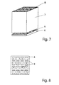
- FIG. 7 Another way of training accordingly thinner piezoceramic lamellae 1 is not to scale in FIG. 7, shown schematically.
- This representation like that of one Base plate 6 according to FIG. 8, does not correspond to that in practice existing conditions and serves only the descriptive Explanation.
- the cavities 8 their number in reality at one Dimension of the hollow body of, for example, (20 ⁇ 20 ⁇ 5) mm is approximately 50, are each with a metallic, not shown Contact assignment assignment, which makes the as slats remaining, for example 0.3 mm thick ceramic webs can be polarized.
- a checkerboard-like shown in more detail in Fig. 8 with corresponding base plate 9 provided with electrodes 9, with said hollow body 7 is to be connected on its bottom surface.
- the Contacting the respective electrodes 9 with each other and with the respective contact assignments of the cavities 8 is for the sake of Clarity not shown.
- the base plate 6 provided an end face of the hollow body 7 is on the opposite end surface again with a cover plate 3 or Cover plate 30 according to the previous embodiments provided without this measure is shown in Fig. 7 in more detail.
- Transducer designed according to this embodiment is mechanical particularly stable, economical and advantageous to manufacture, and can be in use the same way as described so far.
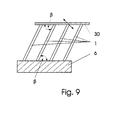
- FIG. 9 is shown schematically in FIG. 9, which is essentially analogous to FIG. 4, but in which the single lamellae 1 used in relation to a used Cover plate 30 and to a base plate 6 at an angle ⁇ , with ⁇ ⁇ 90 °, are arranged.
- the slats 1 are in shape So-called bending vibrator formed, which, for example, according to the State of the art, by two differently polarized Ceramic layers can be realized.
- Such bending vibrators deliver in generally much larger amplitudes.
- Such an arrangement is acoustically particularly "soft" and therefore has an even better one Coupling behavior, for example in air, than that described so far Embodiments and can therefore particularly as a sound receiving Find converters.
- the direction of vibration that the Cover plate 30 follows, is indicated in Fig. 9 by a double arrow.
Landscapes
- Chemical & Material Sciences (AREA)
- Engineering & Computer Science (AREA)
- Ceramic Engineering (AREA)
- Materials Engineering (AREA)
- Structural Engineering (AREA)
- Organic Chemistry (AREA)
- Physics & Mathematics (AREA)
- Acoustics & Sound (AREA)
- Signal Processing (AREA)
- Mechanical Engineering (AREA)
- Transducers For Ultrasonic Waves (AREA)
Description
Will man, z.B. zu Laufzeitmessungen, kurze Schallimpulse emittieren, so muß entweder die Wandlerresonanz stark bedämpft werden, oder der Wandler muß unterhalb seiner niedrigsten Resonanzfrequenz betrieben werden. Bei einlagigen Dickenschwingern sind dann der erreichbaren Schallamplitude der den Schall abstrahlenden Fläche enge Grenzen gesetzt, da die erforderlichen Anregungsspannungen sehr hoch werden.
Die abgestrahlte Ultraschallenergie kann bezogen auf die abstrahlende Fläche etwa um einen Faktor fünf, gegenüber dem Stand der Technik, erhöht werden.
Der Betrieb der Piezolamelle außerhalb deren Resonanz bewirkt sehr kurze Ausschwingzeiten des Wandlers. Außerdem ermöglicht die erfindungsgemäße Anordnung zusätzliche Dämpfungsmaßnahmen ausschließlich genannter Piezolamelle, ohne eine Verringerung der Ultraschallamplitude zu bewirken.
Figur 1b zeigt eine weitere Ausgestaltung der Deckplatte 3 in Form eines auf dem Kopf stehenden Pyramidenstumpfes 33, der mit seiner kleinen Deckfläche mit genannter Lamelle 1 an deren Schmalseite 21 verbunden ist. Die geneigten Seitenflächen des Pyramidenstumpfes sind dabei bevorzugt weitestgehend parallel zu genannten, den Winkel α (welcher bevorzugt 90° beträgt) einschließenden Mantellinien 5 ausgerichtet, wodurch eine gleichmäßige und homogene Erfassung der Oberfläche 4 durch den Körperschall erreicht wird. Diese pyramidenstumpfartige Ausbildung der Deckplatte 3 führt weiterhin zu einer Reduzierung der Resonanzfrequenz, einer Vergrößerung der Abstrahl- bzw. Empfängerfläche und damit zu einer Vergrößerung der Sende- bzw. Empfangsempfindlichkeit, sowie zu einer Verbesserung der Richtcharakteristik.
Durch Ansteuerung mit beliebig wählbaren Impulsmustern in Raum und Zeit ist es prinzipiell möglich, Körper im Raum zu orten, ihre Entfernung, Größe und Lage zu bestimmen sowie ihre Bewegung zu verfolgen.
Weitestgehend analog zu Fig. 3 ist eine Ausführung gemäß Fig. 3a ausgebildet, wobei hier zwei Modulen eine gemeinsame Deckplatte 32 zugewiesen ist. Die gemeinsame Deckplatte 32 kann dabei einstückig ausgeführt, oder durch Verkleben zweier benachbarter Deckplatten 31 hergestellt sein. Die hiermit erreichbaren Vorteile entsprechen denen zu Fig. 3 beschriebenen. Je nach Verwendungszweck können die in den Figuren 3 und 3a vorgesehenen Module äquidistant oder untereinander, wie dargestellt, unterschiedlich beabstandet und, wie in Fig. 3a dargestellt, auf gekrümmten Bahnen angeordnet sein, um bestimmte Fokussierungseffekte zu erzielen.
Es liegt im Rahmen der Erfindung, auch die zu den Figuren 3 und 3a beschriebenen Ausführungen auch als flächenhaftes Array durch mehrfache Hintereinanderordnung dargestellter Baugruppen auszubilden.
Eine dieser weiteren grundlegenden Ausführungsformen soll anhand einer schematischen Ausführung gemäß Fig. 4 beschrieben werden.
Diese Ausbildung weist eine massereiche Grundplatte 6, bspw. aus einer Keramik bestehend, und ein dazu parallel angeordnetes biegesteifes und massearmes Deckplättchen 30 auf, zwischen denen zueinander parallel eine Mehrzahl von Lamellen 1 aus einem homogenen piezoelektrischen Material angeordnet sind, die zu Grundplatte 6 und Deckplättchen 30 senkrecht verlaufen und über ihre Schmalseiten 22, 21 mit diesen verbunden sind. Zwischen den Lamellen 1 verbleibt jeweils ein Freiraum der Ausdehnung a, der in der Größenordnung eines Zehnfachen der Einzellamellendicke d in gleicher Richtung festgelegt ist. Die hier eingesetzten piezokeramischen Lamellen 1 sind bzgl. ihrer Dicke d möglichst dünn ausgeführt, was im wesentlichen durch die noch erforderliche mechanische Stabilität bzw. die nicht zu überschreitende elektrische Durchbruchspannung bestimmt ist. Für typische praktische Ausführungen haben die Einzellamellen 1 dabei Abmessungen von bspw. (0,2 · 3 · 18) mm, wobei in der Regel mehr als die dargestellte Anzahl einzelner Lamellen 1 zum Einsatz gelangen. Den Einzellamellen 1 ist dabei insbesondere ein Längen/Höhen-Verhältnis in der Größenordnung von 5 - 10 gegeben. Die genannten Höhen und Längen, welche im wesentlichen die jeweiligen Eigenresonanzfrequenzen des Wandlers bestimmen, beschränken die Erfindung jedoch in keinem Fall nur darauf, Die jeweils konkreten Bemessungsvorschriften hängen einzig von den gewünschten Wandlereigenschaften, wie z.B. Arbeitsfrequenz, Größe, Schallamplitude, ab, woraus eine Vielzahl denkbarer, unter die Erfindung fallender Ausführungsformen resultiert.
Für genanntes Deckplättchen 30 kommt im Ausführungsbeispiel gemäß Fig. 4 bspw. eine dünne, ca. 0,3 mm dicke Scheibe aus Glas, Silizium, Keramik oder einem geeigneten Kunststoff in Betracht, die nach der Maßgabe der erforderlichen Biegesteifheit und geringen Masse auswählbar ist. Auch in dieser Bauform sind, ebenso wie in den zuvor beschriebenen, zellular aufgebaute Materialien, die aufgrund ihrer extrem geringen Masse dicker und damit biegesteifer aufgebaut werden können, vorteilhaft einsetzbar. Zur Unterdrückung etwaiger unerwünschter Querresonanzen können die piezokeramischen Lamellen 1 in einer Richtung n3, die senkrecht zu den Normalenrichtungen n2 und n1 mit voneinander unterschiedlichen Längen vorgesehen sein, welche sich, wie im Beispiel der Fig. 5 dargestellt, entsprechend der Sehnenlängen einer Sehnenschar in einer strichliniert dargestellten Ellipse, oder eines Kreises, bemessen. Ebenso können bei einer gewünschten rechteckförmigen Anordnung die jeweiligen Einzellamellen 1 in Teilstücke 11, 12 unterschiedlicher Länge in Richtung n3 unterteilt sein, wie es in Fig. 6 schematisch angedeutet ist.
Ein entsprechend obiger Dimensionierungsangaben ausgebildeter Wandler gemäß Fig. 4 besitzt bspw. Grundresonanzfrequenzen bei 50 kHz bzw. 210 kHz. Ein solcher Wandler ist zum Abstrahlen und zum Empfang von Luftultraschallwellen in einem breiten Frequenzspektrum außerhalb seiner Eigenresonanzstellen ausgelegt. Da er in dieser Betriebsart nur äußerst geringe Nachschwingerscheinungen zeigt, ist er auch zu Messungen extrem kurzer Distanzen sowie zur Informationsübertragung sehr gut geeignet. Dabei werden alle Lamellen 1 gleichphasig mit gleicher Frequenz und Amplitude angeregt.
- 1, 11, 12
- piezoelektrische Lamelle
- 21,22
- Schmalseiten einer piezoelektrischen Lamelle
- 23
- große Seitflächen
- 3, 31, 32
- Deckplatte
- 33, 33'
- Deckplatte als Pyramidenstumpf, -dach
- 30
- Deckplättchen
- 4
- schallabstrahlende bzw. empfangende Oberfläche
- 5
- Mantellinien
- α
- Schallabstrahlwinkel
- 6
- Grundplatte
- 7
- piezokeramischer Hohlkörper
- 8
- wabenförmiger Hohlraum
- 9
- schachbrettartige Kontaktierungsbelegung
- 10
- Halterung
- n1
- Lamellennormale
- n2
- Deckplatten- bzw. Deckplättchennormale
- n3
- Normalenrichtung senkrecht zu n1 und n2
- β
- Biegebalkenneigungswinkel
- a
- Lamellenabstand
- d
- Lamellendicke
Claims (14)
- Piezoelektrischer Ultraschallwandler mit anpaßbarer Schallkenn-Impedanz bestehend aus wenigstens einer, an ihren großen Seitflächen mit Elektroden versehenen Lamelle aus piezokeramischen Material, welche im d31-Modus betreibbar ist, wenigstens einer schallabstrahlenden und/oder empfangenden Fläche, wobei der Masseschwerpunkt des Gesamtwandlersystems weitab der schallabgebenden bzw. -empfangenden Oberfläche (4) gelegt ist, dadurch gekennzeichnet, daßwobei die Eigenresonanzfrequenzen der wenigstens einen piezokeramischen Lamelle (1) und der schallabstrahlenden und/oder -empfangenden Deckplatte zueinander deutlich unterschiedlich festlegbar sind.wenigstens eine Lamelle (1) vorgesehen ist, die an einer ihrer Schmalseiten (21) mit wenigstens einer geometrisch variabel anpaßbaren, biegesteifen und in bezug auf die Gesamtwandler- bzw. Lamellenmasse massearmen Deckplatte (30; 3, 31, 32, 33, 33'), die bezüglich der ihr zugewiesenen geometrischen Bemessung so ausgebildet und mit kleiner Ankoppelfläche an die Schmalseite der Lamelle (1) angebunden ist, daß sie ein selbständig eigenschwingungsfähiges System bildet, derart verbunden ist,daß zumindest im Fall eines schallabgebenden Betriebes die gesamte Oberfläche (4) der Deckplatte (3, 31, 32, 33, 33') durch Mantellinien (5) eines Abstrahlwinkels (α), mit denen die piezoelektrische Lamelle (1) in genannte Deckplatte (3, 31, 32, 33, 33') einstrahlt, möglichst vollständig erfaßt ist undeinzig dieser Oberfläche (4) die Funktion der schallabstrahlenden und/oder -empfangenden Fläche zugewiesen ist,
- Piezoelektrischer Ultraschallwandler gemäß Anspruch 1, dadurch gekennzeichnet, daß die Geometrie der Deckplatte (3, 31, 32, 33, 33') zumindest in ihrer äußeren Deckplattenberandung dem Abstrahlwinkel (α) der Lamelle(n) im wesentlichen folgend festgelegt ist.
- Piezoelektrischer Ultraschallwandler gemäß Anspruch 1 oder 2, dadurch gekennzeichnet, daß mehreren zueinander parallel angeordneten und voneinander beabstandeten piezoelektrischen Lamellen (1) an ihren jeweiligen Schmalseiten (21) eine gemeinsame einstückige Deckplatte (30; 3, 32, 33, 33') zugewiesen ist.
- Piezoelektrischer Ultraschallwandler gemäß Anspruch 1 oder 2, dadurch gekennzeichnet, daß mehreren zueinander parallel angeordneten und voneinander beabstandeten piezoelektrischen Lamellen (1) an ihren jeweiligen Schmalseiten (21) jeweils eine separate Deckplatte (31, 33) zugewiesen ist.
- Piezoelektrischer Ultraschallwandler gemäß Anspruch 4, dadurch gekennzeichnet, daß ein Teil benachbarter Deckplatten (31, 33') teilweise miteinander verbunden und insbesondere als einstückige Deckplatte (32, 33') ausgebildet ist.
- Piezoelektrischer Ultraschallwandler gemäß einem der Ansprüche 1 bis 5, dadurch gekennzeichnet, daß für das Material der Deckplatte(n) (3, 31, 32, 33, 33') eins mit vorgebbarer Schallkenn-Impedanz ausgewählt ist, welches vorzugsweise aus in Harz eingebetteten Hohlkugeln besteht.
- Piezoelektrischer Ultraschallwandler gemäß einem der Ansprüche 1 bis 6, dadurch gekennzeichnet, daß die Normalen (n1) der piezoelektrischen Lamelle(n) (1) und die Normalen (n2) der Deckplatte(n) (30; 3, 31, 32, 33, 33') zueinander senkrecht stehend angeordnet sind.
- Piezoelektrischer Ultraschallwandler gemäß Anspruch 1, dadurch gekennzeichnet, daß genannter Masseschwerpunkt des Gesamtsystems durch eine massereiche Grundplatte (6) in das Gebiet mehrerer zueinander beabstandeter, benachbart angeordneter piezoelektrischer Einzellamellen (1) verlegt ist und die piezoelektrischen Lamellen an ihren gegenüberliegenden Schmalseiten (22, 21) mit genannter Grundplatte (6) bzw. einem einstückigen dünnen Deckplättchen (30) verbunden sind.
- Piezoelektrischer Ultraschallwandler gemäß Anspruch 8, dadurch gekennzeichnet, daß genannte Einzellamellen in ihrer Dicke (d) so dünn ausgeführt sind, wie es die mechanische Stabilität und/oder die elektrische Durchbruchspannung zuläßt und ihr gegenseitiger Abstand (a) in der Größenordnung des Zehnfachen genannter Dicke (d) festgelegt ist.
- Piezoelektrischer Ultraschallwandler gemäß Anspruch 8 und/oder 9, dadurch gekennzeichnet, daß genannte Einzellamellen (1) als parallel zueinander angeordnete piezoelektrische Biegeschwinger ausgebildet sind, die in bezug zu genanntem Deckplättchen (30) und genannter Grundplatte (6) einen Winkel (β), mit β < 90°, einschließen.
- Piezoelektrischer Ultraschallwandler gemäß einem der Ansprüche 8 bis 10, dadurch gekennzeichnet, daß den piezoelektrischen Lamellen (1) in einer Richtung zur Normalenrichtung (n1) der Lamellen und zur Normalenrichtung (n2) des Deckplättchens (30) senkrecht verlaufenden Richtung (n3) voneinander verschiedene Längen gegeben sind, deren Bemessung insbesondere einer Sehnenlänge einer Sehnenschar in einer Ellipse folgt.
- Piezoelektrischer Ultraschallwandler gemäß einem der Ansprüche 8 bis 10, dadurch gekennzeichnet, daß die piezoelektrischen Einzellamellen einer in Richtung zur Normalenrichtung (n1) der Lamellen und zur Normalenrichtung (n2) des Deckplättchens (30) senkrecht verlaufenden Richtung (n3) zumindest teilweise als unterbrochene Lamellen (11 ,12) unterschiedliche Länge ausgeführt sind.
- Piezoelektrischer Ultraschallwandler gemäß einem der Ansprüche (1 bis 7) oder 8, dadurch gekennzeichnet, daß die piezoelektrischen Lamellen (1) durch einen stranggepreßten piezokerarnischen Hohlkörper (7) mit wabenförmig verteilten Hohlräumen (8), die mit einer elektrischen Innenkontaktierung versehen sind, gebildet sind, wobei Mittel vorgesehen sind, die aneinanderfolgende Waben (7) alternierend polarisieren.
- Piezoelektrischer Ultraschallwandler gemäß Anspruch 13, dadurch gekennzeichnet, daß genannte Mittel zur unterschiedlichen Polarisation durch eine, mit genannten wabenförmigen Hohlräumen (8) folgende schachbrettartige Kontaktierungsbelegung (9) versehenen Grundplatte (6) gebildet sind.
Applications Claiming Priority (3)
| Application Number | Priority Date | Filing Date | Title |
|---|---|---|---|
| DE19512417 | 1995-04-03 | ||
| DE19512417A DE19512417C2 (de) | 1995-04-03 | 1995-04-03 | Piezoelektrischer Ultraschallwandler |
| PCT/EP1996/001445 WO1996031870A1 (de) | 1995-04-03 | 1996-04-02 | Piezoelektrischer ultraschallwandler |
Publications (2)
| Publication Number | Publication Date |
|---|---|
| EP0763232A1 EP0763232A1 (de) | 1997-03-19 |
| EP0763232B1 true EP0763232B1 (de) | 2001-11-14 |
Family
ID=7758646
Family Applications (1)
| Application Number | Title | Priority Date | Filing Date |
|---|---|---|---|
| EP96909167A Expired - Lifetime EP0763232B1 (de) | 1995-04-03 | 1996-04-02 | Piezoelektrischer ultraschallwandler |
Country Status (5)
| Country | Link |
|---|---|
| US (1) | US5761156A (de) |
| EP (1) | EP0763232B1 (de) |
| JP (1) | JP3541322B2 (de) |
| DE (1) | DE19512417C2 (de) |
| WO (1) | WO1996031870A1 (de) |
Families Citing this family (14)
| Publication number | Priority date | Publication date | Assignee | Title |
|---|---|---|---|---|
| WO2002008773A2 (en) * | 2000-07-19 | 2002-01-31 | Orbotech Ltd. | Apparatus and method for electrical testing of electrical circuits |
| EP1418835A2 (de) * | 2001-07-24 | 2004-05-19 | Sunlight Medical, Ltd. | Verfahren und gerät für die knochendiagnose |
| JP2004535882A (ja) * | 2001-07-24 | 2004-12-02 | サンライト メディカル リミテッド | 超音波を用いた骨年齢評価方法 |
| DE10361316B4 (de) * | 2003-12-19 | 2015-08-27 | Valeo Schalter Und Sensoren Gmbh | Ultraschallwandlervorrichtung |
| DE102004026196A1 (de) * | 2004-05-28 | 2005-12-29 | Valeo Schalter Und Sensoren Gmbh | Verfahren, Vorrichtung und Sensormodul zum Messen des Abstandes zwischen einem Fahrzeug und einem Hindernis |
| WO2008157616A2 (en) * | 2007-06-18 | 2008-12-24 | The Penn State Research Foundation | Acoustic transducer |
| USD611075S1 (en) | 2007-08-08 | 2010-03-02 | Honeywell International Inc. | Saw sensor button package |
| WO2011162002A1 (ja) | 2010-06-25 | 2011-12-29 | 京セラ株式会社 | 音響発生器 |
| WO2012172136A1 (es) * | 2011-06-14 | 2012-12-20 | Universidad De Granada | Transductor de ondas de torsión |
| JP5928151B2 (ja) | 2012-05-21 | 2016-06-01 | セイコーエプソン株式会社 | 超音波トランスデューサー、超音波プローブ、診断装置および電子機器 |
| ES2602508B1 (es) | 2015-07-16 | 2017-11-30 | Universidad De Granada | Dispositivo emisor de ondas ultrasónicas de torsión y transductor que lo comprende |
| CN108296154B (zh) * | 2017-08-07 | 2023-12-05 | 雷索智能科技(苏州)有限公司 | 超声波振动机构及超声波振动装置 |
| CN111473839B (zh) * | 2020-04-22 | 2022-02-22 | 中电科技集团重庆声光电有限公司 | 一种超声换能器及其嵌套结构 |
| CN112865604B (zh) * | 2021-03-03 | 2023-03-14 | 国网新疆电力有限公司信息通信公司 | 一种具有宽工作范围的低阻尼驰振式压电风能采集器 |
Family Cites Families (17)
| Publication number | Priority date | Publication date | Assignee | Title |
|---|---|---|---|---|
| US4219889A (en) * | 1960-09-16 | 1980-08-26 | The United States Of America As Represented By The Secretary Of The Navy | Double mass-loaded high power piezo-electric underwater transducer |
| US3370186A (en) * | 1965-02-05 | 1968-02-20 | Blackstone Corp | Ultrasonic transducers |
| US4231112A (en) * | 1970-07-30 | 1980-10-28 | Fred M. Dellorfano, Jr. | High-power underwater transducer with improved performance and reliability characteristics and method for controlling said improved characteristics |
| DE2045152C3 (de) * | 1970-09-11 | 1975-02-06 | Braun Ag, 6000 Frankfurt | Schwingmotor mit bilaminaren Biegeschwingern für elektrisch angetriebene Trockenrasierapparate |
| US4072871A (en) * | 1974-05-20 | 1978-02-07 | Westinghouse Electric Corp. | Electroacoustic transducer |
| US4536862A (en) * | 1982-05-24 | 1985-08-20 | Texas Instruments Incorporated | Seismic cable assembly having improved transducers |
| FR2570916B1 (fr) * | 1983-06-23 | 1988-04-15 | France Etat Armement | Procede et transducteur electro-acoustique pour emettre ou recevoir des ondes acoustiques dans plusieurs bandes passantes |
| US4556814A (en) * | 1984-02-21 | 1985-12-03 | Ngk Spark Plug Co., Ltd. | Piezoelectric ultrasonic transducer with porous plastic housing |
| US4633119A (en) * | 1984-07-02 | 1986-12-30 | Gould Inc. | Broadband multi-resonant longitudinal vibrator transducer |
| JPS6126397A (ja) * | 1984-07-17 | 1986-02-05 | Matsushita Electric Ind Co Ltd | 超音波送受波器 |
| US4471475A (en) * | 1984-09-11 | 1984-09-11 | The United States Of America As Represented By The Secretary Of The Navy | Single element cantilever mounted shear wave transducer |
| US4718046A (en) * | 1985-11-22 | 1988-01-05 | Mobil Oil Corporation | Method for driving a bender-type transmitter of a borehole logging tool to sequentially produce acoustic compressional and tube waves |
| US4735096A (en) * | 1986-08-27 | 1988-04-05 | Xecutek Corporation | Ultrasonic transducer |
| JPH01501421A (ja) * | 1986-11-07 | 1989-05-18 | プレッシー オーストラリア プロプライエタリー リミテッド | 低周波の水中音源として動作する複合ソナートランスジューサ |
| DE3920663A1 (de) * | 1989-06-23 | 1991-01-10 | Siemens Ag | Breitstrahlender ultraschallwandler |
| FR2663182B1 (fr) * | 1990-06-12 | 1992-09-18 | Grosso Gilles | Transducteur electro-acoustique immerge. |
| US5625149A (en) * | 1994-07-27 | 1997-04-29 | Hewlett-Packard Company | Ultrasonic transductor |
-
1995
- 1995-04-03 DE DE19512417A patent/DE19512417C2/de not_active Expired - Lifetime
-
1996
- 1996-04-02 WO PCT/EP1996/001445 patent/WO1996031870A1/de not_active Ceased
- 1996-04-02 JP JP52997596A patent/JP3541322B2/ja not_active Expired - Lifetime
- 1996-04-02 US US08/737,694 patent/US5761156A/en not_active Expired - Lifetime
- 1996-04-02 EP EP96909167A patent/EP0763232B1/de not_active Expired - Lifetime
Also Published As
| Publication number | Publication date |
|---|---|
| US5761156A (en) | 1998-06-02 |
| JPH10501670A (ja) | 1998-02-10 |
| DE19512417A1 (de) | 1996-10-10 |
| JP3541322B2 (ja) | 2004-07-07 |
| EP0763232A1 (de) | 1997-03-19 |
| WO1996031870A1 (de) | 1996-10-10 |
| DE19512417C2 (de) | 1997-02-06 |
Similar Documents
| Publication | Publication Date | Title |
|---|---|---|
| EP0041664B1 (de) | Verfahren zur Herstellung einer Ultraschallwandleranordnung | |
| EP0763232B1 (de) | Piezoelektrischer ultraschallwandler | |
| DE69516055T2 (de) | Ultraschallumwandler | |
| EP0154706B1 (de) | Piezoelektrischer Luft-Ultraschallwandler mit Breitbandcharakteristik | |
| DE68924057T2 (de) | Anordnung von Ultraschallwandlern. | |
| DE3119272A1 (de) | "bogenabtastungs-ultraschallwandler-anordnung" | |
| DE2949930A1 (de) | Elektro-akustischer wandler fuer akustische abbildungseinrichtungen | |
| EP0308931B1 (de) | Ultraschallwandler mit astigmatischer Sende-/Empfangscharakteristik | |
| DE10155894A1 (de) | Piezoelektrische Mehrschichtstruktur mit gleichmässigem elektrischem Feld | |
| DE102015015900B3 (de) | Schwingelement für einen Ultraschall-Transducer mit Mehrfachresonanz | |
| EP0308899A2 (de) | Ultraschallwandler mit astigmatischer Sende-/Empfangscharakteristik | |
| EP0045989B1 (de) | Gerät zur akustischen Impedanzanpassung | |
| DE102015015901B3 (de) | Schwingelement für einen Ultraschall-Transducer mit einer auf einem Translationsgitter basierenden Mehrfachresonanz | |
| EP0222276A2 (de) | Ultraschallprüfkopf | |
| DE102015015903B3 (de) | Schwingelement für einen Ultraschall-Transducer mit einer auf einer Rotationsperiodizität basierenden Mehrfachresonanz | |
| DE3215242C2 (de) | ||
| EP3010653A1 (de) | Elektroakustischer wandler | |
| EP1005691A1 (de) | Schallwandler | |
| DE102017209823A1 (de) | Ultraschallsensor | |
| EP0478611B1 (de) | Breitstrahlender ultraschallwandler | |
| DE19922965C2 (de) | Anordnung von mikromechanischen Ultraschallwandlern | |
| DE19833213C2 (de) | Ultraschall-Sendeanordnung | |
| DE102008049541A1 (de) | Ultraschallwandler mit mindestens einem vollaktiven, monolithischen Piezoelement, Verfahren zum Kontaktieren des Ultraschallwandlers mittels photostrukturierter Isolationsschicht und Verwendung des Ultraschallwandlers | |
| JPS62261300A (ja) | 超音波探触子用複合圧電材 | |
| DE2100473B2 (de) | Elektroakustischer Wandler |
Legal Events
| Date | Code | Title | Description |
|---|---|---|---|
| PUAI | Public reference made under article 153(3) epc to a published international application that has entered the european phase |
Free format text: ORIGINAL CODE: 0009012 |
|
| 17P | Request for examination filed |
Effective date: 19961129 |
|
| AK | Designated contracting states |
Kind code of ref document: A1 Designated state(s): FR GB IT NL |
|
| GRAG | Despatch of communication of intention to grant |
Free format text: ORIGINAL CODE: EPIDOS AGRA |
|
| GRAG | Despatch of communication of intention to grant |
Free format text: ORIGINAL CODE: EPIDOS AGRA |
|
| GRAH | Despatch of communication of intention to grant a patent |
Free format text: ORIGINAL CODE: EPIDOS IGRA |
|
| 17Q | First examination report despatched |
Effective date: 20010215 |
|
| GRAH | Despatch of communication of intention to grant a patent |
Free format text: ORIGINAL CODE: EPIDOS IGRA |
|
| GRAA | (expected) grant |
Free format text: ORIGINAL CODE: 0009210 |
|
| AK | Designated contracting states |
Kind code of ref document: B1 Designated state(s): FR GB IT NL |
|
| REG | Reference to a national code |
Ref country code: GB Ref legal event code: IF02 |
|
| GBT | Gb: translation of ep patent filed (gb section 77(6)(a)/1977) |
Effective date: 20020122 |
|
| PLBE | No opposition filed within time limit |
Free format text: ORIGINAL CODE: 0009261 |
|
| STAA | Information on the status of an ep patent application or granted ep patent |
Free format text: STATUS: NO OPPOSITION FILED WITHIN TIME LIMIT |
|
| 26N | No opposition filed | ||
| PGFP | Annual fee paid to national office [announced via postgrant information from national office to epo] |
Ref country code: GB Payment date: 20140422 Year of fee payment: 19 |
|
| PGFP | Annual fee paid to national office [announced via postgrant information from national office to epo] |
Ref country code: IT Payment date: 20140430 Year of fee payment: 19 Ref country code: FR Payment date: 20140422 Year of fee payment: 19 |
|
| PGFP | Annual fee paid to national office [announced via postgrant information from national office to epo] |
Ref country code: NL Payment date: 20150420 Year of fee payment: 20 |
|
| GBPC | Gb: european patent ceased through non-payment of renewal fee |
Effective date: 20150402 |
|
| PG25 | Lapsed in a contracting state [announced via postgrant information from national office to epo] |
Ref country code: IT Free format text: LAPSE BECAUSE OF NON-PAYMENT OF DUE FEES Effective date: 20150402 Ref country code: GB Free format text: LAPSE BECAUSE OF NON-PAYMENT OF DUE FEES Effective date: 20150402 |
|
| REG | Reference to a national code |
Ref country code: FR Ref legal event code: ST Effective date: 20151231 |
|
| PG25 | Lapsed in a contracting state [announced via postgrant information from national office to epo] |
Ref country code: FR Free format text: LAPSE BECAUSE OF NON-PAYMENT OF DUE FEES Effective date: 20150430 |
|
| REG | Reference to a national code |
Ref country code: NL Ref legal event code: MK Effective date: 20160401 |