EP0763373A1 - Einspuriger Rollschuh - Google Patents
Einspuriger Rollschuh Download PDFInfo
- Publication number
- EP0763373A1 EP0763373A1 EP96810546A EP96810546A EP0763373A1 EP 0763373 A1 EP0763373 A1 EP 0763373A1 EP 96810546 A EP96810546 A EP 96810546A EP 96810546 A EP96810546 A EP 96810546A EP 0763373 A1 EP0763373 A1 EP 0763373A1
- Authority
- EP
- European Patent Office
- Prior art keywords
- discs
- frame
- skate according
- support
- caster
- Prior art date
- Legal status (The legal status is an assumption and is not a legal conclusion. Google has not performed a legal analysis and makes no representation as to the accuracy of the status listed.)
- Withdrawn
Links
- 235000004443 Ricinus communis Nutrition 0.000 claims description 4
- 230000006835 compression Effects 0.000 claims description 3
- 238000007906 compression Methods 0.000 claims description 3
- 229920002994 synthetic fiber Polymers 0.000 claims description 2
- 240000000528 Ricinus communis Species 0.000 description 3
- 230000000694 effects Effects 0.000 description 3
- 229910000906 Bronze Inorganic materials 0.000 description 1
- 239000010974 bronze Substances 0.000 description 1
- KUNSUQLRTQLHQQ-UHFFFAOYSA-N copper tin Chemical compound [Cu].[Sn] KUNSUQLRTQLHQQ-UHFFFAOYSA-N 0.000 description 1
- 230000007423 decrease Effects 0.000 description 1
- 230000001419 dependent effect Effects 0.000 description 1
- 239000013536 elastomeric material Substances 0.000 description 1
- 238000010438 heat treatment Methods 0.000 description 1
- 210000000003 hoof Anatomy 0.000 description 1
- 230000003100 immobilizing effect Effects 0.000 description 1
- 230000001788 irregular Effects 0.000 description 1
- 239000000463 material Substances 0.000 description 1
- 239000002184 metal Substances 0.000 description 1
- 229920003023 plastic Polymers 0.000 description 1
- 239000004033 plastic Substances 0.000 description 1
- 229920002635 polyurethane Polymers 0.000 description 1
- 239000004814 polyurethane Substances 0.000 description 1
- 230000000717 retained effect Effects 0.000 description 1
- 238000005096 rolling process Methods 0.000 description 1
- 125000006850 spacer group Chemical group 0.000 description 1
- 229910001220 stainless steel Inorganic materials 0.000 description 1
- 239000010935 stainless steel Substances 0.000 description 1
Images


Classifications
-
- A—HUMAN NECESSITIES
- A63—SPORTS; GAMES; AMUSEMENTS
- A63C—SKATES; SKIS; ROLLER SKATES; DESIGN OR LAYOUT OF COURTS, RINKS OR THE LIKE
- A63C17/00—Roller skates; Skate-boards
- A63C17/04—Roller skates; Skate-boards with wheels arranged otherwise than in two pairs
- A63C17/06—Roller skates; Skate-boards with wheels arranged otherwise than in two pairs single-track type
- A63C17/061—Roller skates; Skate-boards with wheels arranged otherwise than in two pairs single-track type with relative movement of sub-parts on the chassis
- A63C17/062—Roller skates; Skate-boards with wheels arranged otherwise than in two pairs single-track type with relative movement of sub-parts on the chassis with a pivotal frame or cradle around transversal axis for relative movements of the wheels
-
- A—HUMAN NECESSITIES
- A63—SPORTS; GAMES; AMUSEMENTS
- A63C—SKATES; SKIS; ROLLER SKATES; DESIGN OR LAYOUT OF COURTS, RINKS OR THE LIKE
- A63C17/00—Roller skates; Skate-boards
- A63C17/04—Roller skates; Skate-boards with wheels arranged otherwise than in two pairs
- A63C17/06—Roller skates; Skate-boards with wheels arranged otherwise than in two pairs single-track type
- A63C17/065—Roller skates; Skate-boards with wheels arranged otherwise than in two pairs single-track type with movements during use of the foot plate or shoe relative to the chassis, e.g. inline clap skate
-
- A—HUMAN NECESSITIES
- A63—SPORTS; GAMES; AMUSEMENTS
- A63C—SKATES; SKIS; ROLLER SKATES; DESIGN OR LAYOUT OF COURTS, RINKS OR THE LIKE
- A63C17/00—Roller skates; Skate-boards
- A63C17/14—Roller skates; Skate-boards with brakes, e.g. toe stoppers, freewheel roller clutches
- A63C17/1409—Roller skates; Skate-boards with brakes, e.g. toe stoppers, freewheel roller clutches contacting one or more of the wheels
- A63C17/1418—Roller skates; Skate-boards with brakes, e.g. toe stoppers, freewheel roller clutches contacting one or more of the wheels with radial movement against the roll surface of the wheel
-
- A—HUMAN NECESSITIES
- A63—SPORTS; GAMES; AMUSEMENTS
- A63C—SKATES; SKIS; ROLLER SKATES; DESIGN OR LAYOUT OF COURTS, RINKS OR THE LIKE
- A63C17/00—Roller skates; Skate-boards
- A63C17/14—Roller skates; Skate-boards with brakes, e.g. toe stoppers, freewheel roller clutches
- A63C17/1409—Roller skates; Skate-boards with brakes, e.g. toe stoppers, freewheel roller clutches contacting one or more of the wheels
- A63C17/1427—Roller skates; Skate-boards with brakes, e.g. toe stoppers, freewheel roller clutches contacting one or more of the wheels the brake contacting other wheel associated surfaces, e.g. hubs, brake discs or wheel flanks
Definitions
- the subject of the present invention is an in-line roller skate comprising at least three rollers, the rear caster and at least one other caster being mounted on a frame articulated on a shoe support around an axis parallel to the axes of the rollers, a brake integral with said support and acting at least on the rear caster during tilting of the shoe support towards the rear and limited resistance retaining means opposing the tilting of the shoe support towards the rear.
- Inline skates are generally equipped at the rear with a brake shoe which brakes by friction on the ground when the skater tips back on the rear caster.
- the braking obtained is dependent on the nature of the ground. It is irregular and is accompanied by unpleasant vibrations.
- the hoof also forms, at the rear of the skate, a protuberance which can be troublesome on uneven ground, in particular when descending a step or a sidewalk.
- This shoe comprises a platform resiliently mounted on four wheels mounted in pairs on independent oscillating supports.
- the platform is provided at the rear with a brake shoe braking directly on the rear wheel.
- the tilting axis of the platform coincides with the axis of the rear swinging support.
- a similar pad is described in US Patent 1,342,071.
- the object of the invention is to avoid replacing the brake shoes and to increase the effectiveness of the brake.
- the roller skate according to the invention is characterized in that the brake consists of at least one pair of opposite coaxial discs each having an at least approximately frustoconical face intended to come into contact with one side of the caster.
- the discs can be completely immobilized and brake the caster by friction on the caster itself, or they can be driven by the caster and brake by friction on a brake lining.
- the discs can advantageously be immobilized in different angular positions, so that the part of the discs in contact with the roller can be modified.
- the area of the discs in contact with the caster constantly changes.
- the discs are driven by the wheel and their faces opposite to the frustoconical faces are in contact with a brake lining fixed to the frame or to an auxiliary support carrying the two rear rollers or are provided a brake lining rubbing on the frame or the auxiliary support carrying the rear casters.
- braking takes place in part by friction on the brake lining so that the heating at the level of the wheel is less and the dissipation of heat at the level of the linings is ensured by the frame, respectively the support of the rear castors.
- the sliding of the discs on the caster can also be greatly reduced by forming in the frustoconical faces of the discs a kind of toothing in the form of cells matching the shape of the caster so that the discs are more easily driven by the caster.
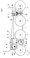
- Figure 1 is a side view, partially in axial section, of a first embodiment.
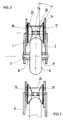
- Figure 2 is a partial sectional view along II-II of Figure 1, in the rolling position.
- Figure 3 is a view similar to Figure 2 in the braking position.
- Figure 4 is a view similar to Figure 2 which illustrates a second embodiment.
- FIG. 5 shows this second embodiment in the braking position.
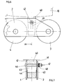
- FIG. 6 represents an alternative embodiment of the means for retaining the shoe support on the frame.
- Figure 7 is a sectional view along VII-VII of Figure 6.
- Figure 8 shows a third embodiment.
- FIG. 9 is a partial sectional view along IX-IX of FIG. 8.
- the inline skate shown in Figures 1 and 2 comprises a frame consisting of two parallel plates 1 and 2 between which are mounted four inline wheels 3, 4, 5, 6 mounted on ball bearings on axes such as axis 7.
- the plates 1 and 2 are kept apart from the rollers by spacers 8 and 9 bearing on the inner rings of the ball bearings.
- the skate comprises a shoe 10 fixed on a platform to which are fixed, at the rear, a support 11 and, at the front, a stud 12.
- the support 11 has two vertical wings 13 and 14 engaged between the plates 1 and 2 of the frame.
- the support 11 is articulated on the frame 1, 2 by means of an axis 15 located between the two rear casters 5 and 6, between the axes of these casters and the shoe 10.
- Between the wings 13 and 14 of the support 11 are in further mounted two identical pairs of discs 16, 17 and 18, 19.
- the pair of discs 16, 17 is mounted on an axis 20 consisting of a screw with two threads of opposite direction screwed respectively into each of the discs 16 and 17. From same, the pair of discs 18, 19 is mounted on an identical screw 21.
- the screws 20 and 21 rotate freely in the support 11.
- the axes of the screws 20 and 21 are at the same distance from the axis 15 and the distance between the axis of the screw 20 and the caster 6 is the same as the distance between the axis of the screw 21 and the caster 5.
- the discs have a frustoconical face 22 facing the rollers and they are furthermore provided with holes 23 distributed regularly and circularly on the disc. These holes allow immobilization of the rotating discs by means of a bar 24, respectively 25 passing through the pair of discs and the wings 13 and 14 of the support.
- a screw 26 is engaged between the head of which and a washer 27 is disposed a precompressed spring 28.
- a washer 27 is disposed between the washer 27 and the stud 12 between the washer 27 and the stud 12 .
- pinched two pins 29 and 30 connecting the plates 1 and 2 of the frame.
- the front of the shoe is thus retained elastically to the frame, the resistance to tilting around the axis 15 can be adjusted by modifying the precompression of the spring 28 by means of the screw 26.
- a movable pin 31 makes it possible to lock the stud 12 on frame 1, 2 if desired.
- the braking is done by tilting the boot 10 back around the axis 15. During this tilting, the discs 16 and 17 come into contact, by their frustoconical face, on each side of the caster 6. In the same way , the discs 18 and 19 of the second pair of discs come into contact with the roller 5. The discs being immobilized in rotation, the rollers are braked by friction.
- the pinching of the discs can be adjusted by means of screws 20 and 21. In the event of wear of the discs, it is possible to bring another zone of the discs into contact with the rollers by immobilizing the discs in another angular position.
- the casters are, for example, in polyurethane and the discs in stainless steel or bronze.
- the discs 16 and 17 are replaced by discs 32 and 33 freely mounted on an axis 34. These discs have a flat outer face in contact with brake linings 35 and 36 fixed respectively to the wings 13 and 14.
- the discs 32 and 33 are held against the brake linings by a spring 37 working under slight compression between the two discs.
- the discs 32 and 33 also have frustoconical facing faces in which recesses 38 are formed, forming a sort of conical toothing, these toothing 38 having a shape such that they best adapt to the shape of the caster 6.
- the caster 6 engages in two grooves 38 of the discs so as to drive these discs in rotation and, simultaneously, separates these discs from one another by applying them against the linings of brake 35 and 36. Braking therefore no longer occurs only by friction between the wheel 6 and the discs, but essentially by friction between the discs and the brake linings. The wear of the caster by braking is therefore greatly reduced and the choice of suitable materials for the brake discs and linings ensures a very long service life of the brake.
- the brake pads could be attached to the discs.
- the caster 6 could be provided with two cheeks with conical teeth, of metal or plastic, intended to mesh with a conical teeth formed on the brake discs. It would thus be possible to significantly increase the braking efficiency.
- Figures 6 and 7 show a simplified embodiment of the means opposing, at the front, the tilting of the shoe.
- the front of the shoe 10 is fixed on a stud 40 of synthetic material limited laterally, in its upper part and a little less than half of its height, by two parallel walls 41 and 42, and in its lower part, by two slightly converging side walls 43 and 44.
- This stud 40 is engaged between the parallel plates 1 and 2 of the frame and has a transverse lumen 45 vertically.
- the stud 40 is pinched between the plates 1 and 2 of the frame by a bolt 46 passing through the lumen 45 and provided with a nut 47 and a pack of spring washers compressed between the nut 47 and the plate 1.
- the bolt 46 In position normal skating, the bolt 46 is in abutment against the upper end of the light 45.
- the nut 47 is tightened in such a way that the skater can overcome the friction of the plates 1 and 2 against the stud 40 by tilting back .
- the friction decreases when the bolt 46 between the zone of the converging walls 43 and 44, that is to say about the middle of the light 45.
- the nut 47 makes it possible to adjust the resistance of the retainer as a function of the weight of the skater.
- Braking can only be provided on the rear caster 6.
- Braking on the two rear castors is of real interest in the case where the four casters are mounted in pairs on supports oscillating around a central axis.
- the adhesion of the two front casters may disappear, while the adhesion of the penultimate roulette, that is to say of the roulette 5, is preserved.
- Figures 8 and 9 show a third embodiment, characterized in that the brake discs are mounted on the frame.
- the shoe 10 is fixed in an absolutely rigid and fixed manner to a frame 50 consisting of two parallel plates 51 and 52 fixed on a heel base 60 and carrying the two front casters 3 and 4 and two pairs of brake discs 53, 54 and 55, 56 intended to brake respectively the last caster 6 and the penultimate caster 5.
- These discs are similar to the discs 32 and 33 of the second embodiment, smooth or notched.
- the rear rollers 5 and 6 are mounted on an auxiliary frame 57 pivotally mounted on the main frame 50 around an axis 61 located at the same distance from the axes of the rollers 5 and 6, under the heel of the shoe.
- the auxiliary frame 57 consists of two parallel plates 58 and 59 having a cutout 62 leaving room for the bolt 63 and the nut 64 of the pair of discs 55, 56.
- the articulation 61 is an elastic articulation working in torsion, in this case a ROSTA device (registered trademark) tending to maintain the auxiliary frame 57 in the position shown in FIG. 8, that is to say in a position such that the four casters rest on a horizontal floor.
- ROSTA device registered trademark
- the ROSTA device consists of a shaft 65 of square section housed in a fixed tube 66 also of square section, in which the shaft 65 is held angularly by four bars of elastomeric material 67.
- a means of torsion could also be used in the previous embodiments in place of the return and locking means at the front.
- braking is carried out by shifting the weight of the body towards the rear, which has the effect of tilting the shoe, with the frame 50, around the axis 58.
- the weight of the skater remains equally distributed on the casters 5 and 6 and the braking is carried out equally on these two casters.
- the inclination of the frustoconical faces of the discs is chosen so as to avoid jamming of the discs between the rollers and the frame by wedge effect while avoiding friction on the tread of the rollers and retaining an important component for applying the discs against the brake linings in the case of rotated discs.
- This inclination is between 35 ° and 55 °, preferably 45 °.
- the invention is of course not limited to the embodiments shown in Figures 1 and 8.
- the shoe could be fixed on a frame fitted with a single caster at the front and articulated on a frame fitted with three casters. Braking could be done on these three wheels.
- the frame fixed to the shoe could be provided with two casters and articulated on an auxiliary frame around the axis of the rear caster of the main frame, the casters of the auxiliary frame being arranged in front of and behind the rear caster of the main frame .
- braking could be done by a pair of discs acting simultaneously on the two rear castors of the skate.
Landscapes
- Motorcycle And Bicycle Frame (AREA)
- Braking Arrangements (AREA)
Applications Claiming Priority (2)
| Application Number | Priority Date | Filing Date | Title |
|---|---|---|---|
| CH252995 | 1995-09-05 | ||
| CH2529/95 | 1995-09-05 |
Publications (1)
| Publication Number | Publication Date |
|---|---|
| EP0763373A1 true EP0763373A1 (de) | 1997-03-19 |
Family
ID=4235856
Family Applications (1)
| Application Number | Title | Priority Date | Filing Date |
|---|---|---|---|
| EP96810546A Withdrawn EP0763373A1 (de) | 1995-09-05 | 1996-08-15 | Einspuriger Rollschuh |
Country Status (2)
| Country | Link |
|---|---|
| US (1) | US5639104A (de) |
| EP (1) | EP0763373A1 (de) |
Cited By (3)
| Publication number | Priority date | Publication date | Assignee | Title |
|---|---|---|---|---|
| WO2008135281A1 (de) | 2007-05-08 | 2008-11-13 | Bernd Ressin | Rollgleiter |
| EP1963170A4 (de) * | 2005-12-12 | 2012-03-21 | Alex Bellehumeur Trustee Of The Alex Bellehumeur Family Trust | Sich vertikal hin und her bewegende schlittschuhbremse |
| WO2019013625A1 (en) * | 2017-07-10 | 2019-01-17 | Hendrik Heukers | BRAKE SYSTEM WITH BRAKE SYSTEM BASED ON THE ROTATION OF THE WHOLE OF THE SHOE IN RELATION TO THE FRAME |
Families Citing this family (23)
| Publication number | Priority date | Publication date | Assignee | Title |
|---|---|---|---|---|
| US5752707A (en) * | 1995-07-28 | 1998-05-19 | David Geoffrey Peck | Cuff-activated brake for in-line roller skate |
| FR2745724B1 (fr) * | 1996-03-11 | 1998-05-07 | Rossignol Sa | Patin a roulettes en ligne equipe d'un frein |
| US6010136A (en) * | 1996-03-26 | 2000-01-04 | Hoskin; Robert F. | Braking system and method |
| FR2746663B1 (fr) * | 1996-03-28 | 1998-05-29 | Rossignol Sa | Patin a roulettes en ligne |
| US5755450A (en) * | 1996-10-18 | 1998-05-26 | Reebok International Ltd. | Braking system for an in-line skate |
| US5997014A (en) * | 1996-10-18 | 1999-12-07 | Reebok International Ltd. | Braking system for an in-line skate |
| FR2758471B1 (fr) * | 1997-01-20 | 1999-03-26 | Rossignol Sa | Patin a roulettes en ligne muni d'un frein agissant sur les roulettes |
| WO1999056840A1 (en) * | 1998-05-01 | 1999-11-11 | Bauer Inc. | Ergonomic skate boot with shock absorber |
| US6485034B1 (en) * | 1999-06-28 | 2002-11-26 | Tien-Chiu Chou | Roller assembly of in-line roller skate |
| DE20010244U1 (de) * | 2000-06-07 | 2000-08-24 | Chou, Tien-Chiu, Taichung | Reihenanordnung für die Rollen eines Rollschuhes |
| AU2001279539A1 (en) * | 2000-08-14 | 2002-02-25 | Daniel Vuille | Mechanical lever equipped with automatic reset |
| CA2330847C (en) | 2001-01-12 | 2007-11-13 | Bauer Nike Hockey Inc. | In-line roller skate |
| DE20113444U1 (de) * | 2001-08-13 | 2002-03-21 | Jablonski, Zbigniew, 50859 Köln | Variable, selbsteinstellbare, profilierte Bremsbacken mit integrierter Feststellvorrichtung und Druckübertragungs-Fersenbügeleinheit für Inline-Skater |
| US6729628B2 (en) * | 2002-03-06 | 2004-05-04 | Alex R. Bellehumeur | Brake for inline skates |
| US6948723B1 (en) | 2003-01-27 | 2005-09-27 | Alex R. Bellehumeur | Inline skate brake |
| US7264091B2 (en) * | 2004-01-27 | 2007-09-04 | Bellehumeur Alex R | Inline skate brake |
| CA2536282A1 (en) * | 2005-02-14 | 2006-08-14 | Normand Tremblay | Braking assembly for a roller skate |
| SE534628C2 (sv) | 2010-02-09 | 2011-11-01 | Marsblade Ab | Inlinesskena |
| US9186571B2 (en) * | 2010-09-27 | 2015-11-17 | Hendrik Heukers | In-line roller skate |
| SE1150246A1 (sv) | 2011-03-18 | 2012-08-21 | Marsblade Ab | Bindning samt en skida, skridsko eller sko med en sådan bindning |
| US8777236B2 (en) * | 2011-09-23 | 2014-07-15 | Alexander Bellehumeur | Skate braking system |
| EP2703053A1 (de) | 2012-08-31 | 2014-03-05 | Marsblade AB | Kopplungsmittel |
| CN106474722B (zh) * | 2016-11-22 | 2018-07-17 | 胡鲁平 | 脚踏摇架制动轮滑鞋 |
Citations (3)
| Publication number | Priority date | Publication date | Assignee | Title |
|---|---|---|---|---|
| US5192099A (en) * | 1991-08-27 | 1993-03-09 | Riutta Raine R | Roller skate starting and stopping aids |
| WO1993016773A1 (en) * | 1992-02-25 | 1993-09-02 | Creative Sports Concepts, Incorporated | Skate brake |
| WO1994022542A1 (de) * | 1993-04-06 | 1994-10-13 | Koflach Sport Gesellschaft M.B.H. & Co.Kg. | Bremseinrichtung für rollschuhe |
Family Cites Families (3)
| Publication number | Priority date | Publication date | Assignee | Title |
|---|---|---|---|---|
| US5088748A (en) * | 1990-12-28 | 1992-02-18 | Design Continuum Inc. | Anti-lock braking system for skates |
| US5135244A (en) * | 1991-04-22 | 1992-08-04 | Wdrm Patent Co. | Suspension and braking system for a tandem wheeled skate |
| US5478094A (en) * | 1994-05-17 | 1995-12-26 | Pennestri; Scott A. | Variable braking system |
-
1996
- 1996-08-15 EP EP96810546A patent/EP0763373A1/de not_active Withdrawn
- 1996-08-28 US US08/704,114 patent/US5639104A/en not_active Expired - Fee Related
Patent Citations (3)
| Publication number | Priority date | Publication date | Assignee | Title |
|---|---|---|---|---|
| US5192099A (en) * | 1991-08-27 | 1993-03-09 | Riutta Raine R | Roller skate starting and stopping aids |
| WO1993016773A1 (en) * | 1992-02-25 | 1993-09-02 | Creative Sports Concepts, Incorporated | Skate brake |
| WO1994022542A1 (de) * | 1993-04-06 | 1994-10-13 | Koflach Sport Gesellschaft M.B.H. & Co.Kg. | Bremseinrichtung für rollschuhe |
Cited By (5)
| Publication number | Priority date | Publication date | Assignee | Title |
|---|---|---|---|---|
| EP1963170A4 (de) * | 2005-12-12 | 2012-03-21 | Alex Bellehumeur Trustee Of The Alex Bellehumeur Family Trust | Sich vertikal hin und her bewegende schlittschuhbremse |
| WO2008135281A1 (de) | 2007-05-08 | 2008-11-13 | Bernd Ressin | Rollgleiter |
| US8177240B2 (en) | 2007-05-08 | 2012-05-15 | Bernd Ressin | Roller skate |
| RU2474459C2 (ru) * | 2007-05-08 | 2013-02-10 | Бернд Рессин | Роликовый конек |
| WO2019013625A1 (en) * | 2017-07-10 | 2019-01-17 | Hendrik Heukers | BRAKE SYSTEM WITH BRAKE SYSTEM BASED ON THE ROTATION OF THE WHOLE OF THE SHOE IN RELATION TO THE FRAME |
Also Published As
| Publication number | Publication date |
|---|---|
| US5639104A (en) | 1997-06-17 |
Similar Documents
| Publication | Publication Date | Title |
|---|---|---|
| EP0786275B1 (de) | Einspurrollschuh | |
| EP0795348B1 (de) | Einspuriger Rollschuh mit Bremse | |
| EP2274195A2 (de) | Einteiliges laufwerk und laufanordnung damit | |
| US5639104A (en) | In-line roller skate | |
| EP1349620A1 (de) | Steurbarer sport-oder freizeitgerät | |
| CA2707375A1 (fr) | Patin a roulettes tout terrain | |
| EP0853964B1 (de) | Einspurrollschuhe mit Bremse wirksam auf den Rollen | |
| FR2622119A1 (fr) | Patin a roulettes comportant au moins deux roulettes montees dans un plan median | |
| WO1998048909A1 (fr) | Patin a roulettes en ligne | |
| WO2000050132A1 (fr) | Patin a roulettes en ligne avec dispositif de freinage | |
| FR2904571A1 (fr) | Structure perfectionnee de patins en ligne | |
| EP3980144A1 (de) | Einzelbewegungsvorrichtung bestehend aus einem paar motorisierter schlittschuhe | |
| FR2930230A1 (fr) | Train de roulage unitaire et ensemble roulant en comprenant. | |
| CH628819A5 (fr) | Patin a roulettes et accessoire pour le patin a roulettes. | |
| FR2750881A1 (fr) | Article de sport de type patin disposant de moyens de reglage en hauteur du pied de l'utilisateur | |
| FR2941428A1 (fr) | Train unitaire de roulage et ensemble roulant en comprenant | |
| EP0471645A2 (de) | Bremsvorrichtung für Skateboards | |
| EP0831956A1 (de) | Einspurige rollschuhe | |
| FR2660871A1 (fr) | Patin a roulettes muni d'un systeme de freinage. | |
| FR2854083A1 (fr) | Dispositif de freinage pour patins a roulettes | |
| FR2857604A1 (fr) | Patin a roulettes equipe de deux paires de roues laterales | |
| FR2749184A1 (fr) | Patin a roues en ligne a chassis articule | |
| FR2777202A1 (fr) | Dispositif de freinage pour patin a roulettes | |
| FR2714297A1 (fr) | Patin à roulettes. | |
| CA1316190C (fr) | Patin a roulettes comportant au moins deux roulettes alignees le long d'un plan median |
Legal Events
| Date | Code | Title | Description |
|---|---|---|---|
| PUAI | Public reference made under article 153(3) epc to a published international application that has entered the european phase |
Free format text: ORIGINAL CODE: 0009012 |
|
| AK | Designated contracting states |
Kind code of ref document: A1 Designated state(s): AT DE FR IT |
|
| 17P | Request for examination filed |
Effective date: 19970215 |
|
| 17Q | First examination report despatched |
Effective date: 19990723 |
|
| STAA | Information on the status of an ep patent application or granted ep patent |
Free format text: STATUS: THE APPLICATION IS DEEMED TO BE WITHDRAWN |
|
| 18D | Application deemed to be withdrawn |
Effective date: 19991203 |