EP0763437A1 - Dispositif de surveillance de pneumatiques - Google Patents
Dispositif de surveillance de pneumatiques Download PDFInfo
- Publication number
- EP0763437A1 EP0763437A1 EP96114843A EP96114843A EP0763437A1 EP 0763437 A1 EP0763437 A1 EP 0763437A1 EP 96114843 A EP96114843 A EP 96114843A EP 96114843 A EP96114843 A EP 96114843A EP 0763437 A1 EP0763437 A1 EP 0763437A1
- Authority
- EP
- European Patent Office
- Prior art keywords
- antenna
- receiver
- switches
- signal
- field strength
- Prior art date
- Legal status (The legal status is an assumption and is not a legal conclusion. Google has not performed a legal analysis and makes no representation as to the accuracy of the status listed.)
- Granted
Links
- 238000011156 evaluation Methods 0.000 claims abstract description 29
- 238000012806 monitoring device Methods 0.000 claims description 27
- 230000005540 biological transmission Effects 0.000 claims description 16
- 230000000903 blocking effect Effects 0.000 claims description 5
- 230000006870 function Effects 0.000 claims description 4
- 239000004020 conductor Substances 0.000 abstract 1
- 230000007274 generation of a signal involved in cell-cell signaling Effects 0.000 abstract 1
- 238000000034 method Methods 0.000 description 8
- 230000008054 signal transmission Effects 0.000 description 3
- 241001136792 Alle Species 0.000 description 2
- 230000008878 coupling Effects 0.000 description 2
- 238000010168 coupling process Methods 0.000 description 2
- 238000005859 coupling reaction Methods 0.000 description 2
- 238000010586 diagram Methods 0.000 description 2
- 239000000243 solution Substances 0.000 description 2
- 238000004804 winding Methods 0.000 description 2
- 238000013459 approach Methods 0.000 description 1
- 230000008033 biological extinction Effects 0.000 description 1
- 238000013016 damping Methods 0.000 description 1
- 238000011161 development Methods 0.000 description 1
- 230000018109 developmental process Effects 0.000 description 1
- 238000005259 measurement Methods 0.000 description 1
- 230000035945 sensitivity Effects 0.000 description 1
- 238000012795 verification Methods 0.000 description 1
- 229910000859 α-Fe Inorganic materials 0.000 description 1
Images
Classifications
-
- B—PERFORMING OPERATIONS; TRANSPORTING
- B60—VEHICLES IN GENERAL
- B60C—VEHICLE TYRES; TYRE INFLATION; TYRE CHANGING; CONNECTING VALVES TO INFLATABLE ELASTIC BODIES IN GENERAL; DEVICES OR ARRANGEMENTS RELATED TO TYRES
- B60C23/00—Devices for measuring, signalling, controlling, or distributing tyre pressure or temperature, specially adapted for mounting on vehicles; Arrangement of tyre inflating devices on vehicles, e.g. of pumps or of tanks; Tyre cooling arrangements
- B60C23/02—Signalling devices actuated by tyre pressure
- B60C23/04—Signalling devices actuated by tyre pressure mounted on the wheel or tyre
- B60C23/0408—Signalling devices actuated by tyre pressure mounted on the wheel or tyre transmitting the signals by non-mechanical means from the wheel or tyre to a vehicle body mounted receiver
- B60C23/0415—Automatically identifying wheel mounted units, e.g. after replacement or exchange of wheels
- B60C23/0416—Automatically identifying wheel mounted units, e.g. after replacement or exchange of wheels allocating a corresponding wheel position on vehicle, e.g. front/left or rear/right
-
- B—PERFORMING OPERATIONS; TRANSPORTING
- B60—VEHICLES IN GENERAL
- B60C—VEHICLE TYRES; TYRE INFLATION; TYRE CHANGING; CONNECTING VALVES TO INFLATABLE ELASTIC BODIES IN GENERAL; DEVICES OR ARRANGEMENTS RELATED TO TYRES
- B60C23/00—Devices for measuring, signalling, controlling, or distributing tyre pressure or temperature, specially adapted for mounting on vehicles; Arrangement of tyre inflating devices on vehicles, e.g. of pumps or of tanks; Tyre cooling arrangements
- B60C23/02—Signalling devices actuated by tyre pressure
- B60C23/04—Signalling devices actuated by tyre pressure mounted on the wheel or tyre
- B60C23/0408—Signalling devices actuated by tyre pressure mounted on the wheel or tyre transmitting the signals by non-mechanical means from the wheel or tyre to a vehicle body mounted receiver
- B60C23/0422—Signalling devices actuated by tyre pressure mounted on the wheel or tyre transmitting the signals by non-mechanical means from the wheel or tyre to a vehicle body mounted receiver characterised by the type of signal transmission means
- B60C23/0433—Radio signals
-
- B—PERFORMING OPERATIONS; TRANSPORTING
- B60—VEHICLES IN GENERAL
- B60C—VEHICLE TYRES; TYRE INFLATION; TYRE CHANGING; CONNECTING VALVES TO INFLATABLE ELASTIC BODIES IN GENERAL; DEVICES OR ARRANGEMENTS RELATED TO TYRES
- B60C23/00—Devices for measuring, signalling, controlling, or distributing tyre pressure or temperature, specially adapted for mounting on vehicles; Arrangement of tyre inflating devices on vehicles, e.g. of pumps or of tanks; Tyre cooling arrangements
- B60C23/02—Signalling devices actuated by tyre pressure
- B60C23/04—Signalling devices actuated by tyre pressure mounted on the wheel or tyre
- B60C23/0408—Signalling devices actuated by tyre pressure mounted on the wheel or tyre transmitting the signals by non-mechanical means from the wheel or tyre to a vehicle body mounted receiver
- B60C23/0422—Signalling devices actuated by tyre pressure mounted on the wheel or tyre transmitting the signals by non-mechanical means from the wheel or tyre to a vehicle body mounted receiver characterised by the type of signal transmission means
- B60C23/0433—Radio signals
- B60C23/0435—Vehicle body mounted circuits, e.g. transceiver or antenna fixed to central console, door, roof, mirror or fender
- B60C23/0444—Antenna structures, control or arrangements thereof, e.g. for directional antennas, diversity antenna, antenna multiplexing or antennas integrated in fenders
Definitions
- the present invention relates to a tire pressure monitoring device according to the preamble of claim 1. Furthermore, the invention relates to a multiple receiver (multi-path receiver or diversity receiver), in particular a four-way receiver or five-way receiver for such a tire pressure monitoring device.
- the tire pressure monitoring device according to the invention can be used on all land and aircraft which are equipped with several pneumatic tires.
- the tire pressure monitoring device according to the invention is preferably used to monitor the pressure in the tires of motor vehicles such as cars, trucks and buses. Without being limited to this, the tire pressure monitoring device according to the invention is described below in connection with a car that is equipped with four monitored wheels. Optionally, the air pressure in the spare wheel could also be monitored.
- a tire pressure monitoring device of this type is known from document DE-C2-39 30 479.
- each bike with its transmitter is assigned its own receiver.
- Each receiver typically has a ferrite rod with a receiving antenna and a known receiver circuit.
- the receiver circuit is powered by the vehicle's power source.
- the outputs of the receiver circuit are connected to a connecting cable Display device connected to the dashboard or the like of the vehicle.
- the display device includes evaluation electronics which assign the impulses coming from a specific transmitter / receiver to the associated wheel display.
- the coupling between a transmitter on the wheel and the assigned receiving antenna with receiver circuit takes place solely through the spatial assignment of this receiving antenna to the monitored wheel.
- this coupling alone has often proven to be insufficient.
- the transmitter is located on the rotating wheel, often shielded by the rim and jacket of the pneumatic tire.
- the wheel rotation can cause insufficient reception conditions, for example, signal cancellations can occur due to cancellations and / or reflections at the location of the receiving antenna.
- secure signal transmission requires such a high signal strength that the radio telegram generated by a transmitter is not only received by the immediately adjacent and assigned receiving antenna, but also by the other receiving antennas on the vehicle. After all, it is time-consuming to assign a complete receiver to each wheel.
- Document DE-C2-36 05 097 relates to a device for determining measured values on wheel sets of vehicles, in particular of aircraft.
- the length of the connecting line between the sensor on the wheel and a central computer used for evaluation can be up to 30 m; therefore the number of lines should be kept as low as possible.
- a pressure signal is fed into the connecting line with the aid of a rotary transformer, the secondary winding of which is assigned to a rotating wheel section and the primary winding of which is assigned to an adjacent fixed wheel section. At any given time, only one connection line will be used Supply current led and the measurement signal transmitted.
- the temperature signal is transmitted via a "wrong" line that is not activated at this time. From this "wrong" line, the temperature signal is reassigned to the currently activated wheel with the aid of a multiplexing means.
- the temperature signal is reassigned to the currently activated wheel with the aid of a multiplexing means.
- the document DE-A1-42 05 911 discloses a control device for the air pressure of pneumatic vehicle wheels.
- the signal is transmitted telemetrically from each rotating wheel to, for example, a central receiving device.
- the pressure signals are provided with an identification signal which is characteristic of the respective wheel.
- the receiving device is provided with a memory in which these identification signals are stored in relation to the wheel.
- the associated wheel is determined via the identity of a identification signal transmitted and received telemetrically with the stored identification signal.
- a multiplexer circuit is not mentioned in connection with the known receiving device.
- the object of the present invention is to provide a simply constructed receiving and evaluating device for a tire pressure monitoring device of this type, which enables a radio telegram to be reliably assigned to the transmitted wheel, so that the vehicle driver assigns the measured values or warnings to the correct one Wheel position can be communicated.
- the highest possible through multipath reception via at least four antennas Transmission security of the radio telegrams can be guaranteed.
- a simply constructed multiple receiver in particular a four-way receiver or a five-way receiver, is to be provided for such a tire pressure monitoring device.
- the device according to the invention requires only a single receiver. For a car with four active wheels and consequently four receiving antennas on the vehicle, only a single receiver is required. Compared to the tire pressure monitoring device mentioned at the beginning, known from DE-C2-39 50 479, three receivers can thus be saved.
- the invention ensures a reliable assignment of a radio telegram to the transmitting wheel, and at the same time a high transmission security of the radio telegram through multi-path reception.
- the assignments between radio telegram and associated wheel position are averaged over a longer period of time (at least several consecutive radio telegrams of a specific wheel), so that the accuracy of the assignment of radio telegram to radio telegram is increased.
- this embodiment of the invention provides a simply constructed multiple receiver for a tire pressure monitoring device of this type.
- the present invention is primarily concerned with the receiving devices on the vehicle.
- Known components are used for the transmitter-side components on the wheel, such as a signal generating device, transmitting device and the like.
- These transmitter-side components can be located, for example, on a tire valve, as described in documents DE-C2-39 30 479 or DE-C2-43 03 583. Can continue the transmitter-side components are located on a valve cap which can be screwed onto the valve tube of a conventional tire valve of a vehicle tire, as described in documents DE-C2-39 30 480 or DE-C2-43 03 591.
- these transmitter-side components can also be fastened to the fig of a vehicle wheel, as is described in further publications. It is important that these transmitter-side components generate a radio telegram in the form of an RF signal on the rotating vehicle wheel, which at least contains useful signals which indicate the most important current state variables of the pneumatic tire, in particular the tire pressure and possibly the tire temperature.
- the radio telegram is typically a modulated RF signal in the megahertz range (MHz), for example frequencies above 200 MHz, preferably frequencies around 433 MHz or around 900 MHz, can be provided.
- the data to be transmitted are preferably in digital form, and amplitude modulation or frequency modulation of the carrier frequency can be provided.
- a preferred radio telegram in digital form can comprise approximately 60 to 80 bits.
- Such a radio telegram can have a synchronization signal (approximately 8 to 16 bits), an identifier (typically 32 bits), the useful signals (approximately 4 to 16 bits) and a check digit.
- the transmission of such a radio telegram takes a few microseconds to a few milliseconds.
- the transmission of a radio telegram comprising approximately 80 bits takes approximately 5 msec.
- a reception antenna is assigned to each wheel with its transmitter.
- This receiving antenna is fixed to the vehicle adjacent to the wheel, for example in the area of the respective wheel arch.
- This receiving antenna is in a known manner for receiving RF signals from the wheel electronics to optimize. These signals are demodulated and decoded in the receiver and the evaluation device.
- the receiver can preferably be designed for a sensitivity of minus 100 to minus 120 dBm.
- a reception and evaluation device is located at a central point in the vehicle.
- This receiving and evaluating device can be combined into a single unit and then comprises the actual receiver, as well as an evaluating device in the form of a control device or microprocessor with the various switching devices (decoding) and logic elements.
- a multiplexer circuit also belongs to these switching devices.
- This unit can be accommodated in the trunk of a vehicle, for example. Lines can then lead from this unit for signal transmission to the dashboard or to the interface of an on-board computer of the vehicle.
- a single receiver can be provided, which is connected via lines to a spatially separated evaluation device.
- each receiving antenna (hereinafter referred to as "antenna”) has its own connection line to the receiver.
- these connecting lines can have a different length, which can lead to a correspondingly different attenuation of the signals transmitted via the connecting line.
- the measured field strengths are additionally evaluated (microprocessor) in order to compensate for such device-related damping. It is typically not necessary in the context of the invention to provide amplifiers on the way from the antenna to the receiver.
- a switch is inserted in each connecting line.
- diodes or transistors are preferably provided as switches.
- Each switch is controlled by the multiplexer circuit in a time-division multiplexing process and is thus put into a blocking state or a transmission state.
- a multiplexer circuit particularly suitable for the present invention typically comprises a microprocessor in order to control these switches in a suitable manner.
- a multiplexer circuit is preferably provided within the scope of the present invention, which can put several switches or all switches into the on state at the same time.
- each antenna can be queried in sequence using the time-division multiplex method and the respectively applied field strength can be determined, stored and compared with one another in order to determine the antenna to which the greatest field strength is applied.
- the invention is not limited to a specific method for determining the antenna with the greatest field strength.
- the receiver can approach the maximum received signal with every bit period without losing a data bit, since the reception conditions improve with each selection.
- the resulting wheel assignment can still be verified and corrected until the last bit of a radio telegram. For this further verification, this can also be done for each wheel and its transmitter characteristic identification signal, with which each radio telegram is preferably additionally equipped. The probability of a misinterpretation thus drops from bit to bit within a radio telegram and from one radio telegram to the next radio telegram.
- a high number of components and with a minimum number of radio telegrams is used to achieve high accuracy when assigning a radio telegram to the "transmitting wheel".
- the method explained above for selecting the antenna with the greatest field strength can be carried out for the entire duration of a radio telegram. However, this selection is preferably carried out only during the duration of the synchronization signal of a radio telegram.
- a synchronization signal can comprise, for example, 8 to 16 bits.
- This synchronization signal does not yet contain any data information with regard to the useful signals. Even if some bits of the synchronization signal are lost in the course of the selection process, an appropriate wheel assignment can be made. In this case, the decoding and evaluation of the useful signals can be carried out after the assignment of the radio telegram to a specific wheel has been established.
- the multiplexer circuit at a given point in time during the reception of a radio telegram only puts a single switch or only two switches into the on state and at a later point in time during the reception of the same radio telegram several switches or all switches simultaneously placed in the on state.
- antennas are continuously switched off during the evaluation of the synchronization signal until the antenna with the greatest field strength is determined.
- the multiplexer circuit during transmission of a synchronizing signal of a radio telegram successively puts only one switch or only two switches into the pass state until the antenna with the greatest field strength is selected; and the multiplexer circuit during the subsequent transmission of the useful signal of this radio telegram puts several switches or all switches in the on state in order to to achieve multiple reception of this useful signal via several antennas.
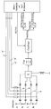
- a circuit diagram is also used to further explain the invention, with which the structure of a multiple receiver preferred according to the invention is shown schematically.
- a receiving and evaluating device preferred according to the invention can, for example, have a structure as shown in the single circuit diagram.
- Four receiving antennas A, B, C, N are provided for a vehicle, for example a car with four active wheels.
- a connecting line a, b, c, n leads from each antenna A, B, C, N to a summing point S.
- a diode acting as a switch or a transistor acting as a switch is inserted into each connecting line a, b, c, n.
- the receiver and evaluation device is provided with a microcontroller, which in turn is equipped with an input multiplexer circuit.
- a control line a ', b', c ', n' leads from the microcontroller to the associated connecting line a, b, c, n in order to control the respective switch and to put it either in the blocking state or in the forward state.
- the microcontroller can thus register which antenna is connected to the summing point at a given time.
- the summing point is connected to the receiver via a filter.
- the field strength that is present at the summing point at a specific point in time is also recorded.
- the field strength initially determined in analog form is converted into a digital field strength signal with the aid of an analog / digital converter and fed to the microcontroller for evaluation.
- the useful signals are fed to the microcontroller and evaluated via a data signal line.
Landscapes
- Engineering & Computer Science (AREA)
- Mechanical Engineering (AREA)
- Arrangements For Transmission Of Measured Signals (AREA)
- Measuring Fluid Pressure (AREA)
Applications Claiming Priority (2)
| Application Number | Priority Date | Filing Date | Title |
|---|---|---|---|
| DE19534616A DE19534616B4 (de) | 1995-09-18 | 1995-09-18 | Reifendruck-Überwachungseinrichtung |
| DE19534616 | 1995-09-18 |
Publications (2)
| Publication Number | Publication Date |
|---|---|
| EP0763437A1 true EP0763437A1 (fr) | 1997-03-19 |
| EP0763437B1 EP0763437B1 (fr) | 2001-07-11 |
Family
ID=7772497
Family Applications (1)
| Application Number | Title | Priority Date | Filing Date |
|---|---|---|---|
| EP96114843A Expired - Lifetime EP0763437B1 (fr) | 1995-09-18 | 1996-09-16 | Dispositif de surveillance de pneumatiques et récepteur à plusieures voies |
Country Status (6)
| Country | Link |
|---|---|
| US (1) | US6112585A (fr) |
| EP (1) | EP0763437B1 (fr) |
| AT (1) | ATE202978T1 (fr) |
| CA (1) | CA2185771A1 (fr) |
| DE (2) | DE19534616B4 (fr) |
| ES (1) | ES2161318T3 (fr) |
Cited By (10)
| Publication number | Priority date | Publication date | Assignee | Title |
|---|---|---|---|---|
| WO1998005518A1 (fr) * | 1996-08-07 | 1998-02-12 | Doduco Gmbh | Procede pour le traitement des signaux d'un systeme de surveillance de la pression des pneus |
| EP0861160B1 (fr) * | 1995-11-17 | 2000-04-05 | Beru AG | Procede d'attribution d'emetteurs a des antennes de receptions dans des systemes de surveillance de la pression des pneus |
| EP0937615A3 (fr) * | 1998-02-19 | 2000-08-30 | Siemens Aktiengesellschaft | Système de capteur et procédé pour surveiller/mesurer l'adhérence d'un pneu de véhicule avec la piste de roulage et autres données physiques du pneu |
| FR2798213A1 (fr) * | 1999-09-03 | 2001-03-09 | Sagem | Systeme de controle de la pression des pneumatiques d'un vehicule |
| EP1077144A3 (fr) * | 1999-08-17 | 2003-08-27 | Pacific Industrial Co., Ltd. | Système de surveillance de pression de pneumatique et méthode de surveillance |
| FR2866269A1 (fr) | 2004-01-07 | 2005-08-19 | Siemens Ag | Dispositif et procede pour determiner la position laterale de roues |
| DE10221593B4 (de) * | 2001-05-17 | 2005-12-22 | Lite-On Automotive Corp. | Code-Erkennungseinrichtung |
| EP1440824A3 (fr) * | 2003-01-22 | 2008-09-10 | Nissan Motor Company, Limited | Appareil et procédé de surveillance de la pression des pneumatiques |
| EP1859562A4 (fr) * | 2005-03-10 | 2011-06-15 | Delphi Tech Inc | Controle de la pression des pneus avec un systeme a antenne diversifiee et procede |
| CN104401191A (zh) * | 2014-11-28 | 2015-03-11 | 埃泰克汽车电子(芜湖)有限公司 | Tpms系统标定检测装置及其检测方法 |
Families Citing this family (52)
| Publication number | Priority date | Publication date | Assignee | Title |
|---|---|---|---|---|
| US6662642B2 (en) | 2000-09-08 | 2003-12-16 | Automotive Technologies International, Inc. | Vehicle wireless sensing and communication system |
| US6748797B2 (en) | 2000-09-08 | 2004-06-15 | Automotive Technologies International Inc. | Method and apparatus for monitoring tires |
| US7421321B2 (en) * | 1995-06-07 | 2008-09-02 | Automotive Technologies International, Inc. | System for obtaining vehicular information |
| US9443358B2 (en) | 1995-06-07 | 2016-09-13 | Automotive Vehicular Sciences LLC | Vehicle software upgrade techniques |
| DE19737945B4 (de) * | 1997-08-30 | 2004-05-19 | Continental Aktiengesellschaft | Verfahren zur Übertragung von Daten in einem Datenübertragungssystem und Datenübertragungssystem |
| DE19852454B4 (de) * | 1997-12-08 | 2005-11-10 | Fraunhofer-Gesellschaft zur Förderung der angewandten Forschung e.V. | Vorrichtung und Verfahren zum Verbessern einer Funkübertragung über eine Funkstrecke zwischen einem Sender und einem Empfänger |
| US10240935B2 (en) | 1998-10-22 | 2019-03-26 | American Vehicular Sciences Llc | Vehicle software upgrade techniques |
| US6710708B2 (en) * | 1999-02-05 | 2004-03-23 | Schrader-Bridgeport International, Inc. | Method and apparatus for a remote tire pressure monitoring system |
| DE19917210A1 (de) * | 1999-04-16 | 2000-10-26 | Hydac Technology Gmbh | Verfahren zur Überwachung des Gas-Vorfülldruckes bei Hydrospeichern |
| US6919799B2 (en) * | 1999-04-29 | 2005-07-19 | Bridgestone/Firestone North American Tire, Llc | Monitoring device and tire combination |
| DE19938431C2 (de) * | 1999-08-13 | 2001-09-27 | Continental Ag | System für ein Kraftfahrzeug mit einem Hochfrequenzsender und einem Hochfrequenzempfänger |
| US7467034B2 (en) * | 2002-11-04 | 2008-12-16 | Automotive Technologies International, Inc. | Tire monitoring techniques |
| US7161476B2 (en) | 2000-07-26 | 2007-01-09 | Bridgestone Firestone North American Tire, Llc | Electronic tire management system |
| US8266465B2 (en) | 2000-07-26 | 2012-09-11 | Bridgestone Americas Tire Operation, LLC | System for conserving battery life in a battery operated device |
| EP2272688B1 (fr) | 2000-07-26 | 2012-02-01 | Bridgestone Americas Tire Operations, LLC | Système électronique de gestion de pneus |
| US7911324B2 (en) * | 2001-02-16 | 2011-03-22 | Automotive Technologies International, Inc. | Method and system for obtaining information about RFID-equipped objects |
| DE10044365A1 (de) * | 2000-09-08 | 2002-04-04 | Hans Zapfe | Verfahren und Anordnung zum Überwachen von Starts und Landungen von Luftfahrzeugen |
| US6362731B1 (en) * | 2000-12-06 | 2002-03-26 | Eaton Corporation | Tire pressure monitor and location identification system and method |
| JP2002240521A (ja) | 2000-12-15 | 2002-08-28 | Pacific Ind Co Ltd | タイヤ状態監視装置 |
| JP3818632B2 (ja) * | 2000-12-27 | 2006-09-06 | 太平洋工業株式会社 | タイヤ状態監視装置及びタイヤ状態監視方法 |
| US6501372B2 (en) * | 2001-02-02 | 2002-12-31 | Trw Inc. | Tire condition sensor communication with unique sampling on vehicle-side diversity antenna array |
| US9084076B2 (en) | 2001-02-16 | 2015-07-14 | Intelligent Technologies International, Inc. | Techniques for obtaining information about objects |
| US6340930B1 (en) | 2001-03-07 | 2002-01-22 | Trw Inc. | System and method for monitoring a condition of a vehicle tire |
| FR2826731B1 (fr) * | 2001-06-28 | 2005-02-25 | Siemens Automotive Sa | Procede de localisation de capteurs montes chacun sur une roue de vehicule. |
| US6882270B2 (en) | 2001-10-29 | 2005-04-19 | Schrader Bridgeport International, Inc. | Determination of wheel sensor position using radio frequency detectors in an automotive remote tire monitor system |
| US7423532B2 (en) * | 2001-10-29 | 2008-09-09 | Schrader Bridgeport International, Inc. | Determination of wheel sensor position using a single radio frequency detector in an automotive remote tire monitor system |
| JP2003182328A (ja) * | 2001-12-21 | 2003-07-03 | Pacific Ind Co Ltd | タイヤ状態監視装置の送信機及びタイヤ状態監視装置 |
| JP4000891B2 (ja) * | 2002-04-12 | 2007-10-31 | トヨタ自動車株式会社 | タイヤ状態取得装置 |
| US7010968B2 (en) * | 2002-04-18 | 2006-03-14 | Schrader Bridgeport International, Inc. | Determination of wheel sensor position using a wireless solution |
| JP4041958B2 (ja) * | 2002-07-18 | 2008-02-06 | オムロン株式会社 | 空中線装置及びその空中線装置を含むタイヤ空気圧モニタリングシステム |
| JP3636184B2 (ja) * | 2002-07-31 | 2005-04-06 | 株式会社デンソー | タイヤ空気圧センサのid登録方法及びid登録システムと、タイヤ空気圧監視システム、タイヤ空気圧センサ及びスマート制御システム |
| DE10240159B3 (de) * | 2002-08-30 | 2004-07-15 | Nolex Ag | Reifenluftdruck-Kontrollvorrichtung |
| JP2004196007A (ja) * | 2002-12-16 | 2004-07-15 | Calsonic Kansei Corp | タイヤ空気圧検出装置 |
| DE10316074B4 (de) * | 2003-04-08 | 2006-01-26 | Global Dynamix Ag | Reifenluftdruck-Kontrollvorrichtung |
| DE10341785B4 (de) * | 2003-09-10 | 2006-04-27 | Global Dynamix Ag | Verfahren zur Zuordnung eines Radmoduls zu seiner Radposition und dafür geeignete Reifenluftdruck-Kontrollvorrichtung |
| JP2005119370A (ja) * | 2003-10-14 | 2005-05-12 | Pacific Ind Co Ltd | タイヤ状態監視装置の送信機 |
| DE10355897A1 (de) * | 2003-11-29 | 2005-06-30 | Daimlerchrysler Ag | Verfahren zum Aktivieren eines Betriebsmodus eines Fahrzeugsystems |
| EP1547879A3 (fr) * | 2003-12-25 | 2006-03-01 | Omron Corporation | Système de commande à distance pour véhicule automobile et système de surveillance de la pression des pneus |
| US7367227B2 (en) * | 2004-01-20 | 2008-05-06 | Schrader Bridgeport International | Determination of wheel sensor position using shock sensors and a wireless solution |
| US7362218B2 (en) * | 2004-01-20 | 2008-04-22 | Schrader Bridgeport International, Inc. | Motion detection using a shock sensor in a remote tire pressure monitoring system |
| DE102004018827B4 (de) * | 2004-04-19 | 2006-06-29 | Siemens Ag | Vorrichtung und Verfahren zur Ermittlung der Radposition von Rädern eines Radfahrzeuges |
| DE102004024388B4 (de) * | 2004-05-17 | 2006-07-06 | Siemens Ag | Vorrichtung und Verfahren zum Bestimmen einer Radposition |
| US7791461B2 (en) | 2004-06-16 | 2010-09-07 | Bridgestone Corporation | Tire management system with data demanding signal and tire status value transmitting at different cycles |
| DE102004032698A1 (de) * | 2004-07-06 | 2006-02-16 | Siemens Ag | Vorrichtung und Verfahren zum Bestimmen einer Radposition |
| DE102004034287A1 (de) * | 2004-07-15 | 2006-02-23 | Siemens Ag | Verfahren zur Lokalisierung wenigstens eines Rades eines Fahrzeuges |
| DE102004040790A1 (de) * | 2004-08-23 | 2006-03-16 | Global Dynamix Ag | Vorrichtung und Verfahren zur Reifenluftdruckkontrolle |
| DE102004042191B3 (de) * | 2004-08-31 | 2006-02-23 | Siemens Ag | Verfahren zur Lokalisierung wenigstens eines Rades eines Fahrzeuges |
| JP5019839B2 (ja) * | 2006-10-04 | 2012-09-05 | 株式会社ブリヂストン | タイヤ情報管理システム |
| TWI327534B (en) * | 2007-04-11 | 2010-07-21 | Kuender & Co Ltd | Tire identification system, tire pressure monitoring system using the same and method for tire identification |
| KR101365925B1 (ko) * | 2010-05-13 | 2014-02-25 | 주식회사 만도 | 타이어 압력 센서모듈 식별장치 |
| JP2013023868A (ja) * | 2011-07-19 | 2013-02-04 | Tokai Rika Co Ltd | 機能統合受信機 |
| US10216523B2 (en) | 2015-07-17 | 2019-02-26 | General Electric Company | Systems and methods for implementing control logic |
Citations (3)
| Publication number | Priority date | Publication date | Assignee | Title |
|---|---|---|---|---|
| FR2441502A1 (fr) * | 1978-11-20 | 1980-06-13 | Pappas Dennis | Dispositif d'alarme pour pression de pneu insuffisante |
| DE3104013A1 (de) * | 1980-02-07 | 1982-02-25 | Meisei Electric Co., Ltd., Tokyo | "system zum feststellen eines anomalen reifeninnendrucks" |
| DE4205911A1 (de) * | 1992-02-26 | 1993-09-02 | Uwatec Ag | Kontrollvorrichtung fuer den luftdruck von luftbereiften fahrzeugraedern |
Family Cites Families (15)
| Publication number | Priority date | Publication date | Assignee | Title |
|---|---|---|---|---|
| US4578992A (en) * | 1982-11-05 | 1986-04-01 | Philip E. Galasko | Detection of a low pressure condition of a vehicle tire |
| FR2577480B1 (fr) * | 1985-02-21 | 1987-12-11 | Labinal | Dispositif permettant la mesure de temperatures de freins et de pressions de pneumatiques sur des trains de roues de vehicules et notamment d'avions |
| US4978941A (en) * | 1988-07-11 | 1990-12-18 | Air Chex, Inc. | Low tire pressure detector |
| DE3930480A1 (de) * | 1989-09-12 | 1991-03-14 | Rainer Achterholt | Eine ein druckabnahmesignal erzeugende ventilkappe fuer einen luftreifen |
| DE3930479A1 (de) * | 1989-09-12 | 1991-03-14 | Rainer Achterholt | Ventil mit signalerzeugungseinrichtung fuer fahrzeugreifen |
| US5297424A (en) * | 1990-03-07 | 1994-03-29 | Monroe Auto Equipment Company | Telemetry system for tire pressure and temperature sensing |
| US5289160A (en) * | 1991-09-30 | 1994-02-22 | Fiorletta Carl A | Tire pressure monitoring system |
| DE4303591C2 (de) * | 1993-02-08 | 1996-02-22 | Alpha Beta Electronics Ag | Ventilkappe mit einer Einrichtung zur Erzeugung eines Druckanzeigesignals für einen mit einem Ventil ausgerüsteten Fahrzeugreifen |
| DE4303583C2 (de) * | 1993-02-08 | 1996-02-22 | Alpha Beta Electronics Ag | Ventil mit einer Einrichtung zur Erzeugung eines drahtlos übermittelbaren Druckabnahme-Anzeigesignals für Fahrzeugreifen |
| US5731754A (en) * | 1994-06-03 | 1998-03-24 | Computer Methods Corporation | Transponder and sensor apparatus for sensing and transmitting vehicle tire parameter data |
| US5581023A (en) * | 1994-10-31 | 1996-12-03 | Handfield; Michael | Pressure transducer for monitoring a pneumatic tire |
| DE19518806A1 (de) * | 1995-05-26 | 1996-11-28 | Duerrwaechter E Dr Doduco | Einrichtung an Fahrzeugen zum Überwachen des Luftdrucks in dessen Reifen |
| DE19618658A1 (de) * | 1996-05-09 | 1997-11-13 | Continental Ag | Luftdruckkontrollsystem |
| DE19632150B4 (de) * | 1996-08-09 | 2004-06-09 | Conti Temic Microelectronic Gmbh | Verfahren zur Kontrolle des Luftdrucks in den Reifen von Kraftfahrzeugrädern |
| DE69722336T2 (de) * | 1996-09-27 | 2003-11-27 | Motorola, Inc. | Reifendrucküberwachungssystem |
-
1995
- 1995-09-18 DE DE19534616A patent/DE19534616B4/de not_active Expired - Fee Related
-
1996
- 1996-09-05 US US08/708,579 patent/US6112585A/en not_active Expired - Fee Related
- 1996-09-16 DE DE59607259T patent/DE59607259D1/de not_active Expired - Fee Related
- 1996-09-16 EP EP96114843A patent/EP0763437B1/fr not_active Expired - Lifetime
- 1996-09-16 ES ES96114843T patent/ES2161318T3/es not_active Expired - Lifetime
- 1996-09-16 AT AT96114843T patent/ATE202978T1/de not_active IP Right Cessation
- 1996-09-17 CA CA002185771A patent/CA2185771A1/fr not_active Abandoned
Patent Citations (4)
| Publication number | Priority date | Publication date | Assignee | Title |
|---|---|---|---|---|
| FR2441502A1 (fr) * | 1978-11-20 | 1980-06-13 | Pappas Dennis | Dispositif d'alarme pour pression de pneu insuffisante |
| DE3104013A1 (de) * | 1980-02-07 | 1982-02-25 | Meisei Electric Co., Ltd., Tokyo | "system zum feststellen eines anomalen reifeninnendrucks" |
| DE4205911A1 (de) * | 1992-02-26 | 1993-09-02 | Uwatec Ag | Kontrollvorrichtung fuer den luftdruck von luftbereiften fahrzeugraedern |
| WO1993016891A1 (fr) * | 1992-02-26 | 1993-09-02 | Uwatec Ag | Dispositif de controle de la pression de gonflage de roues de vehicules equipees de pneus |
Cited By (12)
| Publication number | Priority date | Publication date | Assignee | Title |
|---|---|---|---|---|
| EP0861160B1 (fr) * | 1995-11-17 | 2000-04-05 | Beru AG | Procede d'attribution d'emetteurs a des antennes de receptions dans des systemes de surveillance de la pression des pneus |
| WO1998005518A1 (fr) * | 1996-08-07 | 1998-02-12 | Doduco Gmbh | Procede pour le traitement des signaux d'un systeme de surveillance de la pression des pneus |
| US6034597A (en) * | 1996-08-07 | 2000-03-07 | Ami Doduco Gmbh | Process for evaluating the signals from a tire pressure monitoring system |
| EP0937615A3 (fr) * | 1998-02-19 | 2000-08-30 | Siemens Aktiengesellschaft | Système de capteur et procédé pour surveiller/mesurer l'adhérence d'un pneu de véhicule avec la piste de roulage et autres données physiques du pneu |
| EP1077144A3 (fr) * | 1999-08-17 | 2003-08-27 | Pacific Industrial Co., Ltd. | Système de surveillance de pression de pneumatique et méthode de surveillance |
| FR2798213A1 (fr) * | 1999-09-03 | 2001-03-09 | Sagem | Systeme de controle de la pression des pneumatiques d'un vehicule |
| WO2001017805A1 (fr) * | 1999-09-03 | 2001-03-15 | Sagem Sa | Systeme de controle de la pression des pneumatiques d'un vehicule |
| DE10221593B4 (de) * | 2001-05-17 | 2005-12-22 | Lite-On Automotive Corp. | Code-Erkennungseinrichtung |
| EP1440824A3 (fr) * | 2003-01-22 | 2008-09-10 | Nissan Motor Company, Limited | Appareil et procédé de surveillance de la pression des pneumatiques |
| FR2866269A1 (fr) | 2004-01-07 | 2005-08-19 | Siemens Ag | Dispositif et procede pour determiner la position laterale de roues |
| EP1859562A4 (fr) * | 2005-03-10 | 2011-06-15 | Delphi Tech Inc | Controle de la pression des pneus avec un systeme a antenne diversifiee et procede |
| CN104401191A (zh) * | 2014-11-28 | 2015-03-11 | 埃泰克汽车电子(芜湖)有限公司 | Tpms系统标定检测装置及其检测方法 |
Also Published As
| Publication number | Publication date |
|---|---|
| ES2161318T3 (es) | 2001-12-01 |
| ATE202978T1 (de) | 2001-07-15 |
| DE19534616A1 (de) | 1997-03-20 |
| DE19534616B4 (de) | 2007-01-11 |
| DE59607259D1 (de) | 2001-08-16 |
| CA2185771A1 (fr) | 1997-03-19 |
| US6112585A (en) | 2000-09-05 |
| EP0763437B1 (fr) | 2001-07-11 |
Similar Documents
| Publication | Publication Date | Title |
|---|---|---|
| EP0763437A1 (fr) | Dispositif de surveillance de pneumatiques | |
| EP0915764B1 (fr) | Procede pour le traitement des signaux d'un systeme de surveillance de la pression des pneus | |
| DE10014076B4 (de) | Reifenluftdruck-Anzeigevorrichtung | |
| DE19720123C2 (de) | Verfahren und Einrichtung zum Übertragen von Fernwirkbefehlen und von Meßdaten an einen oder mehrere Aktuatoren bzw. Überwachungsgeräte in einem Automobil | |
| EP1052119B1 (fr) | Procédé pour déterminer la position des roues dans un système de surveillance de pression des pneumatiques d'un véhicule | |
| EP0828621B1 (fr) | Dispositif monte sur des vehicules pour controler la pression des pneus | |
| EP1135268B1 (fr) | Systeme de transmission a un appareil d'evaluation place dans un vehicule des signaux d'un dispositif de surveillance de la pression des pneus sur les roues du vehicule | |
| DE10203624B4 (de) | System und Verfahren für eine gemeinsame Überwachung des Reifendrucks eines Fahrzeugs, den schlüssellosen Fernzugang und die Immobilisierung des Fahrzeugs | |
| DE3820454A1 (de) | Flaechen-nachrichtenuebertragungs-system | |
| DE10014949A1 (de) | Einrichtung an Fahrzeugen mit Rädern, die Luftreifen haben, zur Verwendung in einem Reifendrucküberwachungssystem | |
| EP0944485B1 (fr) | Procede permattant de detecter a qual endroit d'un vehicule equipe d'une installation de controle de la pression des pneus se trouve une roue donnee | |
| EP0567905B1 (fr) | Système de transmission de données bidirectionelle entre une balise et un véhicule | |
| DE102005059715B4 (de) | Verfahren und Vorrichtung zur Ortung der Position von Rädern eines Kraftfahrzeugs | |
| EP1550239B1 (fr) | Procede pour transmettre un protocole de donnees sur une liaison radio hf | |
| DE102007044395B4 (de) | Verfahren und Vorrichtung zur Zuordnung eines ersten Fahrzeugs zu einem zweiten Fahrzeug | |
| DE19734749C2 (de) | Vorrichtung zur Versorgung einer elektrischen Einrichtung in Kraftfahrzeugen | |
| EP1807270B1 (fr) | Systeme de verification de pression de pneumatiques pour vehicule automobile | |
| EP0609694B1 (fr) | Emetteur-récepteur et procédé d'émission et de réception d'informations numériques | |
| DE10152337A1 (de) | Verfahren und System zur Ermittlung von Radpositionen | |
| DE10229465B4 (de) | Anordnung zur Überwachung wenigstens eines Parameters für mehrere Fahrzeugräder | |
| DE10221593B4 (de) | Code-Erkennungseinrichtung | |
| EP0767554A2 (fr) | Récepteur avec système RDS comportant un récepteur supplémentaire | |
| EP0596240B1 (fr) | Dispositif pour la transmission de valeurs de mesure par une liaison vertio à haute fréquence | |
| DE102016203047B4 (de) | Verfahren und Vorrichtungen für insbesondere ein Kraftfahr-Zugzugangs- und/oder -Start-System | |
| DE19825702A1 (de) | Radar-Abstandssensorik |
Legal Events
| Date | Code | Title | Description |
|---|---|---|---|
| PUAI | Public reference made under article 153(3) epc to a published international application that has entered the european phase |
Free format text: ORIGINAL CODE: 0009012 |
|
| AK | Designated contracting states |
Kind code of ref document: A1 Designated state(s): AT BE CH DE ES FR GB IT LI SE |
|
| 17P | Request for examination filed |
Effective date: 19970428 |
|
| 17Q | First examination report despatched |
Effective date: 20000125 |
|
| RTI1 | Title (correction) |
Free format text: TYRE-PRESSURE SURVEILLANCE DEVICE AND MULTIPATH RECEIVER THEREFORE |
|
| GRAG | Despatch of communication of intention to grant |
Free format text: ORIGINAL CODE: EPIDOS AGRA |
|
| GRAG | Despatch of communication of intention to grant |
Free format text: ORIGINAL CODE: EPIDOS AGRA |
|
| GRAH | Despatch of communication of intention to grant a patent |
Free format text: ORIGINAL CODE: EPIDOS IGRA |
|
| GRAH | Despatch of communication of intention to grant a patent |
Free format text: ORIGINAL CODE: EPIDOS IGRA |
|
| GRAA | (expected) grant |
Free format text: ORIGINAL CODE: 0009210 |
|
| AK | Designated contracting states |
Kind code of ref document: B1 Designated state(s): AT BE CH DE ES FR GB IT LI SE |
|
| REF | Corresponds to: |
Ref document number: 202978 Country of ref document: AT Date of ref document: 20010715 Kind code of ref document: T |
|
| REG | Reference to a national code |
Ref country code: CH Ref legal event code: EP |
|
| REF | Corresponds to: |
Ref document number: 59607259 Country of ref document: DE Date of ref document: 20010816 |
|
| ITF | It: translation for a ep patent filed | ||
| GBT | Gb: translation of ep patent filed (gb section 77(6)(a)/1977) |
Effective date: 20010925 |
|
| REG | Reference to a national code |
Ref country code: CH Ref legal event code: NV Representative=s name: LUCHS & PARTNER PATENTANWAELTE |
|
| REG | Reference to a national code |
Ref country code: ES Ref legal event code: FG2A Ref document number: 2161318 Country of ref document: ES Kind code of ref document: T3 |
|
| ET | Fr: translation filed | ||
| REG | Reference to a national code |
Ref country code: GB Ref legal event code: IF02 |
|
| PLBE | No opposition filed within time limit |
Free format text: ORIGINAL CODE: 0009261 |
|
| STAA | Information on the status of an ep patent application or granted ep patent |
Free format text: STATUS: NO OPPOSITION FILED WITHIN TIME LIMIT |
|
| 26N | No opposition filed | ||
| PGFP | Annual fee paid to national office [announced via postgrant information from national office to epo] |
Ref country code: DE Payment date: 20050822 Year of fee payment: 10 |
|
| PGFP | Annual fee paid to national office [announced via postgrant information from national office to epo] |
Ref country code: GB Payment date: 20050902 Year of fee payment: 10 |
|
| PGFP | Annual fee paid to national office [announced via postgrant information from national office to epo] |
Ref country code: FR Payment date: 20050920 Year of fee payment: 10 |
|
| PGFP | Annual fee paid to national office [announced via postgrant information from national office to epo] |
Ref country code: BE Payment date: 20050922 Year of fee payment: 10 Ref country code: AT Payment date: 20050922 Year of fee payment: 10 |
|
| PGFP | Annual fee paid to national office [announced via postgrant information from national office to epo] |
Ref country code: SE Payment date: 20050923 Year of fee payment: 10 Ref country code: CH Payment date: 20050923 Year of fee payment: 10 |
|
| PGFP | Annual fee paid to national office [announced via postgrant information from national office to epo] |
Ref country code: ES Payment date: 20050927 Year of fee payment: 10 |
|
| PG25 | Lapsed in a contracting state [announced via postgrant information from national office to epo] |
Ref country code: AT Free format text: LAPSE BECAUSE OF NON-PAYMENT OF DUE FEES Effective date: 20060916 |
|
| PG25 | Lapsed in a contracting state [announced via postgrant information from national office to epo] |
Ref country code: SE Free format text: LAPSE BECAUSE OF NON-PAYMENT OF DUE FEES Effective date: 20060917 |
|
| PG25 | Lapsed in a contracting state [announced via postgrant information from national office to epo] |
Ref country code: LI Free format text: LAPSE BECAUSE OF NON-PAYMENT OF DUE FEES Effective date: 20060930 Ref country code: CH Free format text: LAPSE BECAUSE OF NON-PAYMENT OF DUE FEES Effective date: 20060930 Ref country code: BE Free format text: LAPSE BECAUSE OF NON-PAYMENT OF DUE FEES Effective date: 20060930 |
|
| PGFP | Annual fee paid to national office [announced via postgrant information from national office to epo] |
Ref country code: IT Payment date: 20060930 Year of fee payment: 11 |
|
| PG25 | Lapsed in a contracting state [announced via postgrant information from national office to epo] |
Ref country code: DE Free format text: LAPSE BECAUSE OF NON-PAYMENT OF DUE FEES Effective date: 20070403 |
|
| REG | Reference to a national code |
Ref country code: CH Ref legal event code: PL |
|
| EUG | Se: european patent has lapsed | ||
| GBPC | Gb: european patent ceased through non-payment of renewal fee |
Effective date: 20060916 |
|
| REG | Reference to a national code |
Ref country code: FR Ref legal event code: ST Effective date: 20070531 |
|
| PG25 | Lapsed in a contracting state [announced via postgrant information from national office to epo] |
Ref country code: GB Free format text: LAPSE BECAUSE OF NON-PAYMENT OF DUE FEES Effective date: 20060916 |
|
| REG | Reference to a national code |
Ref country code: ES Ref legal event code: FD2A Effective date: 20060918 |
|
| BERE | Be: lapsed |
Owner name: *ALPHA-BETA ELECTRONICS A.G. Effective date: 20060930 |
|
| PG25 | Lapsed in a contracting state [announced via postgrant information from national office to epo] |
Ref country code: ES Free format text: LAPSE BECAUSE OF NON-PAYMENT OF DUE FEES Effective date: 20060918 |
|
| PG25 | Lapsed in a contracting state [announced via postgrant information from national office to epo] |
Ref country code: FR Free format text: LAPSE BECAUSE OF NON-PAYMENT OF DUE FEES Effective date: 20061002 |
|
| PG25 | Lapsed in a contracting state [announced via postgrant information from national office to epo] |
Ref country code: IT Free format text: LAPSE BECAUSE OF NON-PAYMENT OF DUE FEES Effective date: 20070916 |