EP0763625B1 - Vorrichtung für eine Papiermaschine zur Förderung von Flüssigkeit von einem ersten Niveau auf ein zweites, höheres Niveau - Google Patents
Vorrichtung für eine Papiermaschine zur Förderung von Flüssigkeit von einem ersten Niveau auf ein zweites, höheres Niveau Download PDFInfo
- Publication number
- EP0763625B1 EP0763625B1 EP96113173A EP96113173A EP0763625B1 EP 0763625 B1 EP0763625 B1 EP 0763625B1 EP 96113173 A EP96113173 A EP 96113173A EP 96113173 A EP96113173 A EP 96113173A EP 0763625 B1 EP0763625 B1 EP 0763625B1
- Authority
- EP
- European Patent Office
- Prior art keywords
- line
- liquid
- level
- chamber
- gas
- Prior art date
- Legal status (The legal status is an assumption and is not a legal conclusion. Google has not performed a legal analysis and makes no representation as to the accuracy of the status listed.)
- Expired - Lifetime
Links
- 239000012530 fluid Substances 0.000 title claims abstract description 19
- 239000007788 liquid Substances 0.000 claims description 59
- 238000000034 method Methods 0.000 claims description 6
- 238000013022 venting Methods 0.000 claims 1
- 230000010349 pulsation Effects 0.000 abstract description 5
- 239000000314 lubricant Substances 0.000 description 9
- 230000033228 biological regulation Effects 0.000 description 5
- 230000000694 effects Effects 0.000 description 3
- 230000001050 lubricating effect Effects 0.000 description 3
- 238000012986 modification Methods 0.000 description 3
- 230000004048 modification Effects 0.000 description 3
- 230000007423 decrease Effects 0.000 description 2
- 238000001035 drying Methods 0.000 description 2
- 238000005187 foaming Methods 0.000 description 2
- 230000000750 progressive effect Effects 0.000 description 2
- 230000001052 transient effect Effects 0.000 description 2
- 238000006073 displacement reaction Methods 0.000 description 1
- 230000005484 gravity Effects 0.000 description 1
- 239000004519 grease Substances 0.000 description 1
- 238000007726 management method Methods 0.000 description 1
- 238000004519 manufacturing process Methods 0.000 description 1
- 230000036316 preload Effects 0.000 description 1
- 230000001737 promoting effect Effects 0.000 description 1
- 230000001105 regulatory effect Effects 0.000 description 1
- 238000007789 sealing Methods 0.000 description 1
- 238000009423 ventilation Methods 0.000 description 1
Images

Classifications
-
- D—TEXTILES; PAPER
- D21—PAPER-MAKING; PRODUCTION OF CELLULOSE
- D21F—PAPER-MAKING MACHINES; METHODS OF PRODUCING PAPER THEREON
- D21F3/00—Press section of machines for making continuous webs of paper
- D21F3/02—Wet presses
- D21F3/0209—Wet presses with extended press nip
- D21F3/0218—Shoe presses
- D21F3/0227—Belts or sleeves therefor
- D21F3/0245—Means for fixing the sleeve to the roller end
-
- D—TEXTILES; PAPER
- D21—PAPER-MAKING; PRODUCTION OF CELLULOSE
- D21F—PAPER-MAKING MACHINES; METHODS OF PRODUCING PAPER THEREON
- D21F5/00—Dryer section of machines for making continuous webs of paper
- D21F5/02—Drying on cylinders
- D21F5/10—Removing condensate from the interior of the cylinders
-
- D—TEXTILES; PAPER
- D21—PAPER-MAKING; PRODUCTION OF CELLULOSE
- D21G—CALENDERS; ACCESSORIES FOR PAPER-MAKING MACHINES
- D21G1/00—Calenders; Smoothing apparatus
- D21G1/02—Rolls; Their bearings
- D21G1/0206—Controlled deflection rolls
- D21G1/0213—Controlled deflection rolls with deflection compensation means acting between the roller shell and its supporting member
- D21G1/022—Controlled deflection rolls with deflection compensation means acting between the roller shell and its supporting member the means using fluid pressure
-
- F—MECHANICAL ENGINEERING; LIGHTING; HEATING; WEAPONS; BLASTING
- F16—ENGINEERING ELEMENTS AND UNITS; GENERAL MEASURES FOR PRODUCING AND MAINTAINING EFFECTIVE FUNCTIONING OF MACHINES OR INSTALLATIONS; THERMAL INSULATION IN GENERAL
- F16C—SHAFTS; FLEXIBLE SHAFTS; ELEMENTS OR CRANKSHAFT MECHANISMS; ROTARY BODIES OTHER THAN GEARING ELEMENTS; BEARINGS
- F16C13/00—Rolls, drums, discs, or the like; Bearings or mountings therefor
- F16C13/02—Bearings
- F16C13/022—Bearings supporting a hollow roll mantle rotating with respect to a yoke or axle
- F16C13/024—Bearings supporting a hollow roll mantle rotating with respect to a yoke or axle adjustable for positioning, e.g. radial movable bearings for controlling the deflection along the length of the roll mantle
- F16C13/026—Bearings supporting a hollow roll mantle rotating with respect to a yoke or axle adjustable for positioning, e.g. radial movable bearings for controlling the deflection along the length of the roll mantle by fluid pressure
Definitions
- the invention relates to a device for a paper machine to convey liquid from a first level in one first room through a pipe into a second room on one second, higher level under the effect of a difference of Gas pressures above the liquid in the first room and in the second Space, especially for the suction of liquid from a roller.
- Such a device and such a method are known from DE 44 01 582 A1.
- the liquid is conveyed from the first level to one second, higher level using a gas pressure difference between the first room (inlet room) and the second room (Discharge area).
- a gas pressure difference between the first room (inlet room) and the second room (Discharge area) is in a suction line for suction of the liquid Gas separator arranged from which the liquid by means of further management to the second level becomes.
- US-A-4 205 457 is a device for the removal of condensate according to the siphon principle from the Disclosed inside a drying cylinder to the outside.
- a throttle valve on the siphon depending on the the condensate gas pressure controlled so that at increased gas pressure or increased pressure drop at the siphon open cross-sectional area of the throttle slide enlarged becomes.
- the Gas pressure used within the cylinder so that the known device in any way to solve the above problem described is suitable.
- the invention is therefore based on the object of a device and a method for a paper machine for conveying of liquid from a first level in a first room through a line to a second, higher level with the help to create a gas pressure difference, with which a constant promotion the liquid is guaranteed, stable flow conditions prevail and production with a low gas content is achieved that is largely free of pulsations.
- a throttle valve for regulation the fluid flow through the line is provided, which in Controlled depending on the gas flow through the line is that the fluid flow through as the gas flow increases the line is throttled.
- the object of the invention is also regarding the method solved in that in the method according to the introduction mentioned type the flow of the fluid through the line is throttled when the amount of gas flowing through the line increases.
- a particular advantage of the invention is that a relatively small amount of gas is required to promote to bring the liquid to a higher level.
- the mass ratio from delivered liquid to used gas volume can advantageously be in a range between about 1:10 to about 10: 1, with a ratio of about 1: 1 is sought.
- a sensor is arranged, which the gas flow rate detected.
- the throttle valve in the line from the first room to second room can be controlled via an actuator such that when increasing the gas flow rate, the fluid flow through the Line is throttled.
- the sensor too can capture other manipulated variables to throttle the Throttle valve when increasing the gas content in the discharged To achieve fluid. For example, instead of the gas flow rate even in the simplest case, only the pressure difference between the first room and the second room. Also are numerous designs of the actuator are conceivable.
- the Conduction in a buoyancy body in the second room at least partially immersed in the liquid in the second room and over whose thrust is controlled by the throttle valve.
- the buoyancy body as a bell-shaped body open at the bottom, which has a vent nozzle at its upper end.
- this includes Throttle valve a sliding sleeve that can be moved on the line, via the one outlet opening of the line at least partially is lockable.
- the sliding sleeve can be moved vertically on the line arranged and rigidly connected to the buoyancy body.
- the line is formed as a tube that has at least one inlet opening the first level and an exit opening on the second Level, the throttle valve one in the tube guided piston, through which the inlet opening at least is partially closable, and with the piston at the bottom End of a piston rod is attached to an upper end of the tube is slidably guided, and that at its upper End is rigidly connected to the buoyancy body.
- the buoyancy of the buoyancy body becomes used to flow through with increased gas flow to reduce the throttle valve.
- the control is carried out on Inlet of the line, namely by the at least one inlet opening reduced when the lift is increased by the piston becomes.
- the buoyancy body with the piston over the Piston rod rigidly connected.
- the gas flow takes through the line and thus increases the lift of the Buoyancy body, so the at least one inlet opening reduced in size via the piston, which throttles the fluid flow becomes.
- Buoyancy body biased by a spring such that the Throttle point is largely open at low buoyancy.
- an upper one and a lower stop to limit the upper and the provided lower end position of the buoyancy body.
- the second mentioned version of the throttle valve used as a lower stop for the piston Serve plug that closes the lower end of the line, if the piston is penetrated by a pressure equalization opening is.
- An external stop can be used as the upper stop serve for the buoyancy body or a projection on the Piston rod, with which this at its guide at the top of the vertical pipe.
- a roller which has a plurality of lines for Suction of liquid from the inside of the roller is provided, is preferably any line with an inventive Suction device coupled.
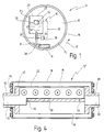
- Fig. 1 shows a shoe press roll for a paper machine in highly simplified representation, the total with the digit 12 is designated.
- the shoe press roll 12 comprises in a known manner Way a supporting body mounted on its two outer pins (not shown) and a press shoe 14, via the one closed press jacket 16 on a hydrodynamic lubricating film circulates.
- the press shoe 14, as shown in FIG. 2 in more detail is seen, via pressure elements 60 hydrostatically against one Counter roll (not shown) pressed to one by the Press nip led together with at least one felt web aqueous To drain paper web.
- the press jacket 16 is sealed on the end faces of the shoe press roll 12 by means of side windows 64 (see FIG. 3), so that a first chamber 18 or inlet chamber enclosed by the press jacket 16 results, within which a gas pressure p 1 prevails.
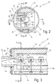
- lubricant In order to ensure a sufficient hydrodynamic lubricating film for the press jacket 16 even with high press forces in the press nip, lubricant must be continuously supplied in the area of the press shoe 14 via a plurality of openings, while the excess lubricant is shown in the area on the left in FIG. 1 collects in front of the press shoe if the shoe press roll 12 rotates counterclockwise, as indicated by arrow 17.
- the excess lubricant must be constantly sucked off and is conveyed via a line 32 into an overlying second space 20, which is enclosed by a container 22.
- the second space 20 there is a gas pressure p 2 above the liquid level, which is indicated by the number 36, which is lower than the gas pressure p 1 above the liquid level 34 in the first space 18.
- a sensor is arranged within the second space 20, which is indicated only schematically by the number 24.
- the sensor 24 detects the gas flow rate of the gas flowing into the second space via the line 32 or the amount of gas discharged to the outside from the second space 20.
- a throttle valve 28 which can be controlled with the aid of the signal picked up by sensor 24 via a control line 30 with the aid of an actuator 26.
- the throttle valve 28 is controlled via the actuator 26 in dependence on the signal picked up by the sensor 24 such that the flow rate through the throttle valve 28 is reduced when the gas flow rate detected by the sensor 24 increases. Conversely, the throttle valve 28 opens when the amount of gas delivered drops below a set value. This ensures that the first liquid level 34 in front of the press shoe 14 is kept at the lowest level and that the differential pressure p 1 -p 2 cannot collapse even with several parallel lines 32. A steady, largely laminar suction of excess lubricant through line 32 is thus established, which is free from pulsations and the like.
- the mass ratio lies between the funded Liquid and the pumped gas in a range of about 1:10 to 10: 1, where usually a value in the range of about 1: 1 sets so that very little gas to promote the liquid to a higher level is needed.
- the support body 42 is shown schematically, its cross section has the basic shape of a double T-beam, the top and lower end for guiding the circumferential press jacket 16 in sections is rounded.
- the support body 42 includes one Mittelsteg 58, which connects the upper and lower half.
- the Support body 42 ends at both ends of the press roll 12 'in pins 62, 88 (see FIG. 4), which are in ball bushings on the machine frame can be stored (not shown).
- Pins 62, 88 of the support body 42 are each of coaxial openings 54 and 90 enforced.
- the side windows are also on the pins 62 and 88, respectively 64 rotatably supported by means of pivot bearings 66, via the the first space 18 enclosed by the press jacket 16 to the End faces is sealed.
- the container 22 In a cavity to the left of the central web 58 of the support body 42, the container 22 is provided (FIG. 2), which is opposite the right, driver-side pin 88 of the shoe press roll 12 ' is sealed and sealing on the support body 42 on the engine side connected.
- driver-side pin 88 of the shoe press roll 12 ' Used to discharge the lubricant a recess 56 at the end of the central web 58 through the space 20 is connected to the bore 54 of the pin 62 (Fig. 3).
- the lubricant can be supplied by a not shown Feed line through one of the two pin bores 54 or 90 done.
- the line 32 has a lower end 38 with a Inlet nozzle, not shown, in the liquid dips in front of the press shoe 14.
- the line 32 is vertical Tube formed and has 40 in the region of its upper end one or more outlet openings 48 in the form of elongated Slits on.
- the line 32 is in the region of its upper end 40 by one Surrounding buoyancy body 46, the bell-shaped as open at the bottom or pot-shaped body is formed and over a Linkage 50 is rigidly connected to the sliding sleeve 52.
- a vent nozzle 44 At the upper end of the buoyancy body 46 is a vent nozzle 44 provided a slow gas escape from the from the float 46 enclosed space up into the second room 20 allows.
- the z. B. can be maintained by blowers, liquid discharged upwards, which can exit through the outlet openings 48, provided that the sliding sleeve 52 is due to the weight of the buoyancy body 46 in its lower end position or in the vicinity thereof, so that the outlet openings 48 are released. If the amount of gas entrained by the line 32 now rises to such an extent that it can no longer escape upward from the buoyancy body 46 via the vent nozzle 44, a gas bubble gradually accumulates within the buoyancy body 46, through which the buoyancy body 46 unites one Buoyancy is experienced since this is at least partially immersed in the liquid in the second space 20.
- the buoyancy body 46 moves with the sliding sleeve 52 upwards and thus begins to close the outlet openings 48, so that the flow through the line 32 is reduced. This simultaneously decreases the amount of gas conveyed through line 32, so that the gas bubble in the buoyancy body 46 can gradually be emptied again via the vent nozzle 44, so that the buoyancy subsides and the sliding sleeve 52 is moved down again.
- the height of the liquid level 36 within the second space 20 is preferably kept constant, for which purpose, for example, an overflow plate 51 can be provided according to FIG. 3.
- the amount of Liquid level 36 in the second room is not critical as long as it is ensured that the buoyancy body 46 at least partially immersed in the liquid. The functionality is thus ensured with a liquid level 36, in which the buoyancy body 46 completely into the liquid immersed as well at a liquid level 36 'that is below the level of the liquid level 36 but the buoyancy body 46 still partially in the liquid immersed.
- the throttle point 28 with the buoyancy body 46 shown enlarged.
- an upper stop 68 and a lower stop 70 on the line 32 to limit the displacement of the sliding sleeve 50 evident.
- the buoyancy body 46 can also expand a little downwards, for example a slightly different one Setting the control characteristic. Otherwise corresponds to 5 according to FIG. 2 to 4 explained execution
- the connecting line 32 ' is designed as a vertical tube, that at its lower end by a plug 84 and at its upper end is closed by a ring 86.
- Above the Plugs 84 are several in the side wall of tube 32 ' Entry openings 76 are provided while in the area of the upper
- a plurality of outlet openings 48 ' is provided at the end of the tube 32' are.
- a piston 74 is displaceable within the tube 32 ' out, through which the inlet openings 76 can be closed.
- the piston is rigidly connected to a piston rod 72 which protrudes upward from the tube 32 'at its upper end and is slidably guided on the ring 86.
- the top end the piston rod 72 is with a collar 80 of the buoyancy body 46 'rigidly connected, which is otherwise based entirely on the previous one 1 to 5 described buoyancy body 46 corresponds.
- the piston 74 is in a pressure compensation opening 78 in Vertical direction penetrates so that the piston 74 after can move down to the plug 84, which acts as a stop serves for the lower end position.
- the upper end position of the Piston 74 is delimited by a stop 102 on the container 22 is attached (not shown).
- the piston is 74 within the line 32 'designed as a vertical tube can be moved up and down by a certain amount, the upwards by a stop of the collar 80 of the buoyancy body 46 'is limited to the stop 102 and down by a Stop the piston 74 on the plug 84 at the lower end of the Line 32 '.
- Is between the collar 80 and the stop 102 additionally arranged a coil spring 82 through which the Buoyancy body 46 'is applied downwards.
- the piston 74 acts in conjunction with the inlet openings 76 as a throttle point 28 ', the flow through the position of the piston with respect to the inlet openings 76 is determined becomes. A movement occurs through the pressure compensation opening 78 of the piston 74 to the lower end position to the stop on Plug 84 allows.
- the spring 82 allows a more sensitive adjustment of the Achieve control characteristics of the throttle valve 28 'because the Restoring force not only by the weight of the Buoyancy body or the piston rod and the piston due is, but is determined by the spring force. It leaves through the selection of the spring characteristic of the spring 82 a sensitive coordination and also a progressive control characteristic of the throttle valve 28 '.
- FIG. 7 shows a further modification of the embodiment according to FIG. 5, in which the upper end of the line 32 is not is simply closed, but by a pressure relief valve 94 is closed, which is exceeded when a predetermined Differential pressure between the inside of the line 32 and the second room 20 opens.
- This safety function is only schematically indicated by a spring 96, the pins 98, 100 is attached to the wall of line 32 and that Pressure valve 94 biased to close.
Landscapes
- Physics & Mathematics (AREA)
- Fluid Mechanics (AREA)
- Engineering & Computer Science (AREA)
- General Engineering & Computer Science (AREA)
- Mechanical Engineering (AREA)
- Paper (AREA)
- Jet Pumps And Other Pumps (AREA)
Description
- Fig. 1
- einen Querschnitt einer Schuhpreßwalze in stark vereinfachter Darstellung, bei dem lediglich die erfindungsgemäße Vorrichtung, der Preßschuh und der Preßmantel dargestellt sind;
- Fig. 2
- einen Querschnitt einer Schuhpreßwalze mit einer alternativen Ausführung der erfindungsgemäßen Vorrichtung;
- Fig. 3
- einen Schnitt durch die Schuhpreßwalze gemäß Fig. 2 längs der Linie III-III;
- Fig. 4
- einen Schnitt durch die Schuhpreßwalze gemäß Fig. 2 längs der Linie IV-IV (in verkleinertem Maßstab) ;
- Fig. 5
- einen Schnitt durch das Drosselventil gemäß Fig. 2 in vergrößerter Darstellung im Bereich des oberen Endes der Leitung;
- Fig. 6
- eine Abwandlung von der Ausführung gemäß Fig. 5 und
- Fig. 7
- einen Längsschnitt durch die Leitung im Bereich der Austrittsöffnungen in vergrößerter Darstellung, wobei zusätzlich ein Überdruckventil vorgesehen ist.
Claims (14)
- Vorrichtung für eine Papiermaschine zur Förderung von Flüssigkeit von einem ersten Niveau in einem ersten Raum (18) durch eine Leitung (32) in einen zweiten Raum (20) auf ein zweites, höheres Niveau unter Wirkung einer Differenz der Gasdrücke (p1, p2) über der Flüssigkeit im ersten Raum (18) und im zweiten Raum (20), insbesondere zur Absaugung von Flüssigkeit von einer Walze (12), dadurch gekennzeichnet, daß ein Drosselventil (28; 28') zur Regulierung des Fluidstromes durch die Leitung (32; 32') vorgesehen ist, das in Abhängigkeit vom Gasfluß durch die Leitung (32; 32') derart gesteuert ist, daß der Fluidstrom bei Erhöhung des Gasdurchflusses durch die Leitung (32; 32') gedrosselt wird.
- Vorrichtung nach Anspruch 1, dadurch gekennzeichnet, daß die Leitung (32; 32') unmittelbar in den zweiten Raum (20) mündet, und daß ein Sensor (24) die Gasdurchflußmenge in oder aus dem zweiten Raum (20) erfaßt und mit dem Drosselventil (28; 28') über ein Stellglied (26) gekoppelt ist.
- Vorrichtung nach Anspruch 1 oder 2, dadurch gekennzeichnet, daß die Leitung (32; 32') in einen Auftriebskörper (46; 46') im zweiten Raum (20) mündet, der zumindest teilweise in die Flüssigkeit im zweiten Raum (20) eintaucht und über dessen Auftriebskraft das Drosselventil (28; 28') gesteuert wird.
- Vorrichtung nach Anspruch 3, dadurch gekennzeichnet, daß eine Einrichtung (51) zur Konstanthaltung der Höhe des Flüssigkeitsspiegels (36; 36') im zweiten Raum (20) vorgesehen ist.
- Vorrichtung nach Anspruch 3 oder 4, dadurch gekennzeichnet, daß der Auftriebskörper (46; 46') als nach unten offener, glockenartiger Körper ausgebildet ist, der eine Entlüftungsdüse (44) an seinem oberen Ende aufweist.
- Vorrichtung nach einem oder mehreren der vorhergehenden Ansprüche, dadurch gekennzeichnet, daß das Drosselventil (28) eine auf der Leitung (32) verschiebliche Schiebehülse (52) umfaßt, über die eine Austrittsöffnung (48) der Leitung (32) zumindest teilweise verschließbar ist.
- Vorrichtung nach Anspruch 6, dadurch gekennzeichnet, daß die Schiebehülse (52) auf der Leitung (32) vertikal verschieblich angeordnet ist und mit dem Auftriebskörper (46) starr verbunden ist.
- Vorrichtung nach Anspruch 3, 4 oder 5, dadurch gekennzeichnet, daß die Leitung (32') als Rohr ausgebildet ist, das zumindest eine Eintrittsöffnung (76) auf dem ersten Niveau und eine Austrittsöffnung (48') auf dem zweiten Niveau aufweist, daß die Drosselstelle (28') einen in dem Rohr geführten Kolben (74) umfaßt, durch den die Eintrittsöffnung (76) zumindest teilweise verschließbar ist, und daß der Kolben (74) am unteren Ende einer Kolbenstange (72) befestigt ist, die an einem oberen Ende des Rohrs verschieblich geführt ist, und die an ihrem oberen Ende mit dem Auftriebskörper (46') starr verbunden ist.
- Vorrichtung nach einem oder mehreren der Ansprüche 3 bis 8, dadurch gekennzeichnet, daß der Auftriebskörper (46, 46') durch eine Feder (82) derart vorgespannt ist, daß die Drosselstelle (28, 28') bei geringem Auftrieb weitgehend geöffnet ist.
- Vorrichtung nach einem oder mehreren der Ansprüche 3 bis 9, dadurch gekennzeichnet, daß ein oberer und ein unterer Anschlag (68, 70; 86, 84) zur Begrenzung der oberen und der unteren Endstellung des Auftriebskörpers (46; 46') vorgesehen ist.
- Vorrichtung nach einem oder mehreren der vorhergehenden Ansprüche, dadurch gekennzeichnet, daß die Leitung (32) unter Umgehung der Drosselstelle (28') über ein Überdruckventil (94), das bei Überschreitung eines vorgegebenen Druckes öffnet, unmittelbar mit dem zweiten Raum (20) verbunden ist.
- Walze für eine Papiermaschine, umfassend eine Mehrzahl von Leitungen (32; 32') zur Absaugung von Flüssigkeit aus der Walze, dadurch gekennzeichnet, daß jede Leitung (32; 32') eine Vorrichtung gemäß einem der Ansprüche 1 bis 10 umfaßt.
- Verfahren zur Förderung einer Flüssigkeit von einem ersten Niveau durch eine Leitung (32; 32') auf ein zweites, höheres Niveau unter Wirkung einer Differenz der Gasdrücke (p1, p2) über der Flüssigkeit auf dem ersten Niveau und auf dem zweiten Niveau, dadurch gekennzeichnet, daß die Strömung des Fluids durch die Leitung (32; 32') gedrosselt wird, wenn die durch die Leitung (32; 32') strömende Gasmenge ansteigt.
- Verfahren nach Anspruch 13, bei dem das Verhältnis zwischen der Masse der geförderten Flüssigkeit und der zur Förderung verbrauchten Gasmenge im Bereich von etwa 1:10 bis etwa 10:1 liegt, vorzugsweise im Bereich von etwa 1:1.
Applications Claiming Priority (2)
| Application Number | Priority Date | Filing Date | Title |
|---|---|---|---|
| DE19534571 | 1995-09-18 | ||
| DE19534571A DE19534571C2 (de) | 1995-09-18 | 1995-09-18 | Vorrichtung für eine Papiermaschine zur Förderung von Flüssigkeit von einem ersten Niveau auf ein zweites, höheres Niveau |
Publications (3)
| Publication Number | Publication Date |
|---|---|
| EP0763625A2 EP0763625A2 (de) | 1997-03-19 |
| EP0763625A3 EP0763625A3 (de) | 1998-05-06 |
| EP0763625B1 true EP0763625B1 (de) | 2001-10-31 |
Family
ID=7772475
Family Applications (1)
| Application Number | Title | Priority Date | Filing Date |
|---|---|---|---|
| EP96113173A Expired - Lifetime EP0763625B1 (de) | 1995-09-18 | 1996-08-16 | Vorrichtung für eine Papiermaschine zur Förderung von Flüssigkeit von einem ersten Niveau auf ein zweites, höheres Niveau |
Country Status (6)
| Country | Link |
|---|---|
| US (1) | US5878507A (de) |
| EP (1) | EP0763625B1 (de) |
| JP (1) | JP3927626B2 (de) |
| AT (1) | ATE207988T1 (de) |
| CA (1) | CA2185747C (de) |
| DE (2) | DE19534571C2 (de) |
Families Citing this family (9)
| Publication number | Priority date | Publication date | Assignee | Title |
|---|---|---|---|---|
| DE19809080C2 (de) * | 1997-12-17 | 2003-08-14 | Voith Paper Patent Gmbh | Dampfbeheizte Walze |
| US6044575A (en) * | 1998-10-19 | 2000-04-04 | Marquip, Inc. | Condensate removal from high speed roll |
| FI110277B (fi) * | 2001-10-26 | 2002-12-31 | Vaahto Oy | Öljysifoni |
| DE10154862A1 (de) * | 2001-11-08 | 2003-05-22 | Voith Paper Patent Gmbh | Vorrichtung zum Abführen von Flüssigkeit |
| JP2005221027A (ja) * | 2004-02-06 | 2005-08-18 | Mitsubishi Heavy Ind Ltd | ロール装置用油回収装置 |
| DE102006015796A1 (de) * | 2005-05-13 | 2006-11-16 | Voith Patent Gmbh | Trockenzylinder |
| US8826560B2 (en) * | 2006-09-01 | 2014-09-09 | Kadant Inc. | Support apparatus for supporting a syphon |
| JP5199163B2 (ja) * | 2009-03-31 | 2013-05-15 | Ckd株式会社 | 液圧制御装置 |
| CN105648822A (zh) * | 2016-01-14 | 2016-06-08 | 陕西科技大学 | 烘缸冷凝水排出装置 |
Family Cites Families (8)
| Publication number | Priority date | Publication date | Assignee | Title |
|---|---|---|---|---|
| FI55540C (fi) * | 1973-03-26 | 1979-08-10 | Pehr Olof Finnilae | Roterbar cylinder |
| US4194299A (en) * | 1978-04-11 | 1980-03-25 | Sca Development Aktiebolag | Condensate discharging device |
| US4205457A (en) * | 1979-03-08 | 1980-06-03 | Sjostrand Nils Eric | Condensate scavenging apparatus |
| US4493158A (en) * | 1981-10-13 | 1985-01-15 | Koninklijke Nederlandse Papierfabrieken N.V. | Method and apparatus for removing condensate from a cylinder, in particular a cylinder for drying paper |
| DE3268994D1 (en) * | 1982-10-14 | 1986-03-20 | Koninklijke Papierfab Nv | A method for removing condensate from a cylinder, in particular a cylinder for drying paper |
| EP0290427B1 (de) * | 1986-01-28 | 1990-04-04 | Beloit Corporation | Differenz-druckregler für trockner |
| US4753017A (en) * | 1987-03-23 | 1988-06-28 | Gilbert Sr Lyman F | Heat control of steam-heated rollers |
| DE4401582A1 (de) * | 1994-01-20 | 1994-06-09 | Voith Gmbh J M | Verfahren und Vorrichtung zum Fördern eines Flüssigkeits-Gas-Gemisches von einem Zulauf zu einem Auslauf, insbesondere für die Papierindustrie |
-
1995
- 1995-09-18 DE DE19534571A patent/DE19534571C2/de not_active Expired - Fee Related
-
1996
- 1996-08-16 EP EP96113173A patent/EP0763625B1/de not_active Expired - Lifetime
- 1996-08-16 DE DE59608054T patent/DE59608054D1/de not_active Expired - Lifetime
- 1996-08-16 AT AT96113173T patent/ATE207988T1/de not_active IP Right Cessation
- 1996-09-17 CA CA002185747A patent/CA2185747C/en not_active Expired - Fee Related
- 1996-09-17 JP JP24476396A patent/JP3927626B2/ja not_active Expired - Fee Related
- 1996-09-18 US US08/710,634 patent/US5878507A/en not_active Expired - Fee Related
Also Published As
| Publication number | Publication date |
|---|---|
| DE59608054D1 (de) | 2001-12-06 |
| EP0763625A3 (de) | 1998-05-06 |
| ATE207988T1 (de) | 2001-11-15 |
| DE19534571A1 (de) | 1997-03-20 |
| US5878507A (en) | 1999-03-09 |
| JP3927626B2 (ja) | 2007-06-13 |
| CA2185747C (en) | 2007-07-24 |
| EP0763625A2 (de) | 1997-03-19 |
| CA2185747A1 (en) | 1997-03-19 |
| JPH09111685A (ja) | 1997-04-28 |
| DE19534571C2 (de) | 2001-06-28 |
Similar Documents
| Publication | Publication Date | Title |
|---|---|---|
| DE102004014458B4 (de) | Vordergabel | |
| DE2432467A1 (de) | Hydrostatische stuetzvorrichtung | |
| EP0763625B1 (de) | Vorrichtung für eine Papiermaschine zur Förderung von Flüssigkeit von einem ersten Niveau auf ein zweites, höheres Niveau | |
| DE2325992A1 (de) | Vorrichtung zur steuerung eines hydraulischen motors | |
| DE2320363C3 (de) | Kalander | |
| DE2358057A1 (de) | Anlage zur bemessenen steuerung einer ventileinrichtung in einem hydraulischen system, insbesondere fuer hebewerke | |
| DE2946603A1 (de) | Automatische niveaueinstellvorrichtung fuer ein kraftfahrzeug | |
| EP0968370B1 (de) | Dosierpumpe zum dosierten fördern von flüssigkeiten | |
| AT391565B (de) | Steuerventil zum einstellen einer bestimmten abhaengigkeit zwischen den druecken zweier separater drucksysteme | |
| DE1286403B (de) | Verfahren und Vorrichtung zum Ablassen von Luft aus mit pulsierendem Druck arbeitenden Pumpen | |
| DE1812682B2 (de) | Regelvorrichtung für konstante Leistung von hydraulischen Pumpen mit stufenloser Verdrängung | |
| DE19541220C1 (de) | Förderpumpe | |
| DE4219664C2 (de) | Fördereinheit für eine Verdrängerdosierpumpe | |
| DE2558068C2 (de) | Hydrostatische Stützvorrichtung | |
| DE2537957A1 (de) | Steuer- bzw. regelanordnung fuer pumpen mit variabler verdraengung | |
| DE1502334A1 (de) | Hydraulisches Federkissen fuer den Gesenkteil einer Kurbelpresse | |
| DE1528939C3 (de) | Schraubenpumpe oder Schraubenmotor für hohe Drehzahlen | |
| DE19708597C1 (de) | Sauggedrosselte Förderpumpe | |
| DE1773415B2 (de) | Druckregelventil fuer hydraulische fluessigkeiten | |
| DE602004003141T2 (de) | Zumesseinrichtung | |
| DE1528368A1 (de) | Druckentlastungs- und Absperrventil-Einrichtung fuer Pumpen mit variabler Verdraengung | |
| DE3126794C2 (de) | Verstellpumpe | |
| DE2151837A1 (de) | Steuervorrichtung fuer hydraulisch betriebene Einrichtungen | |
| DE1245246B (de) | Vorrichtung zum Aufwickeln von Materialbahnen | |
| DE1773985C (de) | Druckregelventil, insbesondere für Brennölpumpen |
Legal Events
| Date | Code | Title | Description |
|---|---|---|---|
| PUAI | Public reference made under article 153(3) epc to a published international application that has entered the european phase |
Free format text: ORIGINAL CODE: 0009012 |
|
| AK | Designated contracting states |
Kind code of ref document: A2 Designated state(s): AT DE FI SE |
|
| PUAL | Search report despatched |
Free format text: ORIGINAL CODE: 0009013 |
|
| AK | Designated contracting states |
Kind code of ref document: A3 Designated state(s): AT DE FI SE |
|
| 17P | Request for examination filed |
Effective date: 19980617 |
|
| RAP1 | Party data changed (applicant data changed or rights of an application transferred) |
Owner name: VOITH SULZER PAPIERTECHNIK PATENT GMBH |
|
| 17Q | First examination report despatched |
Effective date: 20000322 |
|
| RAP1 | Party data changed (applicant data changed or rights of an application transferred) |
Owner name: VOITH PAPER PATENT GMBH |
|
| GRAG | Despatch of communication of intention to grant |
Free format text: ORIGINAL CODE: EPIDOS AGRA |
|
| GRAG | Despatch of communication of intention to grant |
Free format text: ORIGINAL CODE: EPIDOS AGRA |
|
| GRAH | Despatch of communication of intention to grant a patent |
Free format text: ORIGINAL CODE: EPIDOS IGRA |
|
| GRAH | Despatch of communication of intention to grant a patent |
Free format text: ORIGINAL CODE: EPIDOS IGRA |
|
| GRAA | (expected) grant |
Free format text: ORIGINAL CODE: 0009210 |
|
| AK | Designated contracting states |
Kind code of ref document: B1 Designated state(s): AT DE FI SE |
|
| REF | Corresponds to: |
Ref document number: 207988 Country of ref document: AT Date of ref document: 20011115 Kind code of ref document: T |
|
| REF | Corresponds to: |
Ref document number: 59608054 Country of ref document: DE Date of ref document: 20011206 |
|
| PLBE | No opposition filed within time limit |
Free format text: ORIGINAL CODE: 0009261 |
|
| STAA | Information on the status of an ep patent application or granted ep patent |
Free format text: STATUS: NO OPPOSITION FILED WITHIN TIME LIMIT |
|
| 26N | No opposition filed | ||
| PGFP | Annual fee paid to national office [announced via postgrant information from national office to epo] |
Ref country code: AT Payment date: 20090814 Year of fee payment: 14 |
|
| PG25 | Lapsed in a contracting state [announced via postgrant information from national office to epo] |
Ref country code: AT Free format text: LAPSE BECAUSE OF NON-PAYMENT OF DUE FEES Effective date: 20100816 |
|
| PGFP | Annual fee paid to national office [announced via postgrant information from national office to epo] |
Ref country code: SE Payment date: 20110824 Year of fee payment: 16 |
|
| REG | Reference to a national code |
Ref country code: SE Ref legal event code: EUG |
|
| PG25 | Lapsed in a contracting state [announced via postgrant information from national office to epo] |
Ref country code: SE Free format text: LAPSE BECAUSE OF NON-PAYMENT OF DUE FEES Effective date: 20120817 |
|
| PGFP | Annual fee paid to national office [announced via postgrant information from national office to epo] |
Ref country code: FI Payment date: 20130813 Year of fee payment: 18 Ref country code: DE Payment date: 20130821 Year of fee payment: 18 |
|
| REG | Reference to a national code |
Ref country code: DE Ref legal event code: R119 Ref document number: 59608054 Country of ref document: DE |
|
| PG25 | Lapsed in a contracting state [announced via postgrant information from national office to epo] |
Ref country code: FI Free format text: LAPSE BECAUSE OF NON-PAYMENT OF DUE FEES Effective date: 20140816 |
|
| REG | Reference to a national code |
Ref country code: DE Ref legal event code: R119 Ref document number: 59608054 Country of ref document: DE Effective date: 20150303 |
|
| PG25 | Lapsed in a contracting state [announced via postgrant information from national office to epo] |
Ref country code: DE Free format text: LAPSE BECAUSE OF NON-PAYMENT OF DUE FEES Effective date: 20150303 |