EP0763880A1 - Machine électrique - Google Patents
Machine électrique Download PDFInfo
- Publication number
- EP0763880A1 EP0763880A1 EP96305892A EP96305892A EP0763880A1 EP 0763880 A1 EP0763880 A1 EP 0763880A1 EP 96305892 A EP96305892 A EP 96305892A EP 96305892 A EP96305892 A EP 96305892A EP 0763880 A1 EP0763880 A1 EP 0763880A1
- Authority
- EP
- European Patent Office
- Prior art keywords
- rotor
- stator
- stator cores
- flux
- electrical machine
- Prior art date
- Legal status (The legal status is an assumption and is not a legal conclusion. Google has not performed a legal analysis and makes no representation as to the accuracy of the status listed.)
- Granted
Links
- 230000004907 flux Effects 0.000 claims abstract description 38
- 238000004804 winding Methods 0.000 claims abstract description 9
- 229910000976 Electrical steel Inorganic materials 0.000 abstract description 3
- 238000001816 cooling Methods 0.000 description 2
- 238000004519 manufacturing process Methods 0.000 description 2
- 239000000463 material Substances 0.000 description 2
- 230000035939 shock Effects 0.000 description 2
- 230000001360 synchronised effect Effects 0.000 description 2
- 210000001364 upper extremity Anatomy 0.000 description 2
- QJVKUMXDEUEQLH-UHFFFAOYSA-N [B].[Fe].[Nd] Chemical compound [B].[Fe].[Nd] QJVKUMXDEUEQLH-UHFFFAOYSA-N 0.000 description 1
- 239000004411 aluminium Substances 0.000 description 1
- XAGFODPZIPBFFR-UHFFFAOYSA-N aluminium Chemical compound [Al] XAGFODPZIPBFFR-UHFFFAOYSA-N 0.000 description 1
- 229910052782 aluminium Inorganic materials 0.000 description 1
- 230000000712 assembly Effects 0.000 description 1
- 238000000429 assembly Methods 0.000 description 1
- KPLQYGBQNPPQGA-UHFFFAOYSA-N cobalt samarium Chemical compound [Co].[Sm] KPLQYGBQNPPQGA-UHFFFAOYSA-N 0.000 description 1
- 230000000295 complement effect Effects 0.000 description 1
- 230000006835 compression Effects 0.000 description 1
- 238000007906 compression Methods 0.000 description 1
- 239000002826 coolant Substances 0.000 description 1
- 238000003475 lamination Methods 0.000 description 1
- 229910001172 neodymium magnet Inorganic materials 0.000 description 1
- 229910052761 rare earth metal Inorganic materials 0.000 description 1
- 150000002910 rare earth metals Chemical class 0.000 description 1
- 229910000938 samarium–cobalt magnet Inorganic materials 0.000 description 1
- 125000006850 spacer group Chemical group 0.000 description 1
- XLYOFNOQVPJJNP-UHFFFAOYSA-N water Substances O XLYOFNOQVPJJNP-UHFFFAOYSA-N 0.000 description 1
Images


Classifications
-
- H—ELECTRICITY
- H02—GENERATION; CONVERSION OR DISTRIBUTION OF ELECTRIC POWER
- H02K—DYNAMO-ELECTRIC MACHINES
- H02K21/00—Synchronous motors having permanent magnets; Synchronous generators having permanent magnets
- H02K21/12—Synchronous motors having permanent magnets; Synchronous generators having permanent magnets with stationary armatures and rotating magnets
- H02K21/125—Synchronous motors having permanent magnets; Synchronous generators having permanent magnets with stationary armatures and rotating magnets having an annular armature coil
-
- H—ELECTRICITY
- H02—GENERATION; CONVERSION OR DISTRIBUTION OF ELECTRIC POWER
- H02K—DYNAMO-ELECTRIC MACHINES
- H02K37/00—Motors with rotor rotating step by step and without interrupter or commutator driven by the rotor, e.g. stepping motors
- H02K37/10—Motors with rotor rotating step by step and without interrupter or commutator driven by the rotor, e.g. stepping motors of permanent magnet type
- H02K37/12—Motors with rotor rotating step by step and without interrupter or commutator driven by the rotor, e.g. stepping motors of permanent magnet type with stationary armatures and rotating magnets
-
- H—ELECTRICITY
- H02—GENERATION; CONVERSION OR DISTRIBUTION OF ELECTRIC POWER
- H02K—DYNAMO-ELECTRIC MACHINES
- H02K2201/00—Specific aspects not provided for in the other groups of this subclass relating to the magnetic circuits
- H02K2201/06—Magnetic cores, or permanent magnets characterised by their skew
-
- H—ELECTRICITY
- H02—GENERATION; CONVERSION OR DISTRIBUTION OF ELECTRIC POWER
- H02K—DYNAMO-ELECTRIC MACHINES
- H02K2201/00—Specific aspects not provided for in the other groups of this subclass relating to the magnetic circuits
- H02K2201/12—Transversal flux machines
Definitions
- the present invention relates to an electrical machine and in particular to a synchronous machine which operates in accordance to transverse flux principles.
- a synchronous machine operating in accordance with transverse flux principles consists of an armature winding in the form of a circular coil co-axial with a rotor.
- the armature winding links the flux generated by permanent magnets mounted on the rim of the rotor by means of a series of stator cores.
- the rotor rims carry two side by side rows of permanent magnets separated by an insulating spacer.
- Two circular stator coils are used and stator cores are incorporated on both the inside and the outside of the rotor so that useful torque is provided at both the inner and outer surfaces of the rotor.
- the present invention seeks to provide an improved topology having simplified stator cores.
- an electrical machine comprises a rotor including a rotor shaft for rotation about an axis and at least one rotor disc extending therefrom for rotation therewith, the rotor disc has at least one pair of circumferential rotor rims secured thereto, the rims in each pair are secured at the same radial location on opposite sides of the rotor disc, each rotor rim consists of a single row of alternate magnets and pole pieces, each rotor rim is opposed by a stator assembly which comprises stator cores which are shaped to define a pair of ends disposed adjacent and facing the rotor rim, the ends are spaced a single rotor pole pitch apart to close around two adjacent rotor pole pieces on either side of the rotor rim, whereby in operation each end of the stator core receives flux from two adjacent magnets, the flux from the two adjacent magnets is fed to the ends of the stator core by short and long flux paths, armature windings being disposed within the stator cores for
- stator cores are of a generally C shape and may be formed from wound electrical steel.
- the ends of the stator cores are profiled to reduce armature leakage and the stator cores are inclined to equalise the angle on each side of the profiled ends.
- rims and stator assemblies may be placed on each rotor disc, the rims in each pair are secured at the same radial location on opposite sides of the rotor disc.
- a transverse flux motor generally indicated at 10 comprises a rotor and a stator assembly.
- the rotor assembly has four rotor discs 14 bolted to flanges 13 on a hollow shaft 12.
- Each disc 14 has four circumferential rotor rims 16 which support the active rotor components for four motor phases.
- the rims 16 consist of single rows of alternate laminated pole pieces 18 and permanent magnets 20.
- Suitable magnet materials are the high energy rare earth magnet materials such as samarium cobalt and neodymium iron boron. The magnets are subdivided to limit eddy currents therein.
- the magnets 20 are orientated in the circumferential direction as shown in figure 2 so that the flux from two of the magnets 20 is concentrated into a single pole piece 18.
- the pole pieces 18 consist of laminations held in compression by bolts (not shown).
- each rotor rim 16 Opposing each rotor rim 16 are a series of stator cores 22.
- a coil 24 is disposed between the stator cores 22 around the rim 16 of the rotor.
- the coil 24 and stator cores 22 are supported in a stator frame.
- the stator frame consists of stator discs 26 which are flanged and bolted to a housing 28.
- the stator cores 22 are located in slots in the stator discs 26.
- the stator discs 26 are made from aluminium and have a high thermal conductivity to remove heat.
- a coolant such as water is provided for cooling purposes through the cooling connections 29.
- the stator cores 22 are C shaped, figure 3, and are arranged so that they can receive flux from two adjacent magnets 20 to give the required flux concentration.
- the stator cores 22 or the magnets 20 on the rotor rim 16 are skewed in such a way that each stator core 22 closes around adjacent pole pieces 18.
- FIGs 4 and 5 show different stator core 22 designs which have a geometry as described.
- the stator cores are asymmetric, as shown in figure 5.
- the asymmetric stator cores 22 are formed by winding adhesively bonded electrical steel strip onto a former 30 which is then cured.
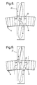
- the former 30, shown in figure 6, has a nose angle of the order of 45° and the cured stator core 22 is cut to form an opening 31 at the nose.
- the ends 32 of the stator core 22 are staggered, by a single rotor pole pitch, by putting chamfers 31 and 34 on opposite sides of each of the ends 32, figure 5.
- the wound asymmetric stator cores 22 offer the advantage that losses due to eddy currents generated when the flux impinges on the side faces of the stator cores 22 is minimised.
- the asymmetric shape is relatively easy to manufacture and the angled nose of the stator core 22 helps to minimise armature leakage.
- the angled nose allows the thickness of the stator core 22 to be reduced. Although the thickness of the stator core 22 is reduced at the angled nose the area of the stator core 22 is increased to span two rotor pole pieces hence flux saturation of the stator core 22 can be avoided.
- the stator core 22 can be inclined as shown in figure 7. Inclining the stator core 22 at a suitable angle in the stator frame 28 allows some reduction in the width of the stator core 22 and equalises the taper angle on each side of the pole pieces 32.
- an alternating current passes from terminal boxes 36 mounted on the stator frame 28 through the coils 24 to produce a rotating magnetic field.
- the rotor rotates as the magnets 20 follow the rotating magnetic field.
- the torque generated by each coil 24 is typically sinusoidal and falls to zero as the poles 20 and 32 attract.
- the multiple phases are provided generally by way of multiple discs and/or multiple phases per disc.
- the phases are arranged to give complementary torque so that the sinusoidal torque ripple cancels out.
- the flux that feeds the upper limb of the stator core 22 consists of the short path flux which is produced by magnet number 2 in figure 8 and also the long flux path which is produced by magnet number 1.
- the funnelling of the flux relies on both magnets 1 and 2 being able to feed the upper limb of the stator core 22.
- the short path flux consists of a local flux loop which simply links the armature winding 24 via a single stator core 22
- the long flux path links all the odd numbered magnets including magnets 1 and 3 as shown in figure 9.
- the long path flux thus links all the stator cores 22 and all the odd numbered magnets 20 to form a complete flux loop around the circumference of the rotor. In normal operation the long flux path will alternate around the machine (clockwise and anticlockwise).
- Each stator core 22 receives flux from two adjacent magnets.
- the flux is feed to the stator core 22 by the short and long path flux.
- the presence of the long path flux allows the use of a stator core 22 having a simplified geometry in accordance with the present invention.
- a motor constructed in accordance with the present invention offers a number of advantages over conventional motor designs. It is easier to manufacture as the stator frame 26 and the stator cores 22 can be built up as a complete sub-assembly before fitting the stator coils 24. The coils 24 are easier to wind and connect since there is easy access to the side faces of the coils 24.
- the rotor rim 16 comprises a single row and is considerably shortened. Some reduction in the overall length of the motor is achievable and the stator frame 28 consists of a substantial structure with each phase of the stator supported by deep flanges. The flanges have sufficient radial depth to give enough structural stiffness to resist distortion under radial shock. As the stator frame 26 and 28 is not subject to any net radial pull due to magnetic loading in the air gap the frame is not subject to the zero order stator frame vibration.
Landscapes
- Engineering & Computer Science (AREA)
- Power Engineering (AREA)
- Permanent Magnet Type Synchronous Machine (AREA)
- Iron Core Of Rotating Electric Machines (AREA)
- Permanent Field Magnets Of Synchronous Machinery (AREA)
Applications Claiming Priority (2)
| Application Number | Priority Date | Filing Date | Title |
|---|---|---|---|
| GB9516475 | 1995-08-11 | ||
| GBGB9516475.2A GB9516475D0 (en) | 1995-08-11 | 1995-08-11 | Electrical machine |
Publications (2)
| Publication Number | Publication Date |
|---|---|
| EP0763880A1 true EP0763880A1 (fr) | 1997-03-19 |
| EP0763880B1 EP0763880B1 (fr) | 2000-03-08 |
Family
ID=10779094
Family Applications (1)
| Application Number | Title | Priority Date | Filing Date |
|---|---|---|---|
| EP96305892A Expired - Lifetime EP0763880B1 (fr) | 1995-08-11 | 1996-08-12 | Machine électrique à flux magnétique transversal |
Country Status (6)
| Country | Link |
|---|---|
| US (1) | US5886449A (fr) |
| EP (1) | EP0763880B1 (fr) |
| JP (1) | JP3663014B2 (fr) |
| DE (1) | DE69606940T2 (fr) |
| ES (1) | ES2143143T3 (fr) |
| GB (1) | GB9516475D0 (fr) |
Cited By (4)
| Publication number | Priority date | Publication date | Assignee | Title |
|---|---|---|---|---|
| DE10240704A1 (de) * | 2002-09-04 | 2004-04-08 | Tirron-Elektronik Gmbh | Hochpolige Wechselstrommaschinen |
| US7868510B2 (en) * | 2007-03-30 | 2011-01-11 | Rittenhouse Norman P | High-efficiency wheel-motor utilizing molded magnetic flux channels with transverse-flux stator |
| EP2941813A4 (fr) * | 2013-01-04 | 2016-09-21 | David Calley | Stator en ruban métallique et moteur comprenant celui-ci |
| FR3057412A1 (fr) * | 2016-10-07 | 2018-04-13 | Peugeot Citroen Automobiles Sa | Moteur electrique a double accouplement polaire |
Families Citing this family (14)
| Publication number | Priority date | Publication date | Assignee | Title |
|---|---|---|---|---|
| DE60335356D1 (de) * | 2002-04-11 | 2011-01-27 | Eocycle Technologies Inc | Elektrische maschine mit transversalem magnetischem fluss und verzahnungsrotor |
| NZ540310A (en) * | 2004-06-19 | 2006-03-31 | Inventio Ag | Drive for a lift installation |
| WO2008141214A1 (fr) * | 2007-05-09 | 2008-11-20 | Motor Excellence, Llc. | Dispositifs de génération de sortie électriques et dispositifs électriques d'entraînement avec une fuite de flux réduite utilisant des composants formant aimant permanent, et leurs procédés de fabrication et d'utilisation |
| US7973446B2 (en) * | 2007-05-09 | 2011-07-05 | Motor Excellence, Llc | Electrical devices having tape wound core laminate rotor or stator elements |
| EP2342803A2 (fr) * | 2008-11-03 | 2011-07-13 | Motor Excellence, LLC | Concepts de rotor de système d écoulement transversal et/ou commuté |
| JP5507967B2 (ja) * | 2009-11-09 | 2014-05-28 | 株式会社日立製作所 | 回転電機 |
| WO2011115632A1 (fr) | 2010-03-15 | 2011-09-22 | Motor Excellence Llc | Systèmes à flux transversal et/ou à flux commuté, configurés de façon à réduire les déperditions de flux, à réduire les déperditions d'hystérésis et à réaliser une adaptation de phase |
| WO2011115633A1 (fr) | 2010-03-15 | 2011-09-22 | Motor Excellence Llc | Systèmes à flux transversal et/ou à flux commuté pour vélos électriques |
| WO2011115634A1 (fr) | 2010-03-15 | 2011-09-22 | Motor Excellence Llc | Systèmes à flux transversal et/ou à flux commuté comprenant une caractéristique de décalage de phase |
| US8952590B2 (en) | 2010-11-17 | 2015-02-10 | Electric Torque Machines Inc | Transverse and/or commutated flux systems having laminated and powdered metal portions |
| CN103477538A (zh) | 2010-11-17 | 2013-12-25 | 电动转矩机器公司 | 具有分段定子层压件的横向和/或换向磁通系统 |
| US8854171B2 (en) | 2010-11-17 | 2014-10-07 | Electric Torque Machines Inc. | Transverse and/or commutated flux system coil concepts |
| US20140265714A1 (en) * | 2013-03-13 | 2014-09-18 | Remy Technologies, L.L.C. | Transverse flux stator core manufacture |
| JP6539465B2 (ja) | 2015-03-19 | 2019-07-03 | 株式会社東芝 | 横方向磁束型回転電機 |
Citations (4)
| Publication number | Priority date | Publication date | Assignee | Title |
|---|---|---|---|---|
| DE4138014C1 (en) * | 1991-11-19 | 1993-02-04 | Herbert Prof. Dr.-Ing. 3300 Braunschweig De Weh | Electromechanical power converter in rotary or linear form - has permanent magnets assembled in rotor driven by AC stator winding with pole elements |
| WO1995004399A1 (fr) * | 1993-07-31 | 1995-02-09 | Herbert Weh | Machine electrique |
| DE19507233A1 (de) * | 1994-04-15 | 1995-10-26 | Weh Herbert Prof Dr Ing Dr H C | Transversalflußmaschine mit Permanenterregung und mehrsträngiger Ankerwicklung |
| DE4430139A1 (de) * | 1994-08-25 | 1996-02-29 | Weh Herbert Prof Dr Ing Dr H C | Transversalflußmaschine mit passivem Rotor |
Family Cites Families (11)
| Publication number | Priority date | Publication date | Assignee | Title |
|---|---|---|---|---|
| US567423A (en) * | 1896-09-08 | thuey | ||
| US630333A (en) * | 1898-11-08 | 1899-08-08 | Robert W Beebe | Diphase electric motor. |
| AT216089B (de) * | 1959-09-07 | 1961-07-10 | Elektro Motoren Ag | Wechselstrommaschine |
| GB953066A (en) * | 1960-05-25 | 1964-03-25 | Atomic Energy Authority Uk | Improvements in or relating to magnetic drive systems |
| US3700942A (en) * | 1971-02-03 | 1972-10-24 | Max Alth | Self-starting synchronous motors |
| US3719842A (en) * | 1971-05-28 | 1973-03-06 | Mallory & Co Inc P R | Synchronous motor |
| US3786291A (en) * | 1972-10-02 | 1974-01-15 | Mc Graw Edison Co | Synchronous motor |
| CH665922A5 (fr) * | 1985-05-10 | 1988-06-15 | Portescap | Moteur electrique synchrone a rotor en forme de disque. |
| DE3705089A1 (de) * | 1987-02-13 | 1988-08-25 | Weh Herbert | Transversalflussmaschine in sammleranordnung |
| CH672566A5 (fr) * | 1987-06-26 | 1989-11-30 | Portescap | |
| AU641822B2 (en) * | 1990-11-23 | 1993-09-30 | J.M. Voith Gmbh | Electric motor |
-
1995
- 1995-08-11 GB GBGB9516475.2A patent/GB9516475D0/en active Pending
-
1996
- 1996-08-06 JP JP20709096A patent/JP3663014B2/ja not_active Expired - Fee Related
- 1996-08-08 US US08/694,427 patent/US5886449A/en not_active Expired - Lifetime
- 1996-08-12 ES ES96305892T patent/ES2143143T3/es not_active Expired - Lifetime
- 1996-08-12 DE DE69606940T patent/DE69606940T2/de not_active Expired - Lifetime
- 1996-08-12 EP EP96305892A patent/EP0763880B1/fr not_active Expired - Lifetime
Patent Citations (4)
| Publication number | Priority date | Publication date | Assignee | Title |
|---|---|---|---|---|
| DE4138014C1 (en) * | 1991-11-19 | 1993-02-04 | Herbert Prof. Dr.-Ing. 3300 Braunschweig De Weh | Electromechanical power converter in rotary or linear form - has permanent magnets assembled in rotor driven by AC stator winding with pole elements |
| WO1995004399A1 (fr) * | 1993-07-31 | 1995-02-09 | Herbert Weh | Machine electrique |
| DE19507233A1 (de) * | 1994-04-15 | 1995-10-26 | Weh Herbert Prof Dr Ing Dr H C | Transversalflußmaschine mit Permanenterregung und mehrsträngiger Ankerwicklung |
| DE4430139A1 (de) * | 1994-08-25 | 1996-02-29 | Weh Herbert Prof Dr Ing Dr H C | Transversalflußmaschine mit passivem Rotor |
Cited By (8)
| Publication number | Priority date | Publication date | Assignee | Title |
|---|---|---|---|---|
| DE10240704A1 (de) * | 2002-09-04 | 2004-04-08 | Tirron-Elektronik Gmbh | Hochpolige Wechselstrommaschinen |
| DE10240704B4 (de) * | 2002-09-04 | 2006-04-27 | Tirron-Elektronik Gmbh | Hochpolige, mehrphasige Wechselstrommaschine mit transversaler Flussführung |
| US7868510B2 (en) * | 2007-03-30 | 2011-01-11 | Rittenhouse Norman P | High-efficiency wheel-motor utilizing molded magnetic flux channels with transverse-flux stator |
| EP2941813A4 (fr) * | 2013-01-04 | 2016-09-21 | David Calley | Stator en ruban métallique et moteur comprenant celui-ci |
| US9680339B2 (en) | 2013-01-04 | 2017-06-13 | Moog Inc. | Metal ribbon stator and motor comprising same |
| US10320246B2 (en) | 2013-01-04 | 2019-06-11 | Moog Inc. | Metal ribbon stator and motor comprising same |
| US11081913B2 (en) | 2013-01-04 | 2021-08-03 | Moog Inc. | Metal ribbon stator and motor comprising same |
| FR3057412A1 (fr) * | 2016-10-07 | 2018-04-13 | Peugeot Citroen Automobiles Sa | Moteur electrique a double accouplement polaire |
Also Published As
| Publication number | Publication date |
|---|---|
| ES2143143T3 (es) | 2000-05-01 |
| JPH09117116A (ja) | 1997-05-02 |
| EP0763880B1 (fr) | 2000-03-08 |
| GB9516475D0 (en) | 1995-10-11 |
| DE69606940D1 (de) | 2000-04-13 |
| DE69606940T2 (de) | 2000-07-20 |
| JP3663014B2 (ja) | 2005-06-22 |
| US5886449A (en) | 1999-03-23 |
Similar Documents
| Publication | Publication Date | Title |
|---|---|---|
| US5973436A (en) | Electrical machine | |
| US20240136904A1 (en) | Flux machine | |
| US5886449A (en) | Electrical machine | |
| US5177392A (en) | High efficiency, low reactance disk-type machine including an improved rotor and stator | |
| EP0365535B1 (fr) | Unite de stator pour machine dynamo-electrique | |
| US4556809A (en) | Combination synchronous and asynchronous electric motor | |
| US7250702B2 (en) | Rotary electric machine comprising a stator and two rotors | |
| US20130270955A1 (en) | Electromagnetic machine | |
| US4538086A (en) | Stator for an electromagnetic machine | |
| US4510680A (en) | Method of making a permanent magnet rotor | |
| US5712521A (en) | Hybrid synchronous machine with transverse magnetic flux | |
| EP0489859B1 (fr) | Rotor a pertes par ventilation reduites | |
| US7518278B2 (en) | High strength undiffused brushless machine and method | |
| EP0762618B1 (fr) | Machine électrique à flux magnétique transversal | |
| US3418506A (en) | Axial airgap motors and generators | |
| WO2011055124A1 (fr) | Machines électriques | |
| JPH1094230A (ja) | 外転型集中巻回転電機とそれを用いた電動車両 | |
| US4480207A (en) | Permanent magnet rotor and method of making same | |
| US3728566A (en) | Salient pole rotor construction with removable pole tips | |
| JP2957346B2 (ja) | アキシャルギャップ回転電機 | |
| KR100364705B1 (ko) | 동기유도 전동기의 회전자 | |
| CN121713354A (zh) | 同步电机的轴向磁通感应器 | |
| AU603448B2 (en) | Stator assembly for dynamoelectric machine | |
| GB2139823A (en) | Stator for an electromagnetic machine | |
| JPH0710160B2 (ja) | 交流電動機 |
Legal Events
| Date | Code | Title | Description |
|---|---|---|---|
| PUAI | Public reference made under article 153(3) epc to a published international application that has entered the european phase |
Free format text: ORIGINAL CODE: 0009012 |
|
| AK | Designated contracting states |
Kind code of ref document: A1 Designated state(s): CH DE ES FI FR GB IT LI SE |
|
| 17P | Request for examination filed |
Effective date: 19970809 |
|
| 17Q | First examination report despatched |
Effective date: 19980817 |
|
| GRAG | Despatch of communication of intention to grant |
Free format text: ORIGINAL CODE: EPIDOS AGRA |
|
| GRAG | Despatch of communication of intention to grant |
Free format text: ORIGINAL CODE: EPIDOS AGRA |
|
| RTI1 | Title (correction) |
Free format text: TRANSVERSE FLUX ELECTRICAL MACHINE |
|
| GRAG | Despatch of communication of intention to grant |
Free format text: ORIGINAL CODE: EPIDOS AGRA |
|
| GRAH | Despatch of communication of intention to grant a patent |
Free format text: ORIGINAL CODE: EPIDOS IGRA |
|
| GRAH | Despatch of communication of intention to grant a patent |
Free format text: ORIGINAL CODE: EPIDOS IGRA |
|
| GRAA | (expected) grant |
Free format text: ORIGINAL CODE: 0009210 |
|
| ITF | It: translation for a ep patent filed | ||
| AK | Designated contracting states |
Kind code of ref document: B1 Designated state(s): CH DE ES FI FR GB IT LI SE |
|
| REG | Reference to a national code |
Ref country code: CH Ref legal event code: NV Representative=s name: KIRKER & CIE SA Ref country code: CH Ref legal event code: EP |
|
| ET | Fr: translation filed | ||
| REF | Corresponds to: |
Ref document number: 69606940 Country of ref document: DE Date of ref document: 20000413 |
|
| REG | Reference to a national code |
Ref country code: ES Ref legal event code: FG2A Ref document number: 2143143 Country of ref document: ES Kind code of ref document: T3 |
|
| PLBE | No opposition filed within time limit |
Free format text: ORIGINAL CODE: 0009261 |
|
| STAA | Information on the status of an ep patent application or granted ep patent |
Free format text: STATUS: NO OPPOSITION FILED WITHIN TIME LIMIT |
|
| 26N | No opposition filed | ||
| REG | Reference to a national code |
Ref country code: GB Ref legal event code: IF02 |
|
| PGFP | Annual fee paid to national office [announced via postgrant information from national office to epo] |
Ref country code: CH Payment date: 20110824 Year of fee payment: 16 |
|
| PGFP | Annual fee paid to national office [announced via postgrant information from national office to epo] |
Ref country code: DE Payment date: 20110823 Year of fee payment: 16 Ref country code: FI Payment date: 20110812 Year of fee payment: 16 Ref country code: ES Payment date: 20110812 Year of fee payment: 16 Ref country code: FR Payment date: 20110901 Year of fee payment: 16 Ref country code: GB Payment date: 20110819 Year of fee payment: 16 Ref country code: SE Payment date: 20110824 Year of fee payment: 16 |
|
| PGFP | Annual fee paid to national office [announced via postgrant information from national office to epo] |
Ref country code: IT Payment date: 20110824 Year of fee payment: 16 |
|
| REG | Reference to a national code |
Ref country code: CH Ref legal event code: PL |
|
| REG | Reference to a national code |
Ref country code: SE Ref legal event code: EUG |
|
| GBPC | Gb: european patent ceased through non-payment of renewal fee |
Effective date: 20120812 |
|
| PG25 | Lapsed in a contracting state [announced via postgrant information from national office to epo] |
Ref country code: SE Free format text: LAPSE BECAUSE OF NON-PAYMENT OF DUE FEES Effective date: 20120813 Ref country code: LI Free format text: LAPSE BECAUSE OF NON-PAYMENT OF DUE FEES Effective date: 20120831 Ref country code: FI Free format text: LAPSE BECAUSE OF NON-PAYMENT OF DUE FEES Effective date: 20120812 Ref country code: CH Free format text: LAPSE BECAUSE OF NON-PAYMENT OF DUE FEES Effective date: 20120831 |
|
| REG | Reference to a national code |
Ref country code: FR Ref legal event code: ST Effective date: 20130430 |
|
| PG25 | Lapsed in a contracting state [announced via postgrant information from national office to epo] |
Ref country code: IT Free format text: LAPSE BECAUSE OF NON-PAYMENT OF DUE FEES Effective date: 20120812 |
|
| PG25 | Lapsed in a contracting state [announced via postgrant information from national office to epo] |
Ref country code: GB Free format text: LAPSE BECAUSE OF NON-PAYMENT OF DUE FEES Effective date: 20120812 Ref country code: DE Free format text: LAPSE BECAUSE OF NON-PAYMENT OF DUE FEES Effective date: 20130301 |
|
| PG25 | Lapsed in a contracting state [announced via postgrant information from national office to epo] |
Ref country code: FR Free format text: LAPSE BECAUSE OF NON-PAYMENT OF DUE FEES Effective date: 20120831 |
|
| REG | Reference to a national code |
Ref country code: DE Ref legal event code: R119 Ref document number: 69606940 Country of ref document: DE Effective date: 20130301 |
|
| REG | Reference to a national code |
Ref country code: ES Ref legal event code: FD2A Effective date: 20131021 |
|
| PG25 | Lapsed in a contracting state [announced via postgrant information from national office to epo] |
Ref country code: ES Free format text: LAPSE BECAUSE OF NON-PAYMENT OF DUE FEES Effective date: 20120813 |