EP0764262B1 - Appareil pour effectuer une analyse spectrale d'une source de lumiere optique par detection d'image et separation d'ordres spectraux speciaux - Google Patents
Appareil pour effectuer une analyse spectrale d'une source de lumiere optique par detection d'image et separation d'ordres spectraux speciaux Download PDFInfo
- Publication number
- EP0764262B1 EP0764262B1 EP95919724A EP95919724A EP0764262B1 EP 0764262 B1 EP0764262 B1 EP 0764262B1 EP 95919724 A EP95919724 A EP 95919724A EP 95919724 A EP95919724 A EP 95919724A EP 0764262 B1 EP0764262 B1 EP 0764262B1
- Authority
- EP
- European Patent Office
- Prior art keywords
- component
- prismatic
- imaging
- components
- angle
- Prior art date
- Legal status (The legal status is an assumption and is not a legal conclusion. Google has not performed a legal analysis and makes no representation as to the accuracy of the status listed.)
- Expired - Lifetime
Links
- 230000003287 optical effect Effects 0.000 title claims abstract description 159
- 230000003595 spectral effect Effects 0.000 title claims abstract description 130
- 238000000926 separation method Methods 0.000 title claims abstract description 12
- 238000010183 spectrum analysis Methods 0.000 title claims abstract description 10
- 238000001514 detection method Methods 0.000 title description 2
- 238000003384 imaging method Methods 0.000 claims abstract description 113
- 238000001228 spectrum Methods 0.000 claims abstract description 61
- 239000006185 dispersion Substances 0.000 claims abstract description 52
- 230000005855 radiation Effects 0.000 claims abstract description 40
- 239000000463 material Substances 0.000 claims abstract description 29
- 238000009827 uniform distribution Methods 0.000 claims abstract description 12
- 230000004075 alteration Effects 0.000 claims description 12
- 230000009467 reduction Effects 0.000 claims description 10
- 230000004304 visual acuity Effects 0.000 claims description 7
- 229910001632 barium fluoride Inorganic materials 0.000 claims description 4
- VYPSYNLAJGMNEJ-UHFFFAOYSA-N Silicium dioxide Chemical compound O=[Si]=O VYPSYNLAJGMNEJ-UHFFFAOYSA-N 0.000 claims description 2
- OYLGJCQECKOTOL-UHFFFAOYSA-L barium fluoride Chemical compound [F-].[F-].[Ba+2] OYLGJCQECKOTOL-UHFFFAOYSA-L 0.000 claims 2
- 239000007788 liquid Substances 0.000 claims 2
- 238000002835 absorbance Methods 0.000 claims 1
- 238000002485 combustion reaction Methods 0.000 claims 1
- 238000010891 electric arc Methods 0.000 claims 1
- 238000004880 explosion Methods 0.000 claims 1
- 239000005350 fused silica glass Substances 0.000 claims 1
- 239000007789 gas Substances 0.000 claims 1
- 229910052736 halogen Inorganic materials 0.000 claims 1
- 150000002367 halogens Chemical class 0.000 claims 1
- PQXKHYXIUOZZFA-UHFFFAOYSA-M lithium fluoride Chemical compound [Li+].[F-] PQXKHYXIUOZZFA-UHFFFAOYSA-M 0.000 claims 1
- 239000007787 solid Substances 0.000 claims 1
- 230000014509 gene expression Effects 0.000 description 20
- 230000005540 biological transmission Effects 0.000 description 7
- 230000008030 elimination Effects 0.000 description 7
- 238000003379 elimination reaction Methods 0.000 description 7
- 206010010071 Coma Diseases 0.000 description 6
- 201000009310 astigmatism Diseases 0.000 description 5
- 238000000034 method Methods 0.000 description 4
- 238000009828 non-uniform distribution Methods 0.000 description 3
- 238000004364 calculation method Methods 0.000 description 2
- 238000006243 chemical reaction Methods 0.000 description 2
- 238000009826 distribution Methods 0.000 description 2
- 230000004048 modification Effects 0.000 description 2
- 238000012986 modification Methods 0.000 description 2
- 238000012634 optical imaging Methods 0.000 description 2
- 238000010276 construction Methods 0.000 description 1
- 230000004069 differentiation Effects 0.000 description 1
- 239000011521 glass Substances 0.000 description 1
- 239000003292 glue Substances 0.000 description 1
- 238000013178 mathematical model Methods 0.000 description 1
- 239000000203 mixture Substances 0.000 description 1
- 238000005498 polishing Methods 0.000 description 1
- 239000010453 quartz Substances 0.000 description 1
- 230000035945 sensitivity Effects 0.000 description 1
- 238000006467 substitution reaction Methods 0.000 description 1
Images


Classifications
-
- G—PHYSICS
- G01—MEASURING; TESTING
- G01J—MEASUREMENT OF INTENSITY, VELOCITY, SPECTRAL CONTENT, POLARISATION, PHASE OR PULSE CHARACTERISTICS OF INFRARED, VISIBLE OR ULTRAVIOLET LIGHT; COLORIMETRY; RADIATION PYROMETRY
- G01J3/00—Spectrometry; Spectrophotometry; Monochromators; Measuring colours
- G01J3/12—Generating the spectrum; Monochromators
- G01J3/14—Generating the spectrum; Monochromators using refracting elements, e.g. prisms
- G01J3/16—Generating the spectrum; Monochromators using refracting elements, e.g. prisms with autocollimation
-
- G—PHYSICS
- G01—MEASURING; TESTING
- G01J—MEASUREMENT OF INTENSITY, VELOCITY, SPECTRAL CONTENT, POLARISATION, PHASE OR PULSE CHARACTERISTICS OF INFRARED, VISIBLE OR ULTRAVIOLET LIGHT; COLORIMETRY; RADIATION PYROMETRY
- G01J3/00—Spectrometry; Spectrophotometry; Monochromators; Measuring colours
- G01J3/02—Details
- G01J3/0205—Optical elements not provided otherwise, e.g. optical manifolds, diffusers, windows
-
- G—PHYSICS
- G01—MEASURING; TESTING
- G01J—MEASUREMENT OF INTENSITY, VELOCITY, SPECTRAL CONTENT, POLARISATION, PHASE OR PULSE CHARACTERISTICS OF INFRARED, VISIBLE OR ULTRAVIOLET LIGHT; COLORIMETRY; RADIATION PYROMETRY
- G01J3/00—Spectrometry; Spectrophotometry; Monochromators; Measuring colours
- G01J3/12—Generating the spectrum; Monochromators
- G01J3/18—Generating the spectrum; Monochromators using diffraction elements, e.g. grating
-
- G—PHYSICS
- G01—MEASURING; TESTING
- G01J—MEASUREMENT OF INTENSITY, VELOCITY, SPECTRAL CONTENT, POLARISATION, PHASE OR PULSE CHARACTERISTICS OF INFRARED, VISIBLE OR ULTRAVIOLET LIGHT; COLORIMETRY; RADIATION PYROMETRY
- G01J3/00—Spectrometry; Spectrophotometry; Monochromators; Measuring colours
- G01J3/12—Generating the spectrum; Monochromators
- G01J2003/1204—Grating and filter
-
- G—PHYSICS
- G01—MEASURING; TESTING
- G01J—MEASUREMENT OF INTENSITY, VELOCITY, SPECTRAL CONTENT, POLARISATION, PHASE OR PULSE CHARACTERISTICS OF INFRARED, VISIBLE OR ULTRAVIOLET LIGHT; COLORIMETRY; RADIATION PYROMETRY
- G01J3/00—Spectrometry; Spectrophotometry; Monochromators; Measuring colours
- G01J3/12—Generating the spectrum; Monochromators
- G01J3/18—Generating the spectrum; Monochromators using diffraction elements, e.g. grating
- G01J2003/1828—Generating the spectrum; Monochromators using diffraction elements, e.g. grating with order sorter or prefilter
-
- G—PHYSICS
- G01—MEASURING; TESTING
- G01J—MEASUREMENT OF INTENSITY, VELOCITY, SPECTRAL CONTENT, POLARISATION, PHASE OR PULSE CHARACTERISTICS OF INFRARED, VISIBLE OR ULTRAVIOLET LIGHT; COLORIMETRY; RADIATION PYROMETRY
- G01J3/00—Spectrometry; Spectrophotometry; Monochromators; Measuring colours
- G01J3/12—Generating the spectrum; Monochromators
- G01J3/18—Generating the spectrum; Monochromators using diffraction elements, e.g. grating
- G01J3/24—Generating the spectrum; Monochromators using diffraction elements, e.g. grating using gratings profiled to favour a specific order
Definitions
- the present invention comprises an apparatus for carrying out spectral analysis of optical radiation emitted from a light source, more particularly an apparatus comprising of a spectral detector with an entrance aperture for the radiation from a light source, means for optical imaging, a diffraction grating for wavelength dispersion of the radiation, an order sorting means for separation of the spectral orders from the diffraction grating, which means disperses the radiation in a direction orthogonal to that of the diffraction grating, a second means for optical imaging, and finally detecting means for recording of the spectrum of the light source, said spectrum being divided into order spectra through said order sorting means.
- Diffraction gratings for wavelength dispersion, i. e. separation of optical radiation into wavelength components, is a well known technique.
- Diffraction gratings are most effective optical elements for carrying out wavelength dispersion.
- these have the drawback that spectra from several so called spectral orders result in ambiguities in the analysis of a spectrum.
- Modern optical sensors are sensitive for optical radiation simultaneously in the wavelength range from the so called vacuum ultra violet (VUV), at wavelengths below 200 nm, to the near infrared (NIR), at wavelengths above 700 nm.
- VUV vacuum ultra violet
- NIR near infrared
- One solution to this problem can be several optical filters placed suitably in the vicinity of the focal plane of the optical instrument. Through this arrangement one can in principle extend the recording capability in a single spectral order.
- diffraction gratings manufactured either holographically or through ruling, show a variation of the efficiency by which the optical radiation is dispersed. This so called diffraction efficiency, i. e. the ratio between the intensity of the dispersed light and that of the incident light at a certain wavelength, has a maximum at a certain wavelength given in general in the first spectral order.
- the blaze wavelength is a quantity characteristic for the diffraction grating, and depends on both the distance between the grating grooves and their shape, as well as on the polarisation of the optical radiation. In the selection of a diffraction grating this wavelength is chosen to lie in the wavelength range of the instrument. When the wavelength to be recorded diverges considerably from the blaze wavelength, the diffraction efficiency of the grating is substantially reduced.
- UV ultra violet
- NIR near infrared
- the order spectra can be separated from each other at the focal surface in the recording.
- a spectral apparatus that records the spectrum sequentially such as a monochromator
- this separation can be made with for instance filters placed in front of the entrance aperture of the monochromator.
- order sorter an additional wavelength dispersing optical element, called order sorter, is to be introduced in the ray path prior to the focal plane. The direction of the wavelength dispersion must then be made orthogonal to that of the diffraction grating.
- Order sorters are found in SE-C-359 648 and are also described by A. Danielsson and P. Lindblom in Physica Scripta No. 5 (1972) page 227 and by S. Engman, P. Lindblom and B. Sandberg in Physica Scripta No. 24 (1981) page 965.
- Order sorters of the type discussed either consisting of a single diffraction grating or a combination of a diffraction grating and a prism are therefore impossible to use.
- These order sorting means were mainly designed for the detection with an image tube with sequential read-out implying that filters could be used during read-out for the purpose of separating disturbances from other orders of the grating in the order sorter. With simultaneous recording of the whole required wavelength range order sorters of this kind are hard or impossible to use.
- the shortest distance between the order spectra on the focal surface determines the height of the entrance aperture of the spectral apparatus.
- the detector such as a CCD sensor
- the non-uniform distribution of the order spectra results in a restriction of the sensitivity of the spectral apparatus, i.e. a restriction of the amount of optical radiation that it can detect. Very large wavelength ranges thus become impossible to record simultaneously.
- Another consequence of said non-uniform distribution is that the surface of the sensor is utilised inefficiently.
- the facts above also bring forward the special demands that order sorting of the spectral orders put on the optical image of the entrance aperture on the focal plane.
- the height of the entrance aperture has to be chosen so that the corresponding height of its image on the focal plane is smaller than the shortest distance between the order spectra. If that is not the case the orders spectra will mix in the recording, i.e. one receives a "cross talk" from the spectral signal of the neighbouring order spectra.
- spectroscopic applications generally require that the spectrum can be measured without disturbances in intensity ranges where the weakest signal is 1/10000 or less than the strongest signal, even a small cross talk from one order spectrum to another is very disturbing.
- a further aberration of the optical image that is disturbing in optical spectral instruments is so called coma.
- This aberration appears as an asymmetric broadening of the optical image.
- this aberration is reduced or eliminated through the present invention.
- the detector unit of spectral instruments is often expensive. Its light sensitive surface, which normally has a rectangular shape also has a restricted size. In relation to initially specified spectral properties, it is generally hard to make a choice of the main parameters of the spectral apparatus so that this surface is utilised in an optimal way. This difficulty is also eliminated or reduced be the present invention.
- the purpose of the present invention is to eliminate the above mentioned, and other drawbacks, in connection to an apparatus of the type mentioned in the introduction.
- said order sorting component consists of at least two refractive optical components, manufactured from different optical materials which components together with the diffraction grating and the imaging optical components are arranged to coact to produce a substantially uniform distribution of said order spectra on said detector, and a substantially stigmatic image of the entrance aperture in at least one point on said detector.
- the invention makes the order sorter able to seperate the different order spectra unambiguously and with a substantially uniform distribution on the detector, and to simultaneously eliminate or reduce the astigmatic optical aberration.
- Another optical aberration which causes a broadening of the spectral image of the entrance aperture and consequently a reduction of the spectral resolution, namely coma, is eliminated or reduced through the present invention.
- the invention makes it possible to optimise the use of the surface of the detector unit.
- Fig. 1 shows a three dimensional view of a spectral apparatus according to the invention consisting of a light source 11 and a spectral detector 1 that contains an entrance aperture 10.
- Lines marked by arrows denote in general central rays in the spectral detector.
- first and second imaging optical components 12, 15 two mirrors with reflecting front surfaces, each with a concave, such as spherical or toroidal shape, are used.
- the diffraction grating 14 has been placed.
- said grating has a plane reflecting surface shape. Rays emerging from the same point on the diffraction grating define a plane, called the plane of dispersion.
- This plane containing the rays 141 and 142 in Fig. 1, is orthogonal to the grooves of the grating.
- the orientation of the mirrors in Fig. 1 has been chosen so that both their planes of reflection, meaning the planes defined by the rays before 121, 151, and after 122, 152, the reflection in the central points of the mirrors, are substantially parallel to the direction that the wavelength dispersion of the grating defines at the mirrors.
- the apparatus of Fig. 1 thus shows an optical mounting of Type II, defined below as a guide line for the application of the mathematical relations describing the invention.
- the order sorting unit 13 in accordance with the invention also placed in the ray path between the mirrors 12 and 15, consists of two prismatic components 131 and 132, manufactured from different optical materials, such as, for instance LiF and BaF 2 , alternatively LiF and Quartz, respectively.
- the prisms 131 and 132 are mounted so that their wavelength dispersions act in a direction substantially orthogonal to the plane of dispersion of the diffraction grating 14.
- the prisms 131 and 132, that in the shown example of Fig. 1 each being manufactured with one reflecting surface, are orientated mutually so that the wavelength dispersion of one of the prisms 131 counter acts that of the other 132.
- Fig. 1 each being manufactured with one reflecting surface
- the detector unit 16 is the detector unit 16 and its light sensitive surface 161 upon which the spectral orders from the diffraction grating, are focused into, from each separated order spectra, having a distribution substantially uniform in accordance with the invention.
- Assignments as well as orientation and positioning of said components, contained in the spectral detector 1, namely the entrance aperture 10, the mirrors 12, 15, the diffraction grating 14, the prisms 131, 132 and the detector 16, have been chosen so that the below given mathematical relations (18), (21), (26), (28), (30), (31) and (32) are substantially satisfied simultaneously. Satisfying the mathematical relations (21) and (26) results in, that the order spectra are focused on the detector 16 with substantially uniform distribution and at substantially stigmatic imaging, in accordance with the invention.
- FIG. 1 Another embodiment of the spectral detector 1 in Fig. 1 in accordance with the invention is shown in the three dimensional view in figure 2.
- Fig. 2 shows the entrance aperture 10, the first and second imaging optical components 12 and 15, in the shown example of Fig. 2 being concave mirrors with for instance spherical or toroidal surface shapes.
- the diffraction grating 14 and the detector unit 16 are also shown in the embodimentealisation of Fig. 2.
- the rays 141 and 151 define, in Fig. 2, as well the plane of dispersion of the diffraction grating 14.
- the mirrors 12 and 15 have in Fig.
- Fig. 2 has been mounted so that both their planes of reflection, meaning the planes defined by the rays before 121, 151 and after 122, 152 reflection in the central points of the mirrors, are substantially orthogonal to the direction defined at the mirrors by the wavelength dispersion of the grating.
- said planes of reflection are substantially parallel to the grooves of the diffraction grating.
- the apparatus of Fig. 2 thus shows an optical mounting of type I, defined below as a guide line for the application of the mathematical relations describing the invention.
- the prisms 131 and 132 of the order sorting unit 13 are in Fig. 2 arranged in accordance with the invention, so that two of their surfaces are in optical contact with each other as shown in the Fig. 3e below.
- these prisms in Fig. 2 form a composed order sorting unit 13.
- assignments, orientation and positioning of said components, contained in the spectral detector 1, namely the entrance aperture 10, the mirrors 12,15, the diffraction grating 14, the prisms 131, 132 and the detector 16 have been chosen so that the below given mathematical relations (18), (21); (25), (27), (30), (31) and (32) are substantially satisfied simultaneously.
- Satisfying the mathematical relations (21) and (25) results in, that the order spectra are focused on the detector 16 with substantially uniform distribution and at substantially stigmatic imaging in accordance with the invention.
- Satisfying the relation 27 results additionally in, that the comatic aberration is eliminated or reduced in said image, in accordance with the invention.
- Fig. 3 shows cross sectional views of some different embodiments of the order sorting unit 13 in accordance with the invention.
- Fig. 3a shows two, from different materials manufactured prisms, used in transmission that counter act each other.
- the dotted lines denote normals to the prism surfaces and the, by arrows marked broken line, denotes a general ray.
- a general angle of incidence has been marked by ⁇ 1 and a general angle of refraction by ⁇ 1 .
- the corresponding general angles for the prism 132 in Fig. 3a are ⁇ 2 and ⁇ 2 , respectively.
- the quantity n 1 denotes the refractive index for the optical material of prism 131 and correspondingly the quantity n 2 the refractive index for the material of prism 132.
- Fig. 3b shows aa embodiment of the order sorting unit 13 according to the invention, consisting of three separately mounted prisms 131, 132 and 133 where prisms 131 and 133 have co-acting wavelength dispersions whereas that of prism 132 is counter acting.
- This alternative can for instance be chosen when a large separation of the spectral orders is required in an embodiment with separately mounted transmission prisms.
- Fig. 3c shows an embodiment analogous to that of Fig 3a, however, with the difference that the prisms 131 and 132 are mounted so that two of their surfaces are in optical contact with each other.
- This optical contact can be achieved either with a glue, transparent in the wavelength range intended for the apparatus, or through polishing of said surfaces to the same shape, with sufficiently high surface accuracy to allow said surfaces to be pressed into contact with each other.
- the order sorting unit in Fig. 3c thus becomes a combined single optical component.
- This embodiment of the order sorting unit 13 can be chosen as an alternative to that of Fig. 3a, when it is important to reduce reflection losses in the prisms surfaces or alternatively reduce the total number of components in the spectral apparatus 1.
- Fig. 3d shows an embodiment analogous to that of Fig 3b, consisting of two co-acting prisms 131,133 and one counter acting prism 132, with the difference that the prism 132 has been mounted with the first of its optical surfaces in contact with the second optical surface of prism 131 and with its second optical surface in contact with the first optical surface of prism 133.
- the order sorting unit 13 in Fig. 3d becomes a combined single optical component as well.
- This embodiment of the order sorting unit 13 can be chosen as an alternative to that of Fig. 3b, when it is important to reduce reflection losses in the prism surfaces or alternatively reduce the total number of components in the spectral apparatus 1.
- Fig. 3e shows an embodiment analogous to that of Fig 3c, having the prisms 131 and 132 mounted with two of their surfaces in optical contact with each other.
- the free surface of the second prism 132 has been made reflecting, causing the optical radiation, after the passage through the prisms, to be reflected in said surface and to be made to pass through both the prisms a second time, thus emerging from prisms in opposite direction to that of the incident optical radiation.
- Said reflecting surface can also be ground and polished into a non-plane, for instance spherical, surface.
- the embodiment shown in Fig. 3e with a plane reflecting surface has been used in the spectral detector according to the invention shown in Fig. 2.
- Fig. 3e As the optical radiation, shown by the broken line marked with arrows, passes the prism 131 twice, the embodiment of Fig. 3e is, in the mathematical description below, considered as consisting of three prismatic components.
- the refractive angle of prism 132 has been denoted by A 2 /2 in Fig. 3e, because this prism corresponds to a transmission prism with a refractive angle A 2 .
- this embodiment is equivalent to one with three prisms in transmission as shown in Fig. 3d, it is effective for achieving powerful separation of the spectral orders in accordance with the invention.
- a good choice for the material of prism 131 is LiF and for the material of prism 132 is BaF 2 . If said spectral detector is designed for the wavelength range 380 nm to 1050 nm, a good choice is the Schott glass type LaK 31 for prism 131 and type SF 18 for prism 132.
- Fig. 3f shows an example of a similar embodiment as that shown in Fig. 3e, however, made with three prisms in the same way as shown in Fig. 3b.
- the prism 131 has one optical surface in contact with the first surface of prism 132 and its other optical surface in contact with the first surface of prism 133.
- the second surface of prism 133 has been made reflecting.
- the embodiment of Fig. 3f is, in the mathematical description below, considered as consisting of five prismatic components.
- the refractive angle of prism 133 has been denoted by A 3 /2 in Fig.
- this prism corresponds to a transmission prism with a refractive angle A 3 .
- this embodiment is equivalent to one with five prisms in transmission as shown in Fig. 3f, it is effective for achieving powerful separation of the spectral orders in accordance with the invention.
- Fig. 3g shows finally an embodiment where both prisms 131, 132 are mounted separately from each other.
- both prisms are manufactured in such a way that each has one reflecting surface, that each can have a non-plane shape.
- the embodiment of Fig. 3g with concave reflecting surfaces has been used in the spectral detector according to the invention shown in Fig. 4.
- the embodiment of Fig. 3g is attractive to use when it is desired to insert further optical components besides the diffraction grating 14, in the ray path between the prisms.
- Fig. 4 shows another example of an embodiment of the spectral detector 1 according to the invention.
- the entrance aperture 10 the diffraction grating 14 and the detector unit 16 are to be found.
- the order sorting unit is realised according to the invention in the way shown in Fig. 3g, with the reflecting surfaces of the prisms 131, 132 ground and polished to convex shapes, for instance spherically convex.
- Said surface of prism 131 thus has the function of serving as the first imaging optical component 12 and the corresponding surface of prism 132 as the second imaging optical component 15.
- FIG. 4 thus shows an embodiment according to the invention where, the first and the second imaging optical components 12 and 15 have been integrated with the prism 131 and the prism 132, respectively.
- the shown example of Fig. 4 shall in the mathematical description below, be considered as an arrangement of Type I, taking in to account its special features mentioned below.
- the invention is not restricted to the shown embodiments, but can freely be applied within the framework of the claims below.
- the prisms 131, 132, 133,... can for instance, be manufactured of whatever optical materials available, at present or in future, on the market.
- other optical components can be arranged in the ray path than those shown, such as, other imaging optical components, diffraction gratings, etc.
- the invention is not restricted to the mentioned wavelength ranges for the radiation, but can freely be applied for whatever wavelength range for which there exists optical materials.
- the invention is not restricted to the applications with a single diffraction grating, but allows two or several such components, to be applied whenever this is desirable for spectroscopic reasons.
- ⁇ m denotes a wavelength diffracted in the spectral order m
- the quantity F ⁇ is called the "free spectral range" of the spectrum, and is a measure of the region of the spectrum that, without interference from other spectral orders, can be measured in a certain spectral order m.
- the free spectral range is largest for the spectrum that is recorded in the lowest possible spectral order, i. e. in spectral orders +1 or -1, with
- 1. Consequently these orders are used most frequently in spectral instruments.
- f h eff f, where f denotes the distance between the focusing mirror and the focal surface.
- Equation (8) shows that there exists one wavelength in every spectral order at which the diffraction exchange, or diffraction efficiency, has a maximum. This efficiency can be as high as 70%. As was shown by P. Lindblom et Al. in Physica Scripta No.
- the diffraction efficiency is lowest, and about 40% of the efficiency at the blaze wavelength ⁇ 0 m .
- echelle spectra can be produced with a diffraction efficiency higher than about 25% in the whole wavelength range.
- the unique properties of an echelle spectrum namely a large unambiguous wavelength range with high diffraction efficiency, can be utilised only if the order sorting unit 16 is capable of separating the different order spectra unambiguously, and with a substantially uniform distribution on the focal surface, which is achieved through the present invention.
- order sorters of refractive types i.e. prisms
- the order sorting unit 13 produces an angular dispersion d ⁇ T /d ⁇ in the spectral detector 1 being crossed with that of the diffraction grating.
- the function of the order sorter can be understood, by considering the distribution of the image of the entrance aperture on the focal surface, produced in the central blaze wavelength ⁇ 0 m .
- the approximate part of equation (9') is used in the latter part of equation (10).
- Equation (11) shows that the separation L T between the order spectra in the focal plane would be approximately constant, providing the crossed angular dispersion could be made to fulfil the equation d ⁇ T d ⁇ ⁇ 1 ⁇ 2
- the invention is described mathematically below for two main types of optical mountings. These differ form each other through the mounting of the imaging optical components 12, 15. These components are in the discussion below considered to be of concave mirror type.
- the plane of reflection is meant below the plane that contains the incident as well as the reflected central rays.
- a mounting of Type I is meant a mounting where the planes of reflection of both said mirrors are substantially orthogonal to the direction defined by the wavelength dispersion of the grating at the mirrors. If no other components than the diffraction grating 14 and the prisms 131,132, 133 ... are placed in the ray path between the mirrors, said plane of reflection for the Type I mounting is substantially parallel with the grooves of the grating.
- a mounting of Type II is meant a mounting where the planes of reflection of both said mirrors are substantially parallel with the direction defined by the wavelength dispersion of the grating at the mirrors.
- Fig. 1 shows an example of a mounting of Type II whereas Fig. 2 shows an example of a mounting of Type I.
- the sequence that the order sorting prisms and the grating, form in the ray path can be chosen arbitrarily.
- the mathematical expressions below are to be applied with the meaning of the notations that they contain as defined above.
- ⁇ i+1 the angle of ⁇ i+1
- the quantity A' i+1 is the angle between the second refracting surface of the i:th prism and the first refracting surface of the (i+1):st prism.
- the constant k in equation (15) should thus have the following numeric values
- h denotes the height of the image of the entrance aperture on the detector surface 161 in the direction orthogonal to that of the dispersion direction of the grating on said surface
- H denotes the height of said detector surface 161.
- the quantity f v eff is the effective focal distance through which the size of the image on the detector 16, in the direction corresponding to the dispersion direction of the order sorting unit 13, can be calculated.
- the invention is not restricted to the use of the effective focal distances given by equation (19) and (20), but can other effective focal distances be used as well.
- a good approximation can in certain cases be, to replace f v eff and f h eff with f, in equation (18), for both types for optical mountings Type I and Type II.
- the following expression where the derivatives in respect of the wavelength ⁇ of the function ⁇ N in equation (17), are calculated at two wavelengths ⁇ a and ⁇ b .
- the wavelengths ⁇ a and ⁇ b can be chosen arbitrarily, either outside, or within, the wavelength range of the spectral apparatus 1.
- a suitable choice for these wavelengths is to use the wavelengths at which a single prism, used as an order i sorter, gives a large and a small distance between the order spectra in the focal plane, respectively.
- Generalisations, simplifications or approximations of equations (18) and (21), obvious to the man skilled in the art, are also included in the invention.
- the exit angle ⁇ N can be calculated by the recursion formula (16') in stead of by the equation (16), whenever this is feasible.
- Elimination or reduction of the optical aberration, called astigmatism, in at least one point on the focal plane, i.e. the sensitive surface 161, is necessary in order to make possible the separation of the individual order spectra from each other, to such a high extent, that the optical cross talk, from one order spectrum to another, is as small as possible, preferably ⁇ 10 -3 .
- Said elimination or reduction of astigmatism is achieved in the present invention, through an optimal positioning of the entrance aperture in relation to the first imaging optical component 1. This positioning is made, with the aid of a solution to general equations (equations (25) and (26) below) for both types of optical mountings, Type I and Type II.
- Equations (25) and (26) are which contain, in addition to the quantities defined above, the earlier defined angles of the incidence and diffraction, ⁇ and ⁇ for the diffraction grating.
- equation (24) shall be applied with n K ⁇ F K ⁇ P K ⁇ 1, for both the mountings of Type I and Type II.
- the equation (24) shall be applied with the quantity n K denoting the refractive index for the material that said prism is manufactured of.
- the quantity P K shall be calculated from equation (22) with the index i, replaced by the index K, that refers to said prism.
- equation (22) one should thus use the quantities ⁇ K , A K , ⁇ ' K and ⁇ K in stead of ⁇ i , A i , ⁇ ' i and ⁇ i .
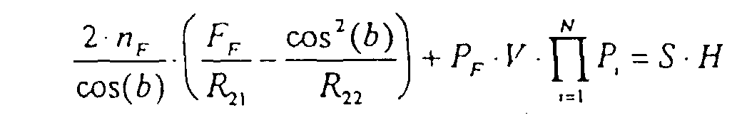
- astigmatism is, in accordance with the invention, eliminated in one point on the focal surface i.e. the sensitive surface 161, if the data of the optical components of the mounting satisfy the following equation
- equation (25) shall be applied with P F ⁇ F F ⁇ n F ⁇ 1.
- the equation (25) shall be applied with the quantity n F denoting the refractive index for the material that said prism is manufactured of.
- the quantity P F shall be calculated from equation ,(22) with the index i, replaced by the index F, that refers to the said prism.
- the quantities ⁇ F , A F , ⁇ ' F and ⁇ F are to be used instead of ⁇ i , A i , ⁇ ' i and ⁇ i .
- the quantity F F shall be calculated from equation (24') with A i , ⁇ ' i and ⁇ i replaced by the quantities A F , ⁇ ' F and ⁇ F .
- the index i in the sum and the products refer to those prismatic components that are separate from the imaging optical components.
- the apparatus, according to the invention is applied with two prismatic components 131 and 132 only, both integrated with each of the imaging optical components 12 and 15, shall the sum in the equation (25) have the numerical value 0 (zero) and the products in said equation have the numerical value 1 (one).
- Equation (25), or alternatively (26), is used according to the invention, together with for instance equations (18) and (21), in order to simultaneously achieve both a substantially uniform distribution of the order spectra and an elimination or reduction of the astigmatic aberration.
- the quantities for the prismatic components are thus determined through the equations (18) and (21), while for instance, the positioning of the entrance aperture is determined through the solution of the equation (25) alternatively the equation (26), in relation to the quantity r.
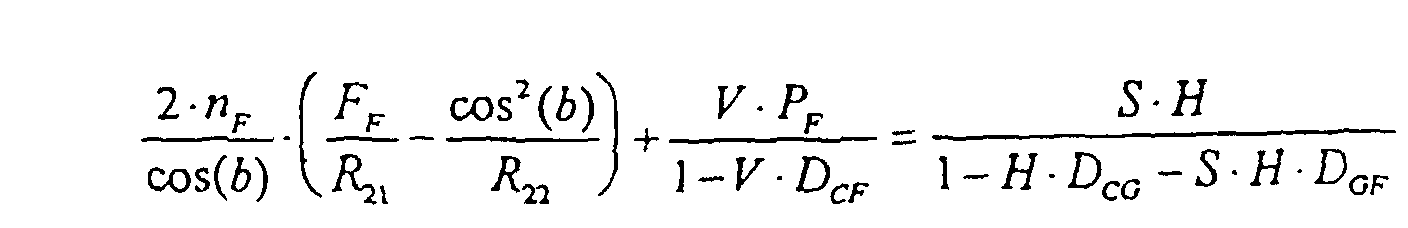
- Equation (25) alternatively (26) can also be applied in an approximated form valid when some or all of the inter component distances D CG , D PF or D GF can be neglected, meaning that these quantities can be used in equation (25) alternatively (26) with the numerical value 0 (zero).
- equations (25) and (26) are simplified to the following and respectively.
- Equation (25') alternatively (26') in stead of equation (25) alternatively (26), or obvious simplifications, or generalisations of these equations, is included in the invention, whenever such use is feasible technically. Equation (25') alternatively (26') shall be applied with the substitutions described for the cases for which equation (25) alternately (26) are valid.
- equation (25') alternatively (26') can be used when elimination of astigmatism is realised with the entrance aperture placed on such a distance r from the first imaging optical component 12, that the ray bundle of a given wavelength between said component and the second imaging optical component 15 is only slightly divergent or convergent.
- the prismatic components have been integrated with on or both of the imaging optical components, in such a way, as shown in Fig. 4.
- the reflecting surface has been ground and polished on the backside of each prism, that thus has been made reflecting.
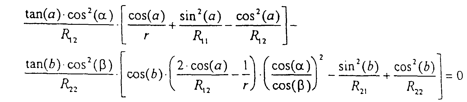
- Coma can be reduced or substantially eliminated by implementing another mathematical relations between the quantities of the spectral apparatus, according to the invention, to be valid.
- said mathematical relation reads
- Equations (27) and (28) are applied, according to the invention, together with the equations (18), (21) and (25) alternatively (26), in order to further improve the quality of the stigmatic image, and simultaneously achieve a substantially uniform distribution of the order spectra, obtained through the invention.
- equation (27) alternatively (28) can be used in a modified form as a result of simplifications, generalisations or approximations obvious to the professional.
- a spectral detector 1 for a pre-chosen detector unit 16, for instance a CCD-sensor, one has to start from certain initial technical requirements, put by the dimensions of the light sensitive surface 161 of the detector unit 16 and the application of the spectral detector. Most often the light sensitive surface 161 of the detector unit has a rectangular shape with a known width denoted by D s and a known height denoted by H. The latter quantity is included in the choice of the technical parameters of the prismatic components, according to the invention, based of the equations (18) and (21) alternatively (18') and (21').
- the spectral detector 1 for a desired and thus a pre-determined wavelength range, stretching from ⁇ min to ⁇ max .
- the application that the spectral detector is intended for puts demands on the so called spectral resolution R r (equation (6)).
- the corresponding wavelength resolution ⁇ can be calculated from the linear dispersion according to the equation (5), that thus related ⁇ to the corresponding linear quantity ⁇ l on the sensitive surface 161.
- This quantity ⁇ l is also pre-determined, because it is related to the resolving capability of the sensor used as detector unit 16.
- ⁇ l is in general a multiple of the width of an image element or a so called pixel.
- a common choice for ⁇ l is for instance 3 pixel widths.
- the product R r ⁇ l is also a constant characteristic of said basic design of the said detector 1.
- the expressions above contain the quantity m min that denote the spectral order of the longest wavelength ⁇ max , and the quantity ( ⁇ - ⁇ ) being the angle between the facet normal of the grooves of the diffraction grating and the direction of the incident radiation.
- the latter quantity ( ⁇ - ⁇ ) takes in practical mountings the value from -15 to +15 degrees.
- the first expression (equation (30)) shall be applied so that the quantities it contains, for instance R r , are adjusted so that the lowest order m min becomes an integer.
- the blaze angle ⁇ can be calculated from the second equations (31) and consequently the grating constant d from the third equation (32).
Landscapes
- Physics & Mathematics (AREA)
- Spectroscopy & Molecular Physics (AREA)
- General Physics & Mathematics (AREA)
- Spectrometry And Color Measurement (AREA)
- Investigating Or Analysing Materials By Optical Means (AREA)
- Lenses (AREA)
Claims (39)
- Dispositif d'analyse spectrale d'un rayonnement optique provenant d'une source de lumière, comprenant un détecteur spectral (1) avec une ouverture d'entrée (10) pour le rayonnement provenant de la source de lumière, un premier composant optique d'imagerie (12), un réseau de diffraction (14) pour disperser en longueur d'onde du rayonnement, des moyens de tri d'ordre pour séparer les ordres spectraux du réseau de diffraction, lesquels moyens dispersent le rayonnement d'une direction sensiblement orthogonale à la direction de dispersion du réseau de diffraction, un deuxième composant optique d'imagerie (15) et une unité de détection (16) pour enregistrer le spectre de la source de lumière, divisée en spectres d'ordre par lesdits moyens de tri d'ordre, caractérisé en ce que lesdits moyens de tri d'ordre comprennent au moins deux composants optiques réfractants (131) et (132) fabriqués dans des matériaux différents, lesquels composants sont agencés, avec le réseau de diffraction et les composants optiques d'imagerie (12, 15) pour co-agir afin de produire une distribution sensiblement uniforme desdits spectres d'ordre sur l'unité de détection (16) enregistrant le spectre simultanément.
- Dispositif selon la revendication 1, caractérisé en ce que lesdits composants optiques réfractants (131, 132) sont agencés, avec ledit réseau diffractant et lesdits composants optiques d'imagerie (12, 15) pour co-agir afin de produire une image sensiblement stigmatique de l'ouverture d'entrée (10) en au moins un point sur l'unité de détection (16).
- Dispositif selon la revendication 1 ou 2, caractérisé en ce que lesdits composants optiques d'imagerie (12, 15) sont des miroirs ayant des surfaces de forme concave.
- Dispositif selon l'une quelconque des revendications 1 à 3, caractérisé en ce que lesdits composants optiques réfractants (131, 132) ont une forme prismatique et sont agencés en sorte que la dispersion en longueur d'onde d'au moins un composant soit opposée à celle de l'autre.
- Dispositif selon la revendication 1 à 4, caractérisé par au moins un autre composant prismatique agencé sur la trajectoire lumineuse comprise entre ledit premier composant optique d'imagerie (12) et ledit deuxième composant optique d'imagerie (15).
- Dispositif selon l'une quelconque des revendications précédentes, caractérisé en ce que ladite co-action afin de produire une distribution sensiblement uniforme desdits spectres d'ordre et une image sensiblement stigmatique est atteinte en partie par un positionnement de l'ouverture d'entrée (10) par rapport au premier composant d'imagerie (12), en partie par le choix des propriétés optiques desdits composants prismatiques.
- Dispositif selon l'une quelconque des revendications 3 à 5, caractérisé en ce que lesdits miroirs à surfaces de forme concave sont montés en sorte que les plans de réflexion de ces deux miroirs, c'est-à-dire les plans contenant le rayon réfléchi au point central de la surface du miroir, à la fois avant et après ladite réflexion, sont sensiblement orthogonaux à la direction définie par la dispersion en longueur d'onde dudit réseau de diffraction au niveau des miroirs, de sorte que, pour obtenir l'image stigmatique, la relation suivante est satisfaite par les quantités décrivant les composants du détecteur spectraloù
 et où
et où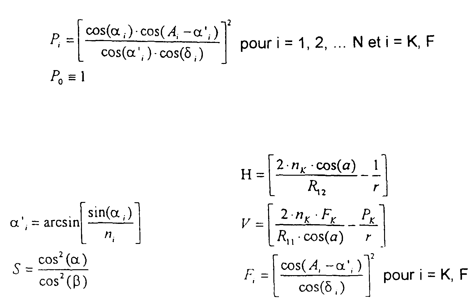
- R21=
- le rayon de courbure de la courbe d'intersection entre la surface du deuxième composant d'imagerie (15) et son plan de réflexion,
- R22 =
- le rayon de courbure de la courbe d'intersection entre la surface du deuxième composant d'imagerie (15) et le plan passant par le centre de la surface orthogonalement au plan de réflexion,
- b =
- l'angle d'inclinaison dudit composant d'imagerie, c'est-à-dire l'angle entre la direction d'un rayon passant par le centre de la surface du composant et la normale à la surface passant par le centre,
- DCG =
- la trajectoire de rayon totale d'un rayon central allant du premier composant optique d'imagerie (12) au réseau de diffraction (14),
- i =
- indice désignant le i-ème composant prismatique dans l'ordre défini par le rayonnement quand il passe du premier (12) au deuxième (15) composant optique d'imagerie, où l'indice i = K signifie que la quantité se rapporte au premier composant prismatique, avec ledit premier composant d'imagerie (12) intégré; l'indice i = F signifie que la quantité se rapporte au dernier composant prismatique, avec ledit deuxième composant d'imagerie intégré ; l'indice i=1, 2,... N signifie que la quantité se rapporte aux composants prismatiques positionnés entre lesdits composants d'imagerie (12, 15),
- Di =
- la trajectoire de rayon totale d'un rayon central allant du i-ème composant prismatique au deuxième composant optique d'imagerie (15),
- DGF =
- la trajectoire de rayon totale d'un rayon central allant du réseau de diffraction (14) au deuxième composant optique d'imagerie (15),
- DCF=
- la trajectoire de rayon totale d'un rayon central allant du premier composant optique d'imagerie (12) au deuxième composant optique d'imagerie (15),
- N =
- le nombre de fois que le rayonnement traverse les composants prismatiques de l'unité de tri d'ordres (13) qui sont séparés des composants optiques d'imagerie (12, 15),
- ni =
- l'indice de réfraction du matériau optique du i-ème composant prismatique,
- αi =
- l'angle d'incidence, c'est-à-dire l'angle entre la direction d'un rayon incident et la normale à la première surface réfractante desdits i-èmes composants prismatiques, où αi doit avoir un signe positif si ledit rayon est incident sur le côté opposé à ladite normale, par rapport au côté que définit le bord du prisme
- δi =
- l'angle entre la direction d'un rayon qui sort après réfraction dans la deuxième surface réfractante dudit i-ème composant prismatique, et la normale à ladite surface, δi ayant un signe positif si ledit rayon émerge du côté opposé à ladite normale, par rapport au côté que définit le bord du prisme
- Ai =
- l'angle de réfraction dudit i-ème composant prismatique, c'est-à-dire l'angle entre les surfaces optiques dudit composant si les deux surfaces sont réfractantes, et deux fois la valeur dudit angle si l'une des surfaces est réfléchissante,
- α =
- l'angle entre la direction du rayon incident et la normale à la surface de diffraction,
- β =
- l'angle de diffraction, c'est-à-dire l'angle entre la direction du rayon sortant après diffraction et la normale à la surface de diffraction,
- r =
- la distance entre l'ouverture d'entrée (10) et le premier composant optique d'imagerie (12),
- R11 =
- le rayon de courbure de la courbe d'intersection entre la surface du premier composant d'imagerie (12) et son plan de réflexion,
- R12 =
- le rayon de courbure de la courbe d'intersection entre la surface du premier composant d'imagerie (12) et le plan passant par le centre de la surface orthogonalement au plan de réflexion,
- a =
- l'angle d'inclinaison dudit composant d'imagerie, c'est-à-dire l'angle entre la direction d'un rayon passant par le centre de la surface du composant et la normale à la surface passant par le centre.
- Dispositif selon la revendication 7, caractérisé en ce que ladite relation mathématique pour obtenir une imagerie stigmatique est appliquée sous la forme approchée suivante :
- Dispositif selon la revendication 7 ou 8, caractérisé en ce que tous lesdits composants prismatiques (131, 132,...) sont montés séparément desdits deux composants d'imagerie (12, 15), de sorte que lesdites relations mathématiques sont appliquées avec nK=nF=FK=FF=PK=PF=1.
- Dispositif selon la revendication 7 ou 8, caractérisé en ce que le premier composant prismatique (131) est intégré audit premier composant d'imagerie (12), tandis que les autres composants prismatiques (132,133... ) sont montés séparément dudit deuxième composant d'imagerie (15), de sorte que lesdites relations mathématiques sont appliquées avec nF=FF=PF=1.
- Dispositif selon la revendication 7 ou 8, caractérisé en ce que le dernier composant prismatique est intégré audit deuxième composant d'imagerie (15), tandis que les autres composants prismatiques (131, 132,... ) sont montés séparément dudit premier composant d'imagerie (12), de sorte que lesdites relations mathématiques sont appliquées avec nK=FK=PK=1.
- Dispositif selon la revendication 7, caractérisé en ce que le détecteur spectral (1) contient deux composants prismatiques (131, 132), le premier (131) étant intégré au premier composant d'imagerie (12) et le deuxième composant prismatique (132) étant intégré au deuxième composant d'imagerie (15), de sorte que lesdites relations mathématiques pour obtenir une imagerie stigmatique sont appliquées sous la forme suivante :
- Dispositif selon l'une des revendications 3 à 6, caractérisé en ce que lesdits miroirs à surfaces de forme concave sont montés en sorte que les plans de réflexion de ces miroirs, c'est-à-dire les plans contenant le rayon réfléchi au point central de la surface du miroir, tant avant et après réflexion, sont sensiblement parallèles à la direction définie au niveau desdits miroirs par la dispersion en longueur d'onde dudit réseau de diffraction, de sorte que, pour obtenir l'image stigmatique, la relation suivante est satisfaite par les quantités décrivant les composants du détecteur spectraloù

 et où
et où
- R21 =
- le rayon de courbure de la courbe d'intersection entre la surface du deuxième composant d'imagerie (15) et le plan passant par le centre de la surface orthogonalement au plan de réflexion,
- R22 =
- le rayon de courbure de la courbe d'intersection entre la surface du deuxième composant d'imagerie (15) et le plan passant par le centre de la surface orthogonalement au plan de réflexion,
- b =
- l'angle d'inclinaison dudit composant d'imagerie, c'est-à-dire l'angle entre la direction d'un rayon passant par le centre de la surface du composant et la normale à la surface passant par ledit centre,
- DCG =
- la trajectoire de rayon totale d'un rayon central allant du premier composant optique d'imagerie (12) au réseau de diffraction (14),
- DGF =
- la trajectoire de rayon totale d'un rayon central allant du réseau de diffraction (14) au deuxième composant optique d'imagerie (15),
- DCF =
- la trajectoire de rayon totale d'un rayon central allant du premier composant optique d'imagerie (12) au deuxième composant optique d'imagerie (15),
- i =
- indice désignant le i-ème composant prismatique dans l'ordre défini par le rayonnement quand il passe du premier (12) au deuxième (15) composant optique d'imagerie, où l'indice i = K signifie que la quantité se rapporte au premier composant prismatique, avec ledit premier composant d'imagerie (12) intégré ; l'indice i = F signifie que la quantité se rapporte au dernier composant prismatique, avec ledit deuxième composant d'imagerie intégré ; l'indice i=1, 2,... N signifie que la quantité se rapporte aux composants prismatiques positionnés entre lesdits composants d'imagerie (12, 15),
- Di =
- la trajectoire de rayon totale d'un rayon central allant du i-ème composant prismatique au deuxième composant optique d'imagerie (15),
- N =
- le nombre de fois que le rayonnement traverse les composants prismatiques de l'unité de tri d'ordres (13) qui sont séparés des composants optiques d'imagerie (12, 15),
- ni =
- l'indice de réfraction du matériau optique du i-ème composant prismatique,
- αi =
- l'angle d'incidence, c'est-à-dire l'angle entre la direction d'un rayon incident et la normale à la première surface réfractante desdits i-èmes composants prismatiques, où αi doit avoir un signe positif si ledit rayon est incident sur le côté opposé à ladite normale, par rapport au côté que définit le bord du prisme
- δi =
- l'angle entre la direction d'un rayon qui sort après réfraction dans la deuxième surface réfractante dudit i-ème composant prismatique, et la normale à ladite surface, δi ayant un signe positif si ledit rayon émerge du côté opposé à ladite normale, par rapport au côté que définit le bord du prisme
- Ai =
- l'angle de réfraction dudit i-ème composant prismatique, c'est-à-dire l'angle entre les surfaces optiques dudit composant si les deux surfaces sont réfractantes, et deux fois la valeur dudit angle si l'une des surfaces est réfléchissante,
- α =
- l'angle entre la direction du rayon incident et la normale à la surface de diffraction,
- β =
- l'angle de diffraction, c'est-à-dire l'angle entre la direction du rayon sortant après diffraction et la normale à la surface de diffraction,
- r =
- la distance entre l'ouverture d'entrée (10) et le premier composant optique d'imagerie (12),
- R11 =
- le rayon de courbure de la courbe d'intersection entre la surface du premier composant d'imagerie (12) et son plan de réflexion,
- R12 =
- le rayon de courbure de la courbe d'intersection entre la surface du premier composant d'imagerie (12) et le plan passant par le centre de la surface orthogonalement au plan de réflexion,
- a =
- l'angle d'inclinaison dudit composant d'imagerie, c'est-à-dire l'angle entre la direction d'un rayon passant par le centre de la surface du composant et la normale à la surface passant par ledit centre.
- Dispositif selon la revendication 13, caractérisé en ce que ladite relation mathématique pour obtenir une imagerie stigmatique est appliquée sous la forme approchée suivante :

- Dispositif selon l'une quelconque des revendications 1 à 14, caractérisé en ce que, pour obtenir une distribution sensiblement uniforme desdits spectres d'ordre sur ledit détecteur (16), les valeurs des composants réfractants (131, 132,... ) de l'unité de tri d'ordres (13) sont choisies en sorte que la relation mathématique suivante soit satisfaite :
- δN =
- l'angle entre la direction d'un rayon qui sorte après réfraction dans la deuxième surface réfractante du N-ème composant prismatique et la normale à ladite surface, le N-ème composant prismatique étant le dernier des composants prismatiques dans l'ordre défini par la trajectoire de rayon,
- λa =
- une longueur d'onde choisie arbitrairement, à laquelle est calculée la première dérivée de l'équation mathématique,
- λb =
- une longueur d'onde choisie de manière similaire, différente de λa, à laquelle est calculée la deuxième dérivée de l'équation mathématique.
- Dispositif selon la revendication 15, caractérisé en ce que les longueurs d'onde λa et λb sont choisies pour coïncider approximativement avec les longueurs d'ondes auxquelles un seul composant prismatique, servant d'unité de tri d'ordre (13), conduit à la plus grande et à la plus petite distance entre lesdits spectres d'ordre sur ladite unité de détection (16), respectivement.
- Dispositif selon l'une quelconque des revendications 1 à 16, caractérisé en ce que, pour utiliser pleinement la hauteur de la surface sensible (161) de l'unité de détection (16), la relation mathématique suivante est satisfaite :
- λmax =
- la plus grande longueur d'onde dans la plage de longueurs d'onde du détecteur spectral (1),
- λmin =
- la plus courte longueur d'onde dans la plage de longueurs d'onde du détecteur spectral (1),
- δN(λmax) :
- ledit angle de sortie pour un rayon de longueur d'onde λmax,
- δN(λmin) :
- ledit angle de sortie pour un rayon de longueur d'onde λmin,
- H =
- la hauteur de la surface sensible (161) dans la direction orthogonale à la direction correspondant à la direction de dispersion du réseau de diffraction sur ladite surface,
- h =
- la hauteur de l'image de l'ouverture d'entrée (10) sur la surface sensible (161) dans la direction orthogonale à la direction correspondant à la direction de dispersion du réseau de diffraction sur ladite surface,
- fv eff =
- la distance focale effective utilisée pour calculer la taille de l'image sur la surface focale, dans la direction correspondant à la direction de dispersion de l'unité de tri d'ordres (13) sur ladite surface.
- Dispositif selon l'une quelconque des revendications 15 à 17, caractérisé en ce que ledit dernier composant prismatique est intégré audit deuxième composant d'imagerie (15), de sorte que lesdites relations mathématiques sont appliquées avec ledit angle de sortie δN remplacé par l'angle de sortie correspondant δF, calculé pour ledit dernier composant prismatique.
- Dispositif selon l'une quelconque des revendications 15 à 18, caractérisé en ce que ledit angle de sortie est calculé à partir de la relation mathématique de récursion suivante
- A'i+1 =
- l'angle entre les surfaces optiques des i-ème et (i+1)-ème prismes adjacents l'un à l'autre sur la trajectoire du rayon,
- ki+1 =
- 1 quand le bord dudit (i+1)-ème prisme est tourné dans la même direction que celui du i-ème prisme,
- ki+1 =
- 2 quand le bord dudit (i+1)-ème prisme est tourné dans la direction opposée à celui du i-ème prisme.
- Dispositif selon la revendication 19, caractérisé en ce que la relation mathématique de récursion est appliquée sous la forme approchée suivante :
- Dispositif selon l'une quelconque des revendications 7 à 20, caractérisé en ce que lesdits plans de réflexion des deux surfaces de miroir (12, 15) ayant des surfaces de forme concave sont sensiblement orthogonaux à la direction définie au niveau des miroirs par la dispersion en longueur d'onde dudit réseau de diffraction (14), et en ce que lesdits composants réfractants (131, 132) sont montés séparément desdits miroirs (12, 15), de sorte que, pour la réduction de l'aberration en coma de l'image sur la surface sensible (161) de l'unité de détection (16), la relation mathématique suivante entre les quantités décrivant les composants du détecteur spectral (1) est satisfaite
- Dispositif selon l'une quelconque des revendications 7 à 20, caractérisé en ce que lesdits plans de réflexion des deux surfaces de miroir (12, 15) ayant des surfaces de forme concave sont sensiblement orthogonaux à la direction définie au niveau des miroirs par la dispersion en longueur d'onde dudit réseau de diffraction (14), et en ce que lesdits composants réfractants (131, 132) sont intégrés à chacun desdits miroirs (12, 15), de sorte que, pour la réduction de l'aberration en coma de l'image sur la surface sensible (161) de l'unité de détection (16), la relation mathématique suivante entre les quantités décrivant les composants du détecteur spectral (1) est satisfaite
- Dispositif selon la revendication 22, caractérisé en ce que le premier composant prismatique (131) est intégré audit premier composant d'imagerie (12), tandis que les autres composants prismatiques (132, 133,... ) sont montés séparément dudit deuxième composant d'imagerie (15), de sorte que ladite relation mathématique est appliquée avec nF=1 et αF=α'F.
- Dispositif selon la revendication 22, caractérisé en ce que le dernier composant prismatique est intégré audit deuxième composant d'imagerie (15), tandis que les autres composants prismatiques (131, 133,... ) sont montés séparément dudit premier composant d'imagerie (12), de sorte que ladite relation mathématique est appliquée avec nK=1 et δK=AK - α'K.
- Dispositif selon l'une quelconque des revendications 7 à 20, caractérisé en ce que lesdits plans de réflexion pour lesdites deux surfaces de miroir (12, 15) ayant des surfaces de forme concave sont sensiblement parallèles à la direction définie au niveau des miroirs par la dispersion en longueur d'onde dudit réseau de diffraction (14), de sorte que, pour la réduction de l'aberration en coma de l'image sur la surface sensible (161) de l'unité de détection (16), la relation mathématique suivante entre les quantités décrivant les composants du détecteur spectral (1) est satisfaite
- Dispositif selon l'une quelconque des revendications 1 à 25, caractérisé en ce qu'à partir de ladite longueur d'onde maximale (λmax) du détecteur spectral (1), de son pouvoir de résolution spectrale (Rr), de la distance (Δl) sur la surface sensible (161) correspondant au pouvoir de résolution spectrale et, enfin, de ladite largeur (Ds) de ladite surface sensible (161) dans la direction que la dispersion dudit réseau définit sur ladite surface (161), on obtient une utilisation optimale de ladite surface sensible (161) en choisissant les principaux paramètres du détecteur spectral (1), de sorte que les relations mathématiques suivantes soient satisfaites
- mmin =
- l'ordre spectral dans lequel est diffractée la plus courte longueur d'onde λmin du détecteur spectral,
- =
- l'angle de blaze, c'est-à-dire l'angle entre la normale à la surface du réseau et la normale aux facettes des stries, c'est-à-dire les surfaces réfléchissantes des stries sur la surface du réseau,
- d =
- la distance entre les lignes ou stries sur la surface du réseau,
- α =
- l'angle entre la direction du rayonnement incident et la normale à la surface du réseau,
- fh eff =
- la distance focale effective utilisée pour calculer la taille de l'image sur la surface focale (161), dans la direction correspondant à la direction de la dispersion du réseau sur ladite surface.
- Dispositif selon l'une quelconque des revendications 17 à 26, caractérisé en ce que lesdits plans de réflexion sur lesdites deux surfaces de miroir (12, 15) sont sensiblement orthogonaux à la direction définie au niveau des miroirs par la dispersion en longueur d'onde dudit réseau de diffraction (14), de sorte que les valeurs des distances focales effectives fv eff et fh eff dans lesdites relations mathématiques sont choisies de telle manière que les relations mathématiques approchées suivantes soient satisfaites :
- Dispositif selon l'une quelconque des revendications 17 à 26, caractérisé en ce que lesdits plans de réflexion sur lesdites deux surfaces de miroir (12, 15) sont sensiblement parallèles à la direction définie au niveau des miroirs par la dispersion en longueur d'onde dudit réseau de diffraction (14), de sorte que les valeurs des distances focales effectives fv eff et fh eff dans lesdites relations mathématiques sont choisies de telle manière que les relations mathématiques approchées suivantes soient satisfaites :
- Dispositif selon l'une quelconque des revendications 7 à 28, caractérisé en ce que ledit premier composant optique (12) est un miroir concave à surface de forme sphérique, de sorte que lesdites relations mathématiques sont appliquées avec R12=R11=R1, la notation R1 désignant le rayon de courbure de ladite surface sphérique.
- Dispositif selon l'une quelconque des revendications 7 à 29, caractérisé en ce que ledit deuxième composant optique (15) est un miroir concave à surface de forme sphérique, de sorte que lesdites relations mathématiques sont appliquées avec R22=R21=R2, la notation R2 désignant le rayon de courbure de ladite surface sphérique.
- Dispositif selon l'une quelconque des revendications 1 à 30, caractérisé en ce qu'au moins deux des composants prismatiques ont une surface optique commune, c'est-à-dire que les surfaces desdits prismes sont jointes pour avoir un contact optique l'une avec l'autre.
- Dispositif selon l'une quelconque des revendications 1 à 31, caractérisé en ce qu'au moins l'un des composants prismatiques a une surface optique qui est réfléchissante.
- Dispositif selon l'une quelconque des revendications 1 à 32, caractérisé en ce qu'au moins l'un desdits composants prismatiques est fabriqué à partir d'un matériau optique à base de fluorure de lithium (LiF) et en ce qu'un autre composant prismatique à dispersion en longueur d'onde contraire est fabriqué à partir d'un matériau optique choisi parmi le groupe qui comprend le fluorure de baryum (BaF2) et le quartz fondu.
- Dispositif selon l'une quelconque des revendications 1 à 32, caractérisé en ce qu'au moins l'un desdits composants prismatiques est fabriqué à partir d'un matériau optique portant la désignation LaK 31, ou d'un matériau présentant des propriétés de dispersion similaires, et en ce qu'un autre composant prismatique à dispersion en longueur d'onde contraire est fabriqué à partir du matériau optique appelé SF 18, ou d'un matériau présentant des propriétés de dispersion similaires.
- Dispositif selon l'une quelconque des revendications 1 à 34, caractérisé en ce que ladite source de lumière (11) est choisie parmi le groupe de sources de lumière électriques qui comprend des décharges d'arc, des étincelles, des flammes et des décharges luminescentes.
- Dispositif selon l'une quelconque des revendications 1 à 34, caractérisé en ce que ladite source de lumière (11) est composée d'une lampe choisie parmi le groupe de lampes comprenant des lampes halogènes, à arc et à flash, et une enceinte pour des échantillons liquides ou gazeux, de sorte que l'unité de détection (1) enregistre l'absorption spectrale ou la fluorescence spectrale dudit échantillon.
- Dispositif selon l'une quelconque des revendications 1 à 34, caractérisé en ce que ladite source de lumière (11) est un plasma qui a été généré soit par des moyens électriques, soit par de la lumière laser.
- Dispositif selon l'une quelconque des revendications 1 à 34, caractérisé en ce que ladite source de lumière (11) est le soleil directement, ou sa lumière diffusée.
- Dispositif selon l'une quelconque des revendications 1 à 34, caractérisé en ce que ladite source de lumière (11) est un procédé de combustion choisi parmi le groupe comprenant les flammes, les explosions et les incendies impliquant des gaz, des liquides et des solides.
Applications Claiming Priority (3)
| Application Number | Priority Date | Filing Date | Title |
|---|---|---|---|
| SE9401669 | 1994-05-16 | ||
| SE9401669A SE502809C2 (sv) | 1994-05-16 | 1994-05-16 | Anordning för spektralanalys av optisk ljuskälla med bilddetektion och uppdelning av spektralordningar |
| PCT/SE1995/000543 WO1995031703A1 (fr) | 1994-05-16 | 1995-05-15 | Appareil pour effectuer une analyse spectrale d'une source de lumiere optique par detection d'image et separation d'ordres spectraux |
Publications (2)
| Publication Number | Publication Date |
|---|---|
| EP0764262A1 EP0764262A1 (fr) | 1997-03-26 |
| EP0764262B1 true EP0764262B1 (fr) | 2000-08-02 |
Family
ID=20394006
Family Applications (1)
| Application Number | Title | Priority Date | Filing Date |
|---|---|---|---|
| EP95919724A Expired - Lifetime EP0764262B1 (fr) | 1994-05-16 | 1995-05-15 | Appareil pour effectuer une analyse spectrale d'une source de lumiere optique par detection d'image et separation d'ordres spectraux speciaux |
Country Status (8)
| Country | Link |
|---|---|
| US (1) | US5859702A (fr) |
| EP (1) | EP0764262B1 (fr) |
| AT (1) | ATE195179T1 (fr) |
| AU (1) | AU2542495A (fr) |
| DE (1) | DE69518244T2 (fr) |
| ES (1) | ES2151064T3 (fr) |
| SE (1) | SE502809C2 (fr) |
| WO (1) | WO1995031703A1 (fr) |
Families Citing this family (21)
| Publication number | Priority date | Publication date | Assignee | Title |
|---|---|---|---|---|
| DE19537949A1 (de) * | 1995-10-12 | 1997-04-17 | Zeiss Carl Fa | Spektralapparat zum konzentrischen Typ mit FEry-Prisma |
| US5675411A (en) * | 1996-05-10 | 1997-10-07 | General Atomics | Broad-band spectrometer with high resolution |
| CA2330311A1 (fr) | 1998-04-29 | 1999-11-04 | American Holographic, Inc. | Spectrometre concentrique a correction |
| US6603549B2 (en) | 2000-02-25 | 2003-08-05 | Cymer, Inc. | Convolution method for measuring laser bandwidth |
| US6406153B1 (en) | 2000-11-10 | 2002-06-18 | Paul R. Stremple | Spectral dispersion device |
| US6538737B2 (en) * | 2001-01-29 | 2003-03-25 | Cymer, Inc. | High resolution etalon-grating spectrometer |
| FR2857746B1 (fr) * | 2003-07-16 | 2005-11-25 | Agence Spatiale Europeenne | Spectrometre optique miniaturise a haute resolution |
| US7564552B2 (en) * | 2004-05-14 | 2009-07-21 | Kla-Tencor Technologies Corp. | Systems and methods for measurement of a specimen with vacuum ultraviolet light |
| US7359052B2 (en) * | 2004-05-14 | 2008-04-15 | Kla-Tencor Technologies Corp. | Systems and methods for measurement of a specimen with vacuum ultraviolet light |
| US20060023217A1 (en) * | 2004-05-28 | 2006-02-02 | Chemimage Corporation | Method and apparatus for producing a mosaic image |
| US7408641B1 (en) | 2005-02-14 | 2008-08-05 | Kla-Tencor Technologies Corp. | Measurement systems configured to perform measurements of a specimen and illumination subsystems configured to provide illumination for a measurement system |
| US7495761B2 (en) * | 2006-02-03 | 2009-02-24 | Foster-Miller, Inc. | Array detector coupled spectroanalytical system and graded blaze angle grating |
| TWI345050B (en) * | 2007-08-03 | 2011-07-11 | Oto Photonics Inc | Optical system and method of manufacturing the same |
| US9146155B2 (en) * | 2007-03-15 | 2015-09-29 | Oto Photonics, Inc. | Optical system and manufacturing method thereof |
| DE102008007783A1 (de) * | 2008-02-06 | 2009-08-13 | Erwin Kayser-Threde Gmbh | Abbildendes Spektrometer, insbesondere für die Fernerkundung |
| US20090273840A1 (en) | 2008-05-02 | 2009-11-05 | Mclaughlin Sheldon | Wavelength dispersing device |
| DE102009003413B4 (de) | 2009-01-30 | 2022-01-20 | Leibniz - Institut Für Analytische Wissenschaften - Isas - E.V. | Echelle-Spektrometeranordnung mit interner Vordispersion |
| WO2012142980A1 (fr) | 2011-04-19 | 2012-10-26 | 20Ten Sports, S.R.O. | Embout de manche multifonctionnel |
| US20170010153A1 (en) | 2014-01-30 | 2017-01-12 | Horiba Instruments Incorporated | Spectroscopic mapping system and method |
| CN108738335B (zh) | 2016-01-14 | 2021-03-16 | 耶拿分析仪器股份公司 | 具有二维光谱的光谱仪 |
| TWI715599B (zh) | 2016-07-12 | 2021-01-11 | 台灣超微光學股份有限公司 | 光譜儀模組及其製作方法 |
Family Cites Families (3)
| Publication number | Priority date | Publication date | Assignee | Title |
|---|---|---|---|---|
| SE359648B (fr) * | 1972-03-17 | 1973-09-03 | N Danielsson | |
| FI75047C (sv) * | 1982-05-11 | 1988-04-11 | Scanoptics Oy | Anordning för utförande av spektralanalys. |
| US5139335A (en) * | 1990-08-24 | 1992-08-18 | Sets, Inc. | Holographic grating imaging spectrometer |
-
1994
- 1994-05-16 SE SE9401669A patent/SE502809C2/sv unknown
-
1995
- 1995-05-15 DE DE69518244T patent/DE69518244T2/de not_active Expired - Fee Related
- 1995-05-15 WO PCT/SE1995/000543 patent/WO1995031703A1/fr not_active Ceased
- 1995-05-15 EP EP95919724A patent/EP0764262B1/fr not_active Expired - Lifetime
- 1995-05-15 ES ES95919724T patent/ES2151064T3/es not_active Expired - Lifetime
- 1995-05-15 US US08/737,339 patent/US5859702A/en not_active Expired - Lifetime
- 1995-05-15 AT AT95919724T patent/ATE195179T1/de not_active IP Right Cessation
- 1995-05-15 AU AU25424/95A patent/AU2542495A/en not_active Abandoned
Also Published As
| Publication number | Publication date |
|---|---|
| AU2542495A (en) | 1995-12-05 |
| ATE195179T1 (de) | 2000-08-15 |
| US5859702A (en) | 1999-01-12 |
| EP0764262A1 (fr) | 1997-03-26 |
| SE502809C2 (sv) | 1996-01-22 |
| WO1995031703A1 (fr) | 1995-11-23 |
| SE9401669L (sv) | 1995-11-17 |
| DE69518244D1 (de) | 2000-09-07 |
| DE69518244T2 (de) | 2001-03-29 |
| ES2151064T3 (es) | 2000-12-16 |
| SE9401669D0 (sv) | 1994-05-16 |
Similar Documents
| Publication | Publication Date | Title |
|---|---|---|
| EP0764262B1 (fr) | Appareil pour effectuer une analyse spectrale d'une source de lumiere optique par detection d'image et separation d'ordres spectraux speciaux | |
| US7936455B2 (en) | Three mirror anastigmat spectrograph | |
| US7936454B2 (en) | Three mirror anastigmat spectrograph | |
| US7106440B2 (en) | Refractive-diffractive spectrometer | |
| US6862092B1 (en) | Spectrometer | |
| US5644396A (en) | Spectrograph with low focal ratio | |
| EP0746746B1 (fr) | Analyse multispectrale d'une image | |
| US4060327A (en) | Wide band grating spectrometer | |
| EP0602992B1 (fr) | Une combinaison d'un réseau de diffraction et d'un prisme | |
| US4634276A (en) | Slit imaging system using two concave mirrors | |
| US7116418B2 (en) | Spectral imaging apparatus and methods | |
| US3704951A (en) | S light cell for increasing the intensity level of raman light emission from a sample | |
| USRE42822E1 (en) | Modified concentric spectrograph | |
| JP5517621B2 (ja) | 高感度スペクトル分析ユニット | |
| US6628383B1 (en) | Imaging spectrograph for multiorder spectroscopy | |
| US5189486A (en) | Echelle polychromator | |
| US20030142307A1 (en) | Dispersive spectrometer | |
| US5448351A (en) | Echelle polychromator | |
| WO2003023339A1 (fr) | Dispositif et procede permettant d'obtenir une image sensiblement droite a partir d'une image produite par un instrument de mesure | |
| US9677932B2 (en) | Field lens corrected three mirror anastigmat spectrograph | |
| Butler et al. | Nomenclature, symbols, units and their usage in spectrochemical analysis-IX. Instrumentation for the spectral dispersion and isolation of optical radiation (IUPAC Recommendations 1995) | |
| WO1990002928A1 (fr) | Spectrometre a formation d'image | |
| US7019833B2 (en) | Miniature optical spectrometer | |
| KR101884118B1 (ko) | 투과 회절 격자 기반 분광기 | |
| RU2069323C1 (ru) | Спектроскоп |
Legal Events
| Date | Code | Title | Description |
|---|---|---|---|
| PUAI | Public reference made under article 153(3) epc to a published international application that has entered the european phase |
Free format text: ORIGINAL CODE: 0009012 |
|
| 17P | Request for examination filed |
Effective date: 19961216 |
|
| AK | Designated contracting states |
Kind code of ref document: A1 Designated state(s): AT BE CH DE DK ES FR GB IE IT LI NL |
|
| GRAG | Despatch of communication of intention to grant |
Free format text: ORIGINAL CODE: EPIDOS AGRA |
|
| 17Q | First examination report despatched |
Effective date: 19991011 |
|
| GRAG | Despatch of communication of intention to grant |
Free format text: ORIGINAL CODE: EPIDOS AGRA |
|
| GRAH | Despatch of communication of intention to grant a patent |
Free format text: ORIGINAL CODE: EPIDOS IGRA |
|
| RAP1 | Party data changed (applicant data changed or rights of an application transferred) |
Owner name: MULTICHANNEL INSTRUMENTS AB |
|
| RIN1 | Information on inventor provided before grant (corrected) |
Inventor name: LINDBLOM, PETER |
|
| GRAH | Despatch of communication of intention to grant a patent |
Free format text: ORIGINAL CODE: EPIDOS IGRA |
|
| GRAA | (expected) grant |
Free format text: ORIGINAL CODE: 0009210 |
|
| AK | Designated contracting states |
Kind code of ref document: B1 Designated state(s): AT BE CH DE DK ES FR GB IE IT LI NL |
|
| REF | Corresponds to: |
Ref document number: 195179 Country of ref document: AT Date of ref document: 20000815 Kind code of ref document: T |
|
| REG | Reference to a national code |
Ref country code: CH Ref legal event code: EP |
|
| REG | Reference to a national code |
Ref country code: IE Ref legal event code: FG4D |
|
| REF | Corresponds to: |
Ref document number: 69518244 Country of ref document: DE Date of ref document: 20000907 |
|
| ITF | It: translation for a ep patent filed | ||
| PG25 | Lapsed in a contracting state [announced via postgrant information from national office to epo] |
Ref country code: DK Free format text: LAPSE BECAUSE OF FAILURE TO SUBMIT A TRANSLATION OF THE DESCRIPTION OR TO PAY THE FEE WITHIN THE PRESCRIBED TIME-LIMIT Effective date: 20001102 |
|
| ET | Fr: translation filed | ||
| REG | Reference to a national code |
Ref country code: CH Ref legal event code: NV Representative=s name: E. BLUM & CO. PATENTANWAELTE |
|
| REG | Reference to a national code |
Ref country code: ES Ref legal event code: FG2A Ref document number: 2151064 Country of ref document: ES Kind code of ref document: T3 |
|
| PG25 | Lapsed in a contracting state [announced via postgrant information from national office to epo] |
Ref country code: IE Free format text: LAPSE BECAUSE OF NON-PAYMENT OF DUE FEES Effective date: 20010515 |
|
| PLBE | No opposition filed within time limit |
Free format text: ORIGINAL CODE: 0009261 |
|
| STAA | Information on the status of an ep patent application or granted ep patent |
Free format text: STATUS: NO OPPOSITION FILED WITHIN TIME LIMIT |
|
| 26N | No opposition filed | ||
| REG | Reference to a national code |
Ref country code: GB Ref legal event code: IF02 |
|
| REG | Reference to a national code |
Ref country code: IE Ref legal event code: MM4A |
|
| PGFP | Annual fee paid to national office [announced via postgrant information from national office to epo] |
Ref country code: NL Payment date: 20020514 Year of fee payment: 8 |
|
| PGFP | Annual fee paid to national office [announced via postgrant information from national office to epo] |
Ref country code: ES Payment date: 20020516 Year of fee payment: 8 |
|
| PGFP | Annual fee paid to national office [announced via postgrant information from national office to epo] |
Ref country code: CH Payment date: 20020517 Year of fee payment: 8 Ref country code: BE Payment date: 20020517 Year of fee payment: 8 |
|
| PGFP | Annual fee paid to national office [announced via postgrant information from national office to epo] |
Ref country code: AT Payment date: 20020522 Year of fee payment: 8 |
|
| PG25 | Lapsed in a contracting state [announced via postgrant information from national office to epo] |
Ref country code: AT Free format text: LAPSE BECAUSE OF NON-PAYMENT OF DUE FEES Effective date: 20030515 |
|
| PG25 | Lapsed in a contracting state [announced via postgrant information from national office to epo] |
Ref country code: ES Free format text: LAPSE BECAUSE OF NON-PAYMENT OF DUE FEES Effective date: 20030516 |
|
| PG25 | Lapsed in a contracting state [announced via postgrant information from national office to epo] |
Ref country code: LI Free format text: LAPSE BECAUSE OF NON-PAYMENT OF DUE FEES Effective date: 20030531 Ref country code: CH Free format text: LAPSE BECAUSE OF NON-PAYMENT OF DUE FEES Effective date: 20030531 Ref country code: BE Free format text: LAPSE BECAUSE OF NON-PAYMENT OF DUE FEES Effective date: 20030531 |
|
| BERE | Be: lapsed |
Owner name: *MULTICHANNEL INSTRUMENTS A.B. Effective date: 20030531 |
|
| PG25 | Lapsed in a contracting state [announced via postgrant information from national office to epo] |
Ref country code: NL Free format text: LAPSE BECAUSE OF NON-PAYMENT OF DUE FEES Effective date: 20031201 |
|
| REG | Reference to a national code |
Ref country code: CH Ref legal event code: PL |
|
| NLV4 | Nl: lapsed or anulled due to non-payment of the annual fee |
Effective date: 20031201 |
|
| REG | Reference to a national code |
Ref country code: ES Ref legal event code: FD2A Effective date: 20030516 |
|
| PGFP | Annual fee paid to national office [announced via postgrant information from national office to epo] |
Ref country code: IT Payment date: 20060531 Year of fee payment: 12 |
|
| PGFP | Annual fee paid to national office [announced via postgrant information from national office to epo] |
Ref country code: DE Payment date: 20080717 Year of fee payment: 14 |
|
| PGFP | Annual fee paid to national office [announced via postgrant information from national office to epo] |
Ref country code: FR Payment date: 20080415 Year of fee payment: 14 |
|
| PGFP | Annual fee paid to national office [announced via postgrant information from national office to epo] |
Ref country code: GB Payment date: 20080408 Year of fee payment: 14 |
|
| PG25 | Lapsed in a contracting state [announced via postgrant information from national office to epo] |
Ref country code: IT Free format text: LAPSE BECAUSE OF NON-PAYMENT OF DUE FEES Effective date: 20070515 |
|
| GBPC | Gb: european patent ceased through non-payment of renewal fee |
Effective date: 20090515 |
|
| REG | Reference to a national code |
Ref country code: FR Ref legal event code: ST Effective date: 20100129 |
|
| PG25 | Lapsed in a contracting state [announced via postgrant information from national office to epo] |
Ref country code: FR Free format text: LAPSE BECAUSE OF NON-PAYMENT OF DUE FEES Effective date: 20090602 |
|
| PG25 | Lapsed in a contracting state [announced via postgrant information from national office to epo] |
Ref country code: GB Free format text: LAPSE BECAUSE OF NON-PAYMENT OF DUE FEES Effective date: 20090515 |
|
| PG25 | Lapsed in a contracting state [announced via postgrant information from national office to epo] |
Ref country code: DE Free format text: LAPSE BECAUSE OF NON-PAYMENT OF DUE FEES Effective date: 20091201 |