EP0764357B1 - Moteur electrique - Google Patents
Moteur electrique Download PDFInfo
- Publication number
- EP0764357B1 EP0764357B1 EP95918706A EP95918706A EP0764357B1 EP 0764357 B1 EP0764357 B1 EP 0764357B1 EP 95918706 A EP95918706 A EP 95918706A EP 95918706 A EP95918706 A EP 95918706A EP 0764357 B1 EP0764357 B1 EP 0764357B1
- Authority
- EP
- European Patent Office
- Prior art keywords
- motor
- electric motor
- filler material
- adhesive filler
- gaps
- Prior art date
- Legal status (The legal status is an assumption and is not a legal conclusion. Google has not performed a legal analysis and makes no representation as to the accuracy of the status listed.)
- Expired - Lifetime
Links
- 239000011888 foil Substances 0.000 claims description 28
- 238000004804 winding Methods 0.000 claims description 27
- 239000000463 material Substances 0.000 claims description 21
- RYGMFSIKBFXOCR-UHFFFAOYSA-N Copper Chemical compound [Cu] RYGMFSIKBFXOCR-UHFFFAOYSA-N 0.000 claims description 17
- 239000000853 adhesive Substances 0.000 claims description 16
- 230000001070 adhesive effect Effects 0.000 claims description 16
- 239000000945 filler Substances 0.000 claims description 16
- 229910052802 copper Inorganic materials 0.000 claims description 14
- 239000010949 copper Substances 0.000 claims description 14
- 229920003002 synthetic resin Polymers 0.000 claims description 11
- 239000000057 synthetic resin Substances 0.000 claims description 11
- 239000004020 conductor Substances 0.000 claims description 9
- 239000003292 glue Substances 0.000 claims description 5
- 230000000379 polymerizing effect Effects 0.000 claims description 3
- 238000007761 roller coating Methods 0.000 claims description 3
- 238000007650 screen-printing Methods 0.000 claims description 3
- 238000010276 construction Methods 0.000 description 4
- 239000011889 copper foil Substances 0.000 description 3
- XEEYBQQBJWHFJM-UHFFFAOYSA-N Iron Chemical compound [Fe] XEEYBQQBJWHFJM-UHFFFAOYSA-N 0.000 description 2
- 238000005530 etching Methods 0.000 description 2
- 239000000696 magnetic material Substances 0.000 description 2
- 238000004519 manufacturing process Methods 0.000 description 2
- 238000012856 packing Methods 0.000 description 2
- CWYNVVGOOAEACU-UHFFFAOYSA-N Fe2+ Chemical compound [Fe+2] CWYNVVGOOAEACU-UHFFFAOYSA-N 0.000 description 1
- 230000005534 acoustic noise Effects 0.000 description 1
- 238000005516 engineering process Methods 0.000 description 1
- 230000005284 excitation Effects 0.000 description 1
- 230000001771 impaired effect Effects 0.000 description 1
- 230000003993 interaction Effects 0.000 description 1
- 229910052742 iron Inorganic materials 0.000 description 1
- 238000003475 lamination Methods 0.000 description 1
- 239000002184 metal Substances 0.000 description 1
- 229910052751 metal Inorganic materials 0.000 description 1
- 238000000034 method Methods 0.000 description 1
- 230000004048 modification Effects 0.000 description 1
- 238000012986 modification Methods 0.000 description 1
- 230000005405 multipole Effects 0.000 description 1
- 238000007747 plating Methods 0.000 description 1
- 238000003860 storage Methods 0.000 description 1
Images



Classifications
-
- H—ELECTRICITY
- H02—GENERATION; CONVERSION OR DISTRIBUTION OF ELECTRIC POWER
- H02K—DYNAMO-ELECTRIC MACHINES
- H02K3/00—Details of windings
- H02K3/04—Windings characterised by the conductor shape, form or construction, e.g. with bar conductors
- H02K3/26—Windings characterised by the conductor shape, form or construction, e.g. with bar conductors consisting of printed conductors
-
- H—ELECTRICITY
- H02—GENERATION; CONVERSION OR DISTRIBUTION OF ELECTRIC POWER
- H02K—DYNAMO-ELECTRIC MACHINES
- H02K15/00—Processes or apparatus specially adapted for manufacturing, assembling, maintaining or repairing of dynamo-electric machines
- H02K15/10—Applying solid insulation to windings, stators or rotors, e.g. applying insulating tapes
-
- H—ELECTRICITY
- H02—GENERATION; CONVERSION OR DISTRIBUTION OF ELECTRIC POWER
- H02K—DYNAMO-ELECTRIC MACHINES
- H02K3/00—Details of windings
Definitions
- the invention relates to an electric motor with a stationary and a movable active motor part, one of the two active motor parts comprising a motor winding and the other a motor magnet, an air gap being formed between said active motor parts, while the motor winding is built up on a synthetic resin carrier foil and is formed through local removal of copper material with which the synthetic resin foil had previously been fully coated.
- a motor of this kind is known from US-A-5 012 571.
- the invention further relates to a hard disk drive provided with said electric motor.
- EP 410 293 B1 discloses an electric motor in which a permanent magnetic hollow cylinder is arranged on a central shaft fixedly connected to a rotatable hub.
- the permanent magnetic hollow cylinder is surrounded by a metal plating stator which is arranged on a stationary base part.
- the stator has a coil winding inserted into slots of the stack of iron laminations.
- the bearing of the hub is provided radially and axially by means of hydrodynamic bearings.
- detent torques are moments of torque which change periodically with the disk rotation, whose average value is zero, and which accordingly do not contribute to the nominal torque.
- the retentive moments cause acoustic noises, mechanical vibrations, and rotation speed fluctuations; in addition, they increase the required initial torque, which is a critical quantity particularly for hard disk drives.
- planar motor windings whereby copper tracks provided on synthetic resin foils are so etched that only planar coil windings remain.
- Such motor windings are capable of perfect operation and present no problems as long as the foils are not bent.
- Such a motor has a winding which is accurately and evenly rounded and which renders possible small air gaps and an exact support of the hub. The result is that the packing density of the hard disks can be increased with such a motor being used for a hard disk drive.
- Such a motor winding can be made sufficiently round. There will be no short-circuits between individual turns.
- the adhesive filler material filling the gaps has a stability such that the planar conductor tracks of the coils are interconnected thereby with a dimensional stability as if said gaps were still filled with the removed copper.
- An etched foil will behave like a non-etched foil as a result of this trick. Since a non-etched foil can be wound into a perfectly round shape, this is also true for the prepared foil according to the invention.
- a polymerizing glue is used as the adhesive filler material.
- the adhesive filler material is provided by means of silk-screen printing or roller coating.
- This object is achieved by providing a hard disk drive with an electric motor with a stationary and a movable active motor part, one of the two active motor parts comprising a motor winding and the other a motor magnet, an air gap being formed between said active motor parts, while the motor winding is built up on a synthetic resin carrier foil and is formed through local removal of copper material with which the synthetic resin foil had previously been fully coated, the synthetic resin carrier foil and the planar coils adhering thereto being provided with an adhesive filler material such that the adhesive filler material fills up gaps formed between the individual conductor tracks through the removal of the copper material, and the assembly thus stabilized being wound into an evenly rounded cylinder.
- Fig. 1a shows in cross-section a spindle motor la which is used in particular as a drive motor for hard disks in data processing appliances.
- a motor shaft 2 of this spindle motor 1a is fixedly connected to a plate 3 of a hard disk housing (not shown).
- Two hydrodynamic axial bearings 5a and 5b support a hub 6 around the motor shaft 2 in the shaft portion remote from the plate 3.
- a further hydrodynamic spiral bearing 4 is present close to a support plate 8.
- the hub 6 journalled on the motor shaft 2 with rotation possibility has an inner hub portion 6a which surrounds the motor shaft 2 and on whose outside 6b is fastened a permanent magnetic rotor magnet 7.
- the field generated by the rotor magnet 7 and present at its outside 7a is perpendicular to the axis of rotation 16.
- a support plate 8 is arranged on the motor shaft 2. This plate carries on its outside a coil configuration 9 which belongs to the motor stator and which is yet to be described below, and a yoke 10 which is also to be described below.
- the hub 6 further comprises an outer hub portion 6c which with its bell shape surrounds the yoke 10.
- the coil configuration 9 comprises a bent foil winding which is described further below.
- the support plate 8 in this motor construction supports the jacket-type yoke 10 of soft magnetic material on the outside 9a of the coil configuration 9.
- two air gaps 11 and 12 are formed, of which the one air gap 11 separates the yoke 10 from the hub 6 and the other air gap 12 separates the rotor magnet 7 from the coil configuration 9.
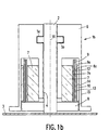
- Fig. 1b shows in cross-section a spindle motor 1b in a modified arrangement.
- the spindle motor of Fig. 2 corresponds to the spindle motor 1a of Fig. 1 in many respects. Corresponding parts have been given the same reference numerals.
- the motor shaft 2 of the spindle motor 1b of Fig. 2 is fixedly connected to the plate 3 of the hard disk housing (not shown).
- Two hydrodynamic axial bearings 5a and 5b support the hub 6 at the portion of the motor shaft 2 remote from the plate 3.
- a further hydrodynamic spiral bearing 4 is present close to a support plate 8.
- a permanent magnetic rotor magnet 7 is fastened on the hub 6.
- the support plate 8 is provided at the motor shaft 2 and supports the coil configuration 9 which consists of a bent foil winding and will be described further below.
- the outside 9a of the coil configuration 9 adjoins an air gap 13.
- the air gap 13 is bounded on the outside by a jacket-type yoke 10 of soft magnetic material.
- This yoke 10 is fixedly arranged at the inside 14 of the hub 6, which also has a jacket shape.
- the outer hub portion 6c provides space for the mounting of one or several hard disks.
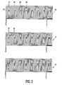
- Fig. 2 shows in plan view three foil windings 20, 21, 22. These three foils are to be rolled so as to form a three-phase winding for the hard disk motor.
- the rolled state is shown in perspective view in Fig. 4.
- Each single foil comprises, as Fig. 3 shows, a central synthetic resin foil 23 on whose two surfaces 23a and 23b copper foils 24 and 25 have been provided.
- the copper foils 24 and 25 were so etched in a generally known etching treatment that gaps 26 are created which separate individual copper conductor tracks 27 from one another, as is visible in Fig. 3.
- Planar coil windings 28 were thus formed on the foil 23 on both sides, which serve for motor excitation.
- the coils of the two foil sides are electrically interconnected from the upper to the lower side.
- the gaps 26 are filled up with an adhesive filler material.
- the adhesive filler material is a polymerizing glue.
- the glue has the property that it connects the planar conductor track portions 29a, 29b, 29c, 29d, 29e, 29f in a manner so stable that the planar conductor tracks 29 of the coil are interconnected again thereby with a dimensional stability as if the gaps 26 were still filled with the removed copper. Without etching, the copper would have allowed itself to be shaped into a perfectly round shape in the continuous state. Thanks to the filling of the gaps 26 with the adhesive filler glue, this is again achieved. Fig.
- FIG. 4 shows in perspective view how the three foil windings 20, 21, 22 are rolled up into a three-phase winding in a perfectly round shape.
- Fig. 5 shows a cross-section in which the perfect curvatures of the foils 20, 21 and 22 are shown even better.
- the perfect curvature renders it possible to keep the air gap of the motor small. Furthermore, a very good radial support is achieved by the construction of the hydrodynamic spiral groove bearings 4, 5a and 5b.
- the perfectly wound winding and the use of the spiral groove bearings minimize the radial bearing forces generated by the motor, and thus the deviation of the rotor axis. The result of this is that the motor has a longer life and/or allows for wider manufacturing tolerances. A higher packing density of the hard storage disks is furthermore facilitated thereby.
- the foil between the copper tracks has a thickness of approximately 20 ⁇ m, and the copper foils are provided to a thickness of approximately 110 ⁇ m.
Landscapes
- Engineering & Computer Science (AREA)
- Power Engineering (AREA)
- Manufacturing & Machinery (AREA)
- Windings For Motors And Generators (AREA)
- Manufacture Of Motors, Generators (AREA)
- Rotational Drive Of Disk (AREA)
Claims (6)
- Moteur électrique avec une partie de moteur stationnaire et une partie de moteur active mobile, l'une des deux parties de moteur actives comprenant un enroulement de moteur et l'autre un aimant de moteur, un entrefer étant formé entre lesdites parties de moteur actives tandis que l'enroulement de moteur (9) est constitué sur une feuille de support en résine synthétique et est formé par l'enlèvement local de la matière de cuivre par laquelle la feuille de résine synthétique (23) a été préalablement entièrement revêtue, caractérisé en ce que :la feuille de support en résine synthétique (23) et les bobines planes (28) qui y adhérent sont dotées d'une matière de charge adhésive (30) telle que la matière de charge adhésive (30) remplit les intervalles (26) formés entre les pistes conductrices individuelles par l'enlèvement de la matière de cuivre, etl'ensemble ainsi stabilisé est enroulé en un cylindre uniformément rond.
- Moteur électrique selon la revendication 1, caractérisé en ce que la matière de charge adhésive (30) remplissant les intervalles a une stabilité telle que les pistes conductrices planes (27) des bobines (28) sont en l'occurrence interconnectées avec une stabilité dimensionnelle comme si lesdits intervalles (26) étaient encore remplis du cuivre enlevé.
- Moteur électrique selon la revendication 2, caractérisé en ce que la matière de charge adhésive (30) recouvre aussi en une couche les surfaces supérieures des bobines planes (28) simultanément.
- Moteur électrique selon la revendication 2, caractérisé en ce que la colle polymérisante est utilisée comme matière de charge adhésive.
- Moteur électrique selon l'une ou plusieurs des revendications 2 à 4, caractérisé en ce que la matière de charge adhésive est appliquée par sérigraphie ou revêtement par rouleau.
- Entraínement de disque dur doté d'un moteur électrique conformément à l'une des revendications 1 à 5.
Applications Claiming Priority (3)
| Application Number | Priority Date | Filing Date | Title |
|---|---|---|---|
| DE4420371 | 1994-06-10 | ||
| DE4420371A DE4420371A1 (de) | 1994-06-10 | 1994-06-10 | Elektromotor, insbesondere für einen Festplattenantrieb, mit einem Stator und einem Rotor |
| PCT/IB1995/000428 WO1995034934A1 (fr) | 1994-06-10 | 1995-06-06 | Moteur electrique |
Publications (2)
| Publication Number | Publication Date |
|---|---|
| EP0764357A1 EP0764357A1 (fr) | 1997-03-26 |
| EP0764357B1 true EP0764357B1 (fr) | 1998-09-02 |
Family
ID=6520317
Family Applications (1)
| Application Number | Title | Priority Date | Filing Date |
|---|---|---|---|
| EP95918706A Expired - Lifetime EP0764357B1 (fr) | 1994-06-10 | 1995-06-06 | Moteur electrique |
Country Status (7)
| Country | Link |
|---|---|
| US (1) | US5955813A (fr) |
| EP (1) | EP0764357B1 (fr) |
| JP (1) | JPH10501678A (fr) |
| KR (1) | KR970704259A (fr) |
| DE (2) | DE4420371A1 (fr) |
| TW (1) | TW463448B (fr) |
| WO (1) | WO1995034934A1 (fr) |
Cited By (2)
| Publication number | Priority date | Publication date | Assignee | Title |
|---|---|---|---|---|
| US6278205B1 (en) | 1999-07-20 | 2001-08-21 | U.S. Philips Corpration | Electric motor with connector element on foil-shaped insulating substrate |
| US7123441B1 (en) | 1999-07-20 | 2006-10-17 | Koninklijke Philips Electronics N.V. | Electric motor having foil-shaped substrate with tracks with varying width |
Families Citing this family (15)
| Publication number | Priority date | Publication date | Assignee | Title |
|---|---|---|---|---|
| DK199900015A (da) | 1999-01-05 | 2000-07-06 | Kirk Acoustics As | Elektrisk miniaturemotor |
| WO2001045233A1 (fr) | 1999-12-17 | 2001-06-21 | Encap Motor Corporation | Moteur d'entrainement d'axe incorporant un stator et son procede de fabrication |
| US6909215B2 (en) * | 2000-01-28 | 2005-06-21 | John Graham Bryant | Electric motor |
| US7032349B2 (en) * | 2000-04-27 | 2006-04-25 | Atoma International Corp. | Coreless motor door closure system for motor vehicles |
| US7096566B2 (en) | 2001-01-09 | 2006-08-29 | Black & Decker Inc. | Method for making an encapsulated coil structure |
| US6946758B2 (en) | 2001-01-09 | 2005-09-20 | Black & Decker Inc. | Dynamoelectric machine having encapsulated coil structure with one or more of phase change additives, insert molded features and insulated pinion |
| CN100511924C (zh) | 2001-01-09 | 2009-07-08 | 布莱克-德克尔公司 | 一种转子涂复导热塑料的电动机 |
| US7814641B2 (en) | 2001-01-09 | 2010-10-19 | Black & Decker Inc. | Method of forming a power tool |
| US6483219B2 (en) * | 2001-03-20 | 2002-11-19 | Damco Limited | Electric motor |
| WO2005015712A1 (fr) * | 2003-08-09 | 2005-02-17 | Danfoss A/S | Procede de production d'une bobine pour un moteur electrique |
| US20050069234A1 (en) * | 2003-09-29 | 2005-03-31 | Takashi Kanai | Motor with aerodynamic bearing |
| GB201322478D0 (en) * | 2013-12-18 | 2014-02-05 | Gyo Gym Ltd | Improvements in or relating to generating your own power |
| US10491069B2 (en) * | 2014-09-16 | 2019-11-26 | Greentech Motors Corporation | Electric motor with laminated sheet windings |
| DE102017219972A1 (de) * | 2017-11-09 | 2019-05-09 | Bühler Motor GmbH | Eisenlose Folienwicklung und Elektromotor mit einer eisenlosen Folienwicklung |
| AU2019456625B2 (en) * | 2019-07-05 | 2023-01-05 | Renwei YU | Flat multi-layer coil stator for disk motor |
Family Cites Families (14)
| Publication number | Priority date | Publication date | Assignee | Title |
|---|---|---|---|---|
| US4384386A (en) * | 1978-09-22 | 1983-05-24 | The Scott & Fetzer Company | Motor for rotating brush |
| JPS5828838A (ja) * | 1981-08-14 | 1983-02-19 | Comput Basic Mach Technol Res Assoc | 薄膜磁気ヘッドの製造方法 |
| US4645961A (en) * | 1983-04-05 | 1987-02-24 | The Charles Stark Draper Laboratory, Inc. | Dynamoelectric machine having a large magnetic gap and flexible printed circuit phase winding |
| DE3526166C2 (de) * | 1984-07-23 | 1996-05-02 | Asahi Chemical Ind | Bürstenloser Elektromotor und Verfahren zum Herstellen einer Spuleneinheit für diesen |
| CA1266877A (fr) * | 1984-09-13 | 1990-03-20 | Erich Rabe | Machine a courant continu commutee electroniquement et son usage |
| JPS61180560A (ja) * | 1985-02-01 | 1986-08-13 | Kangiyou Denki Kiki Kk | 直流ブラシレスマイクロモ−タ |
| WO1989001258A1 (fr) * | 1987-08-03 | 1989-02-09 | Minebea Co., Ltd. | Bobine d'induit et procede de production d'une telle bobine |
| JPH01186143A (ja) * | 1988-01-19 | 1989-07-25 | Olympus Optical Co Ltd | 無鉄心電機子とその製造方法及び無鉄心電機子成形用金型 |
| EP0410293B1 (fr) * | 1989-07-24 | 1993-09-29 | Ebara Corporation | Moteur arbre |
| CH681840A5 (fr) * | 1991-08-20 | 1993-05-28 | Ver Drahtwerke Ag | |
| CH682780A5 (de) * | 1992-06-19 | 1993-11-15 | Ver Drahtwerke Ag | Elektrische Spule und Verfahren zu deren Herstellung. |
| DE4232666C1 (de) * | 1992-09-29 | 1994-03-24 | Presskon Ges Fuer Elektronisch | Verfahren zum Herstellen von Leiterplatten |
| JP2665134B2 (ja) * | 1993-09-03 | 1997-10-22 | 日本黒鉛工業株式会社 | フレキシブル回路基板及びその製造方法 |
| DE59508880D1 (de) * | 1994-03-04 | 2001-01-11 | Philips Corp Intellectual Pty | Elektromotor mit einem Stator und einem Rotor |
-
1994
- 1994-06-10 DE DE4420371A patent/DE4420371A1/de not_active Withdrawn
-
1995
- 1995-06-06 EP EP95918706A patent/EP0764357B1/fr not_active Expired - Lifetime
- 1995-06-06 JP JP8501878A patent/JPH10501678A/ja active Pending
- 1995-06-06 DE DE69504506T patent/DE69504506T2/de not_active Expired - Fee Related
- 1995-06-06 WO PCT/IB1995/000428 patent/WO1995034934A1/fr not_active Ceased
- 1995-06-07 US US08/488,324 patent/US5955813A/en not_active Expired - Fee Related
- 1995-07-04 TW TW084106847A patent/TW463448B/zh active
-
1996
- 1996-12-09 KR KR1019960707009A patent/KR970704259A/ko not_active Abandoned
Cited By (2)
| Publication number | Priority date | Publication date | Assignee | Title |
|---|---|---|---|---|
| US6278205B1 (en) | 1999-07-20 | 2001-08-21 | U.S. Philips Corpration | Electric motor with connector element on foil-shaped insulating substrate |
| US7123441B1 (en) | 1999-07-20 | 2006-10-17 | Koninklijke Philips Electronics N.V. | Electric motor having foil-shaped substrate with tracks with varying width |
Also Published As
| Publication number | Publication date |
|---|---|
| US5955813A (en) | 1999-09-21 |
| KR970704259A (ko) | 1997-08-09 |
| WO1995034934A1 (fr) | 1995-12-21 |
| EP0764357A1 (fr) | 1997-03-26 |
| DE4420371A1 (de) | 1995-12-14 |
| DE69504506T2 (de) | 1999-05-20 |
| TW463448B (en) | 2001-11-11 |
| DE69504506D1 (de) | 1998-10-08 |
| JPH10501678A (ja) | 1998-02-10 |
Similar Documents
| Publication | Publication Date | Title |
|---|---|---|
| US5714828A (en) | Electric motor having a stator and a rotor | |
| US5955813A (en) | Electric motor | |
| CA1336787C (fr) | Moteur integre dans l'arbre pour l'entrainement de lecteurs; methode de sa fabrication | |
| US4788465A (en) | Armature for DC motor | |
| JP2965240B2 (ja) | ディスク駆動装置 | |
| US4928029A (en) | In-spindle motor assembly for disk drive and method for fabricating | |
| KR19980701526A (ko) | 최소화된 방사상 정미 힘과 낮은 코깅 토크를 갖는 브러시리스 직류 모터(d.c. brushless motor with minimized net radial forcesand low cogging torque) | |
| JPH0442902B2 (fr) | ||
| EP0685843A1 (fr) | Unité de disque de bas profil, entraîné par moteur, pour appareil d'enregistrement/reproduction | |
| US6936940B2 (en) | Motor with resin base plate | |
| JPH0197152A (ja) | 磁石装置 | |
| US5093595A (en) | Spindle motor having reduced torque ripple | |
| US5726829A (en) | Axial spindle motor for hard disk drive assembly | |
| JP3358667B2 (ja) | ディスク回転用モータ | |
| US6603635B1 (en) | Motor structure for use with optical disks | |
| JP2532489Y2 (ja) | 刷子レスモータ | |
| GB2180413A (en) | Drive motor unit for signal-processing devices especially information-storage disk devices | |
| JP3503379B2 (ja) | ブラシレスモータ | |
| JP2591448Y2 (ja) | ブラシレスモータのステータ装置 | |
| JPS61185051A (ja) | 交流電動機 | |
| JPH03285547A (ja) | 偏平ブラシレスモータ | |
| CA2362686A1 (fr) | Moteur a courant continu a aimants permanents a entrefer de travail dispose radialement | |
| KR910004776Y1 (ko) | 직류모터의 회전자 | |
| EP0433037B1 (fr) | Moteur axe et unité de disque pourvue de celui-ci | |
| JPH08289522A (ja) | スピンドルモータ |
Legal Events
| Date | Code | Title | Description |
|---|---|---|---|
| PUAI | Public reference made under article 153(3) epc to a published international application that has entered the european phase |
Free format text: ORIGINAL CODE: 0009012 |
|
| 17P | Request for examination filed |
Effective date: 19970110 |
|
| AK | Designated contracting states |
Kind code of ref document: A1 Designated state(s): DE FR GB |
|
| GRAG | Despatch of communication of intention to grant |
Free format text: ORIGINAL CODE: EPIDOS AGRA |
|
| 17Q | First examination report despatched |
Effective date: 19970811 |
|
| GRAG | Despatch of communication of intention to grant |
Free format text: ORIGINAL CODE: EPIDOS AGRA |
|
| GRAH | Despatch of communication of intention to grant a patent |
Free format text: ORIGINAL CODE: EPIDOS IGRA |
|
| GRAH | Despatch of communication of intention to grant a patent |
Free format text: ORIGINAL CODE: EPIDOS IGRA |
|
| GRAA | (expected) grant |
Free format text: ORIGINAL CODE: 0009210 |
|
| AK | Designated contracting states |
Kind code of ref document: B1 Designated state(s): DE FR GB |
|
| REF | Corresponds to: |
Ref document number: 69504506 Country of ref document: DE Date of ref document: 19981008 |
|
| ET | Fr: translation filed | ||
| PLBE | No opposition filed within time limit |
Free format text: ORIGINAL CODE: 0009261 |
|
| STAA | Information on the status of an ep patent application or granted ep patent |
Free format text: STATUS: NO OPPOSITION FILED WITHIN TIME LIMIT |
|
| 26N | No opposition filed | ||
| PGFP | Annual fee paid to national office [announced via postgrant information from national office to epo] |
Ref country code: FR Payment date: 20010625 Year of fee payment: 7 |
|
| PGFP | Annual fee paid to national office [announced via postgrant information from national office to epo] |
Ref country code: GB Payment date: 20010629 Year of fee payment: 7 |
|
| PGFP | Annual fee paid to national office [announced via postgrant information from national office to epo] |
Ref country code: DE Payment date: 20010821 Year of fee payment: 7 |
|
| REG | Reference to a national code |
Ref country code: GB Ref legal event code: IF02 |
|
| PG25 | Lapsed in a contracting state [announced via postgrant information from national office to epo] |
Ref country code: GB Free format text: LAPSE BECAUSE OF NON-PAYMENT OF DUE FEES Effective date: 20020606 |
|
| PG25 | Lapsed in a contracting state [announced via postgrant information from national office to epo] |
Ref country code: DE Free format text: LAPSE BECAUSE OF NON-PAYMENT OF DUE FEES Effective date: 20030101 |
|
| GBPC | Gb: european patent ceased through non-payment of renewal fee |
Effective date: 20020606 |
|
| PG25 | Lapsed in a contracting state [announced via postgrant information from national office to epo] |
Ref country code: FR Free format text: LAPSE BECAUSE OF NON-PAYMENT OF DUE FEES Effective date: 20030228 |
|
| REG | Reference to a national code |
Ref country code: FR Ref legal event code: ST |