EP0764426A2 - Appareil de suture vasculaire - Google Patents
Appareil de suture vasculaire Download PDFInfo
- Publication number
- EP0764426A2 EP0764426A2 EP96115145A EP96115145A EP0764426A2 EP 0764426 A2 EP0764426 A2 EP 0764426A2 EP 96115145 A EP96115145 A EP 96115145A EP 96115145 A EP96115145 A EP 96115145A EP 0764426 A2 EP0764426 A2 EP 0764426A2
- Authority
- EP
- European Patent Office
- Prior art keywords
- needle
- jaw
- arm
- arms
- surgical
- Prior art date
- Legal status (The legal status is an assumption and is not a legal conclusion. Google has not performed a legal analysis and makes no representation as to the accuracy of the status listed.)
- Granted
Links
Images









Classifications
-
- A—HUMAN NECESSITIES
- A61—MEDICAL OR VETERINARY SCIENCE; HYGIENE
- A61B—DIAGNOSIS; SURGERY; IDENTIFICATION
- A61B17/00—Surgical instruments, devices or methods
- A61B17/28—Surgical forceps
- A61B17/29—Forceps for use in minimally invasive surgery
- A61B17/2909—Handles
-
- A—HUMAN NECESSITIES
- A61—MEDICAL OR VETERINARY SCIENCE; HYGIENE
- A61B—DIAGNOSIS; SURGERY; IDENTIFICATION
- A61B17/00—Surgical instruments, devices or methods
- A61B17/04—Surgical instruments, devices or methods for suturing wounds; Holders or packages for needles or suture materials
-
- A—HUMAN NECESSITIES
- A61—MEDICAL OR VETERINARY SCIENCE; HYGIENE
- A61B—DIAGNOSIS; SURGERY; IDENTIFICATION
- A61B17/00—Surgical instruments, devices or methods
- A61B17/04—Surgical instruments, devices or methods for suturing wounds; Holders or packages for needles or suture materials
- A61B17/06—Needles ; Sutures; Needle-suture combinations; Holders or packages for needles or suture materials
- A61B17/06061—Holders for needles or sutures, e.g. racks, stands
-
- A—HUMAN NECESSITIES
- A61—MEDICAL OR VETERINARY SCIENCE; HYGIENE
- A61B—DIAGNOSIS; SURGERY; IDENTIFICATION
- A61B17/00—Surgical instruments, devices or methods
- A61B17/28—Surgical forceps
- A61B17/2812—Surgical forceps with a single pivotal connection
- A61B17/2833—Locking means
-
- A—HUMAN NECESSITIES
- A61—MEDICAL OR VETERINARY SCIENCE; HYGIENE
- A61B—DIAGNOSIS; SURGERY; IDENTIFICATION
- A61B17/00—Surgical instruments, devices or methods
- A61B17/04—Surgical instruments, devices or methods for suturing wounds; Holders or packages for needles or suture materials
- A61B17/06—Needles ; Sutures; Needle-suture combinations; Holders or packages for needles or suture materials
- A61B17/06004—Means for attaching suture to needle
- A61B2017/06019—Means for attaching suture to needle by means of a suture-receiving lateral eyelet machined in the needle
-
- A—HUMAN NECESSITIES
- A61—MEDICAL OR VETERINARY SCIENCE; HYGIENE
- A61B—DIAGNOSIS; SURGERY; IDENTIFICATION
- A61B17/00—Surgical instruments, devices or methods
- A61B17/04—Surgical instruments, devices or methods for suturing wounds; Holders or packages for needles or suture materials
- A61B17/06—Needles ; Sutures; Needle-suture combinations; Holders or packages for needles or suture materials
- A61B17/06004—Means for attaching suture to needle
- A61B2017/06042—Means for attaching suture to needle located close to needle tip
-
- A—HUMAN NECESSITIES
- A61—MEDICAL OR VETERINARY SCIENCE; HYGIENE
- A61B—DIAGNOSIS; SURGERY; IDENTIFICATION
- A61B17/00—Surgical instruments, devices or methods
- A61B17/04—Surgical instruments, devices or methods for suturing wounds; Holders or packages for needles or suture materials
- A61B17/06—Needles ; Sutures; Needle-suture combinations; Holders or packages for needles or suture materials
- A61B17/06066—Needles, e.g. needle tip configurations
- A61B2017/0609—Needles, e.g. needle tip configurations having sharp tips at both ends, e.g. shuttle needle alternately retained and released by first and second facing jaws of a suturing instrument
-
- A—HUMAN NECESSITIES
- A61—MEDICAL OR VETERINARY SCIENCE; HYGIENE
- A61B—DIAGNOSIS; SURGERY; IDENTIFICATION
- A61B17/00—Surgical instruments, devices or methods
- A61B17/28—Surgical forceps
- A61B17/29—Forceps for use in minimally invasive surgery
- A61B2017/2926—Details of heads or jaws
- A61B2017/2932—Transmission of forces to jaw members
- A61B2017/2933—Transmission of forces to jaw members camming or guiding means
- A61B2017/2936—Pins in guiding slots
Definitions
- the technical field relates generally to surgical suturing instrumentation and, more particularly, to surgical suturing apparatus and method for suturing vascular tissue sections together.
- vascular tissues or vessels During many surgical procedures it is often necessary to join or even rejoin portions of vascular tissues or vessels to form an anastomosis.
- vascular tissues to create an anastomosis are used, such as, for example, suturing, stapling or clipping the ends of the vessels together.
- various stents may be used to join the vessels together and create the anastomosis. Where vessels are joined open end to open end it is termed an "end to end" anastomosis.
- suturing of vessels is preferred over stapling or clipping the vessels.
- a very small suturing needle is used having a length of suture material attached thereto to suture the vessels together.
- the suturing needle is typically grasped by a needle holder and passed through one vessel and then the opposite vessel. The procedure is repeated to thread or impart a series of stitches to the vessels to suture them together.
- the vascular sections to be sutured are typically extremely small. Suturing of such vascular tissue sections is often performed under magnification by equipping the surgeon with special magnifying glasses.
- the needle and suture material are passed through the vessels and pulled to draw the suture material through, it often becomes necessary to move the needle holder and needle from the field of view. This may require the surgeon to look away from the field of view containing the vessel sections to be sutured and may present problems in repositioning the needle within the magnified field of view to form another stitch in the vascular tissues and increases the time required to suture the vessels together.
- a surgical suturing apparatus and a method of suturing vessels which are particularly suited to suturing vascular tissues in anastomosis procedures. It would further be advantageous to have a surgical suturing apparatus which is operable with a single hand and is capable of maintaining precise and constant control of the needle as it is passed from one needle holding arm of the apparatus to another to avoid release of the needle during the suturing operation. It would also be advantageous to have a surgical suturing apparatus which is capable of suturing vascular tissue sections together with limited hand, apparatus and needle movement in order to maintain the entire suturing operation within a restricted field of view.
- the disclosed surgical apparatus for suturing vascular tissue sections includes a first arm having a first needle receiving recess and a first needle engaging member or blade mounted for movement with respect to the first arm.
- a second arm is provided and is mounted for movement with respect to the first arm and has a second needle receiving recess, the second arm having a second needle engaging member or blade mounted for movement with respect to the second arm.
- a reciprocating mechanism connected to the first and second needle engaging members and movable for alternately moving the first and second needle engaging members into and out of the first and second needle receiving recesses to secure a surgical needle therein.
- the reciprocating mechanism is movable between a first position advancing the first needle engaging member into engagement with the surgical needle and a second position advancing the second needle engaging member into engagement with the surgical needle.
- a camming member or lever is operatively associated with one of the arms for automatically camming the reciprocating mechanism between the first and second positions upon full closure of the first arm against the second arm.
- the reciprocating mechanism includes a toggle wheel rotatably affixed the arms and having first and second camming surfaces such that an initial closure of the arms forces the camming member into engagement with the first camming surface to move the toggle wheel to the first position. A subsequent closure of the arms forces the camming member into engagement with the second camming surface to move the toggle wheel to the second position.
- a surgical apparatus for suturing vascular tissue sections having first and second arms and first and second jaws positioned therein.
- a needle engaging member is mounted for movement in each jaw to enable clamping or release of the needle within the jaw.
- a camming member is provided to automatically move a reciprocating mechanism to slide the needle engaging member between the clamping and release position.
- a ratchet mechanism is provided to prevent opening of the arms until the stroke is completed to transfer the needle between the jaws and a jaw retaining mechanism locks the jaws together during transfer of the needle.
- a quick release mechanism may also be provided to enable the needle to be readily disengaged from the instrument and reloaded or replaced.
- a method of threading a suture through a vascular tissue section which includes the step of providing an apparatus having a first arm with a first needle receiving recess and a second arm with a second needle receiving recess, the first and second arms movable toward and away from each other.
- the method also includes the steps of holding a surgical needle within the second needle receiving recess, positioning the first and second arms about a first vascular tissue section to be sutured, moving the second arm toward the first arm such that the surgical needle pierces the first vascular tissue section and enters the first needle receiving recess and releasing the surgical needle from the second needle receiving recess and holding the surgical needle within the first needle receiving recess.
- the method also includes the step of moving the first arm away from the second arm to draw a suture affixed to the surgical needle at least partially through the first vascular tissue section.
- a vascular suturing apparatus 10 which is particularly suited to facilitate suturing vascular tissue sections or vessels together. Further, apparatus 10 is specifically designed to repeatedly pass a small surgical needle, having an associated length of suture material attached thereto, such as, for example, surgical needle 12 and suture 14, through vascular tissue sections while maintaining precise control of needle 12 during all phases of the suturing operation.
- Apparatus 10 generally includes a first or upper arm 16 movably connected to a second or lower arm 18. Arms 16 and 18 are movable toward and away from each other in order to repeatedly pass needle 12 therebetween in a manner described in detail hereinbelow.
- apparatus 10 is approximately 7 inches long.
- Apparatus 10 is preferably designed to handle surgical needles 12 having a length of approximately .1 to .5 inches and a diameter of approximately ten thousandths to .025 of an inch which are particularly suited for vascular surgery.
- the diameter of the surgical needle and the diameter of the suture are substantially the same to prevent fluid leakage from the vessel between the needle hole and suture.
- a surgical suturing instrument in an initially open position.
- a spring 20 which is affixed to proximal ends 22 and 24 of first and second (or upper and lower in the orientation of Fig. 1) arms 16 and 18, respectively.
- Spring 20 biases apart distal ends 26 and 28 of first and second arms 16 and 18, respectively, in order to facilitate positioning arms 16 and 18 about vascular tissue sections.
- the biasing action of spring 20 also aids in pulling suture 14 through the tissue sections upon opening of arms 16 and 18.
- Apparatus 10 further includes holding structure to secure needle 12 within either distal end 26 and 28 of arms 16 and 18, respectively.
- the holding structure allows surgical needle 12 to be initially held within one of the arms and, upon closure of the arms, to be subsequently passed to the opposite arm.
- a cam actuating lever 30 is provided to automatically actuate the holding structure upon closure of the arms.
- Cam actuating lever 30 is affixed to an extension arm 32 formed on arm 16. Extension arm 32 is sufficiently stiff to prevent depression of cam actuating lever 30 before arms 16 and 18 have been closed against the bias of spring 20.
- a pair of needle engaging members or clamping blades 34, 36 which are longitudinally movable within arms 16 and 18.
- a first needle engaging blade 34 is slidably disposed within first arm 16 while a second needle engaging member or second blade 36 is slidably disposed within second arm 18.
- Distal ends 38 and 40 of first and second blades 34 and 36, respectively, are dimensioned and configured to engage an edge of needle 12 and securely hold needle 12 within recesses 88, 90 formed in first and second arms 16 and 18.
- Arms 16 and 18 are formed with longitudinally extending channels 100 and 102 which extend from distal ends 38 and 40 to reciprocating mechanism 42. Channels 100 and 102 intersect recesses 88 and 90 to allow members 34 and 36 to engage an edge of surgical needle 12 disposed in the respective recess.
- needle engaging members 44, 46 are slightly bowed at regions 44a, 44b, respectively, thereby automatically adjusting to needles of various diameters. That is, as the needle is clamped, the needle engaging member buckles at a predetermined location so that the spring force applied to the needle is constant, regardless of the needle diameter. The needle engaging member is slightly buckled even when the needle is not clamped to ensure that the increased buckling occurs in the same area whenever the needle is clamped.
- blade engagement structure includes V-notches 106 and 108
- various other configurations at blade distal ends 38 and 40 may be provided to securely hold needle 12 within arms 16 and 18.
- alternate structure in either arms 16 or 18 or alternate structure in needle 12 itself such as, for example, notches in an edge of needle 12, or holes completely therethrough, may be provided to accept corresponding engagement structure formed on blades 34 and 36.
- a double-pointed surgical needle, or surgical incision member, having suture attachment structure intermediate the points may be utilized.
- a surgical incision member is disclosed in US Patent Application Serial No. 08/260,579, filed June 16, 1994, and entitled SURGICAL INCISION MEMBER the disclosure of which is incorporated by reference herein.
- a reciprocating mechanism 42 is affixed adjacent proximal ends 44 and 46 of first and second engaging members 34 and 36, respectively.
- Reciprocating mechanism 42 alternately advances and retracts engaging members 34 and 36, within arms 16 and 18, respectively, thereby alternately engaging the members 34 and 36 with needle 12.
- Reciprocating mechanism 42, along with first and second engaging members 34 and 36, provide the aforementioned holding structure for securely and alternately holding needle 12 within needle receiving recesses formed in arms 16 and 18.
- Cam actuating lever 30 actuates reciprocating mechanism 42 automatically upon full closure of arms 16 and 18.
- a lock member 48 which is flexibly mounted within a recess 50 in lower arm 18. Lock member 48 is engageable with reciprocating mechanism 42 to prevent movement of reciprocating mechanism 42, and thus release of needle 12, when arms 16 and 18 are in a open position, i.e., when cam actuating lever 30 has not been depressed.
- apparatus 10 is particularly suited to suturing small vessels or vascular tissue sections when viewed under magnification or within a restricted field of view. Further, suturing of vessels requires an extremely small needle 12 and suture 14, typically on the order of ten thousands of an inch in diameter.
- a pair of alignment pins 52 which are mounted on first arm 16. Upon closure of arm 16 towards arm 18, alignment pins 52 enter into guide holes 54 formed in lower arm 18. The engagement of alignment pins 52 within guide holes 54 is sufficiently precise to ensure accurate alignment of needle 12 within the recesses 88, 90 formed in distal ends 26 and 28 of arms 16 and 18, respectively.
- spacer block 56 which ensures that distal ends 26 and 28 of arms 16 and 18, respectively, do not touch upon closure. However, spacer block 56 does allow arms 16 and 18 to close sufficiently such that needle 12 may be transferred therebetween.
- Reciprocating mechanism 42 preferably includes a rotatable toggle wheel 60 which is provided to alternately advance or retract needle engaging members 34 and 36 in response to depression of cam actuating lever 30 upon full closure of arms 16 and 18, i.e. in response to movement of extension arm 32 with respect to arm 16.
- Toggle wheel 60 additionally provides recesses (described below) for engagement with lock member 48.
- first and second arms 16 and 18 are movably connected together and configured to be operated in a tweezer-like manner if desired.
- arms 16 and 18 are provided with a transverse pivot pin 62 for connecting and pivotally moving arms 16 and 18 with respect to each other.
- Pivot pin 62 is connected to arms 16 and 18 at a position intermediate proximal ends 22, 24 and distal end 26, 28 of arms 16 and 18, respectively.
- pivot pin 62 may be positioned at proximal ends 22 and 24.
- the preferred method of moving arms 16 and 18 is by pivotal motion, parallel movement of arms 16 and 18 is also contemplated. Parallel movement of arms 16 and 18 is especially desirable when using relatively straight surgical needles and may be accomplished in several ways. For example, arms 16 and 18 could be mounted with respect to each other to both move perpendicular to their respective longitudinal axes. Alternately, arms 16 and 18 could be mounted to move or slide parallel to their respective longitudinal axes to advance and retract their distal ends. When arms 16 and 18 slide relative to each other, it is preferable to have the distal faces of the arms open to a needle holding recess to facilitate transfer of a surgical needle or surgical incision member therebetween.
- Pin 62 further serves as a pivot point for toggle wheel 16 which is rotatable in the clockwise or counterclockwise direction about pin 62.
- proximal ends 44 and 46 of needle engaging members 34 and 36, respectively are affixed to toggle wheel 60 by means of pins 64 and 66, respectively (see Fig. 3).
- pins 64 and 66 respectively (see Fig. 3).
- toggle wheel 60 is provided with a first angled camming surface 68 having a first ledge 70 which, when engaged by cam actuating lever 30, translates to a clockwise rotation of toggle wheel 60 and thus a distal advancement of needle engaging member 34 and a proximal retraction of needle engaging member 36.
- a second angled camming surface 72 and second ledge 74 are provided, such that when engaged by cam actuating lever 30, toggle wheel 60 is rotated in a counterclockwise direction to advance member 36 and retract member 34.
- Toggle wheel 60 is provided with lock notches 76 and 78 which correspond to the distalmost advancement of first and second needle engaging members 34 and 36, respectively.
- lock member 48 engages lock notch 78
- engaging member 36 is locked into an advanced or distalmost position to securely hold needle 12 within arm 18.
- toggle wheel 60 is rotated clockwise to a position where lock member 48 engages lock notch 76
- needle engaging member 34 is locked into an advanced or distalmost position to secure needle 12 within arm 16.
- lock member 48 in conjunction with lock notches 76 and 78, prevents release and transfer of needle 12 when arms 16 and 18 are not fully closed.
- toggle wheel 60 is provided with a knock off pin 80 to aid lock member 48 in entering lock notches 76 and 78, the operation of which is described in more detail hereinbelow.
- cam actuating lever 30 is provided to automatically perform the dual sequential functions of unlocking toggle wheel 60 from engagement with lock member 48 and rotating toggle wheel 60.
- Cam actuating lever 30 generally includes a base portion 82 which is preferably affixed to arm extension member 32. Alternatively in a non-automatic version, base 82 may be separately movable with respect to extension member 32.
- Cam actuating lever 30 includes a flexible release leg 84 which is affixed to base 82 and which is provided to cam lock member 48 out of lock notches 76 or 78 and thus allow toggle wheel 60 to be rotated.
- Cam actuating lever 30 also includes a flexible toggle leg 86 formed parallel to release leg 84. Toggle leg 86 is engageable with angled camming surfaces 68 and 72 and ledges 70 and 74 in order to rotate toggle wheel 60.
- apparatus 10 is particularly suited to repeatedly pass surgical needle 12 back and forth between arms 16, 18 automatically upon full closure of the arms, i.e. closure of arms 16 and 18 with respect to one another and subsequent closure of arm extension 32 with respect to arm 16.
- distal ends 26 and 28 of arms 16 and 18, respectively are biased to an open position by spring 20.
- Needle 12 having an associated length of suture material 14 attached thereto, is positioned and held within distal end 28 of second (lower) arm 18 by needle engaging member 36.
- Alignment pins 52 are spaced from guide holes 54 and extension arm 32 is in an unbiased state holding camming lever 30 away from toggle wheel 60 in the initial position.
- needle 12 preferably has a radius of curvature which is substantially equal to the distance between either needle recess, described hereinbelow, and the pivot point, i.e., pin 62, of apparatus 10. In this manner the radius of curvature of surgical needle 12 matches the arc defined by the closure of arms 16 and 18.
- toggle wheel 60 is in a counterclockwise most position with lock member 48 in engagement with lock notch 78 of toggle wheel 60 to prevent rotation.
- surgical needle 12 is locked into second (lower) arm 18.
- a portion of angled camming surface 68 of toggle 60 is oriented at a position slightly proximal of a center line c of cam actuating lever 30, and, as best shown in Fig. 3, toggle leg 86 is spaced above toggle wheel 60 while release leg 84 is spaced above lock member 48.
- vascular suturing apparatus 10 to actuate vascular suturing apparatus 10, pressure is applied to first and second arms 16 and 18 at a point distal of pivot pin 62 in the direction of arrows X to cause jaws 16 and 18 to come to a closed position where distal ends 26 and 28 are in close cooperative alignment. Arms 16 and 18 are closed against the bias of spring 20 which now assumes a stressed state. As best shown in Fig. 6B, upon closure of arms 16 and 18, the center line C of cam actuating lever 30 and thus of release leg 84 is rotated into alignment above lock member 48. Note at this point, due to the relative stiffness of extension arm 32, arm 32 has not moved in relation to arm 16.
- toggle lever 86 to further rotate toggle wheel 60 in a clockwise direction. Clockwise rotation of toggle wheel 60 begins to advance upper needle engaging member 34 in a distal direction and retract lower needle engaging member 36 in a proximal direction.
- toggle leg 86 rotates toggle wheel 60 in a clockwise direction thereby causing knock off pin 80 to move release leg 84 away from and off of lock member 48.
- lock member 48 now rides along, and is held down by, a lower circumferential surface 104 of toggle wheel 60. Needle engaging members 34 and 36 continue to be advanced and retracted respectively.
- Fig. 9B and as noted above, when jaws 16 and 18 are in a closed position, surgical needle 12 is held within recesses 88 and 90 in distal ends 26 and 28, respectively.
- Plates 92 and 94 having reduced recess areas 96, 98 prevent surgical needle 12 from sliding out of recesses 88 and 90.
- surgical needle 12 is securely contained within jaws 16 and 18 although neither of the needle engaging members 34 are in engagement with surgical needle 12.
- This non-engagement of the needle engaging members 34, 36 is illustrated in Figs. 11A and 11B as the V-shaped camming edges 106, 108, respectively are out of contact with surgical needle 12.
- toggle wheel 60 rotating to a fully clockwise or final position.
- release lever 84 is held out of alignment with lock member 48 by means of knock off pin 80.
- lock notch 76 assumes a position directly above lock member 48 and lock member 48, being spring biased, moves upward within recess 50 to engage lock notch 76.
- toggle wheel 60 becomes locked out from further rotation. Any further depression of cam actuating lever 30 at this time will cause no further rotation of toggle wheel 60.
- toggle wheel 60 is in a clockwise position, upper needle engaging member 34 is in a distalmost position while lower needle engaging member 36 is in a proximalmost position.
- distal end 38 of needle engaging member 34 engages an edge of surgical needle 12 while distal end 40 of member 36 remains disassociated from surgical needle 12.
- V-shaped camming edge 106 of needle engaging member 34 cams or wedges surgical needle 12 within respective recess 88 and V-shaped camming edge 108 of needle engaging member 36 is moved to its proximalmost position spaced from surgical needle 12.
- surgical needle 12 has been transferred from arm 18 to arm 16 while containing needle 12 within recesses 88 and 90, thereby accomplishing the transfer of needle 12 from arms 18 to 16 without risk of release or escape of needle 12.
- surgical needle 12 is under the total and precise control of an operator during an entire suturing operation without risk of needle 12 being released. It can be appreciated from the discussion above that closure of arms 18 and 16 due to pressure thereon, automatically reciprocates needle securing members 34, 36 to transfer control of surgical needle 12 to the respective arm 16 and 18. Thus, by merely squeezing arms 16 and 18 together, surgical needle 12 is automatically transferred from arm 18 to arm 16 without additional effort or manipulations on the part of the user.
- Figs. 16A through 16I illustrate the use of vascular suturing apparatus 10 to attach a pair of vascular tissue sections.
- the operation of apparatus 10 is best described in terms of suturing open or free ends of vessels to form an end-to-end anastomosis procedure. It will be appreciated by those skilled in the art that a similar procedure and operation of apparatus 10 is readily applicable to suture an open end of a vascular tissue section to an incision in a side of a second vascular tissue second to form an end to side anastomosis or to suture the sides of vascular tissue sections to form a side to side anastomosis.
- vascular suturing apparatus 10 In order to facilitate discussion of the anastomosis procedure, the operation of vascular suturing apparatus 10 will be described solely in terms of arms 16 and 18, and their respective distal ends 26 and 28 along with surgical needle 12 and associated length of suture material 14. However, it will be appreciated that the working operations of vascular suturing apparatus 10 e.g. the passing of the surgical needle 12 between arms 16 and 18, are performed in the manner described above.
- Fig. 16A shows a pair of vascular tissue sections or vessels A and B.
- suturing of vascular tissue sections is typically accomplished under magnification or within a reduced field of view.
- ends A1 and B1 of vascular tissue sections A and B, respectively are prepared in known fashion to ensure that clean and undamaged tissues are sutured together.
- ends A1 and B1 are preferably everted or spread open in known fashion to create everted edges A2 and B2 in vessels A and B, respectively, (Fig. 16B).
- Vessels A and B are approximated to bring everted edges A2 and B2 into an abutting relationship as shown in Fig. 16C.
- vascular suturing apparatus 10 is brought within the field of view by manipulating distal ends 26 and 28 of arms 16 and 18, respectively, adjacent everted edges A2-B2.
- surgical needle 12 and associated length of suture material 14 initially contained within arm 18 are positioned adjacent one side of everted edges A2-B2 while distal end 26 of arm 16 is positioned adjacent an opposite edge of everted edges A2-B2.
- Arms 16 and 18 are closed together to insert needle 12 through everted edges A2-B2 and enter into distal end 26 on the opposite arm 16 (Fig. 16D). At this point continued operation of vascular suturing apparatus 10 causes control of surgical needle 12 to be automatically transferred from arm 18 to arm 16 in the manner described above. Additionally, as arms 16 and 18 are closed about everted edges A2-B2, spacer block 56 (described above with respect to Figs. 1 and 2A) maintains a working gap E between arms 16 and 18 to prevent undesired compression or possible crushing of everted edges A2-B2 of vascular tissue sections A and B.
- FIG. 16E Upon opening of arms 16 and 18, (Fig. 16E) surgical needle 12 is securely held within arm 16 and is drawn through the everted edges A2-B2 of vessels A and B along with a portion of length of suture material 14. In this manner, vessels A and B have been pierced and thereby have a suture stitch formed therein.
- length of suture material 14 may be tied off to form a single stitch in edges A2-B2.
- arms 16 and 18 may be closed in a manner described hereinabove to repass or transfer control of surgical needle 12 from arm 16 back to arm 18 and thus reposition the point of surgical needle 12 to again pierce tissue and form another stitch. Thereafter, jaws 16 and 18 may be opened with needle 12 securely held within jaw 18 and again positioned on opposite sides of everted edges A2-B2 to form another stitch (Fig. 16G). Thus, continued repetition of the above described procedure will form a series of overlapping stitches through everted edges A2-B2 as best illustrated in Figs. 16H and 16I.
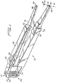
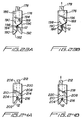
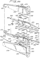
- FIGs. 25-40 An alternate embodiment of the vascular suturing apparatus is illustrated in Figs. 25-40. Similar to the apparatus 10 of Fig. 1, the apparatus of this second embodiment provides automatic transfer of the surgical needle between the two jaws, accomplished with a single hand of the user.
- apparatus 200 has an upper arm or housing 204 supporting an upper jaw 206 and a lower arm or housing 208 supporting a lower jaw 210.
- arms 204, 208 preferably have a knurled gripping surface and are configured to be grasped by the surgeon in a tweezer-like manner to facilitate control of the apparatus for suturing the tissue.
- Lower arm 208 and lower jaw 210 remain fixed as upper arm 204 and upper jaw 206 move relative thereto to pass the surgical needle 212, with attached suture 214, between jaws 206, 210.
- Surgical needle 212 like surgical needle 12 of the first embodiment, preferably has a length of approximately .1 to .5 inches and a diameter of approximately ten thousandths to .025 of an inch which are particularly suited for vascular surgery.
- the needle 212 can be straight as shown, although other needle sizes and configurations, such as curved needles, are also contemplated.
- the surgical needle and suture have substantially equal diameter.
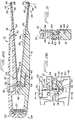
- upper arm 204 is dimensioned for partial insertion within a cavity 250 formed in lower arm 208 (see also Fig. 31). Cavity 222 of upper arm 204 is dimensioned and configured to receive upper jaw 206. Aperture 220 at the proximal end receives pivot pin 270 of lower jaw 210 to enable pivotal movement of jaw 206 with respect to jaw 10. Upper arm 204 is biased away from upper jaw 206, i.e. biased to the open position, by spring 232 which has a first end seated within slot 234 of upper arm 204 and a second end abutting surface 231 of upper jaw 206.
- Spring 232 can alternatively be in the form of a vertically oriented coil spring or other configuration for biasing the arm 204 away from upper jaw 206.
- Upper arm 204 includes a toggle finger 228 with a flexible release finger 230 for actuation of the wheels 302, 304 of the toggle mechanism to effect transfer of the needle between the jaws 206, 210.
- the toggle mechanism reciprocates the needle securing blades 330, 350 to alternately secure and release the surgical needle 212 from the respective jaw.
- Upper arm 204 also includes a ratchet finger 224 having a pawl 226 on its inner surface (not shown in Figure 26) which forms part of a ratchet mechanism for retaining the upper arm 204 and lower jaw 210 together during transfer of the surgical needle between the jaws 206, 210.
- jaws 206, 210 cannot be opened until the stroke is completed and the needle is safely secured in one of the jaws, thereby preventing premature opening of the jaws and loss of the needle before it is properly transferred to the opposing jaw.
- the ratchet and toggle mechanisms are discussed in detail below.
- Lower arm 208 of apparatus 200 has a cavity 250 formed between upstanding walls 253, 255 to receive lower jaw 210 as well as a portion of upper arm 204 (see also Fig. 31) when upper arm 204 is squeezed to the closed position.
- Lower jaw 210 and lower arm 208 remain fixed with respect to each other and with respect to upper arm 204 and upper jaw 206.
- Both lower and upper arms 204, 208 preferably taper in height towards their proximal end. It is also contemplated that alternately, both arms and jaws could pivot with respect to each other.
- Upper jaw 206 as shown in Fig. 26, has a distal end 264 designed to receive surgical needle 212 in recess 266 and co-operates with upper blade 330 to frictionally clamp the needle in a manner described below.
- Slot 268 is configured to receive the upper blade 330 which is also described below.
- a coil spring 325 which biases upper blade 330 proximally to a needle securing position, is seated within upper jaw 206 such that proximal hook 323 wraps around post 282 and distal hook 326 extends through slot 327 in upper blade 330, best shown in Figure 30.
- Lower jaw 210 has a pivot pin 270 at its proximal end 284 to engage aperture 220 of upper arm 204 to provide for pivotal movement of arm 204.
- Distal end 286 has a recess 288 for receiving the surgical needle 212 and a slot 290 for the lower blade 350 (Fig. 39).
- the lower blade 350 is biased proximally by coil spring 352 which, as shown in Fig. 30, has a proximal hook 354 wrapped around post 295 of lower jaw 210 and distal hook 356 extending through slot 358 in the lower blade 350.
- the distal end 286 is preferably configured with an inwardly sloped projecting portion 289. This is similar to the configuration of Fig. 21 which is described below.
- Support 292 formed in lower jaw 210 has a hole 293 for receiving the mounting pin of the wheels 302, 304 of the toggle mechanism.
- Aperture 294 and slot 296 are configured to mount release button 500, the function of which is described below.
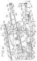
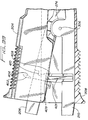
- a support leg 240 extends upwardly from one side of lower jaw 210 and forms part of the ratchet mechanism to prevent separation of the upper arm 204 and lower jaw 210 until the needle 212 is securely held in one of the jaws. More particularly, a rack 244 is positioned within cut-out portion 241 of lower jaw 210 and below projection 242 of support leg 240. As upper arm 204 is initially moved towards lower arm 208 to a closed position, ratchet finger 224, carrying pawl 226 on its inner surface, is initially biased distally by projection 242 such that pawl 226 extends into recess 243 of upper jaw 206.
- ratchet finger 224 snaps back in a proximal direction so that pawl 226 engages rack 244 as shown in Figure 36.
- the upper arm 204, and thus the upper jaw 210 cannot separate from the lower arm 206 and lower jaw 210 until the arms are fully closed and the pawl 226 completes its travel below the rack. (see Fig. 38)
- This completion of travel occurs only after the toggle mechanism has been fully actuated to release the needle 212 from one of the jaws and to secure the needle in the other jaw.
- separation of the jaws 206, 210 until the needle is safely transferred is prevented.
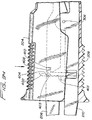
- the ratchet mechanism and its timing is discussed in more detail below in the description of the sequence of operation of the instrument.
- Retaining arm 401 extends upwardly and substantially parallel to ratchet finger 224 and as shown in Fig. 33, has a ledge or hook 408 and a projection 403 on its outer surface.
- ledge 408 of retaining arm 401 slightly engages a shelf 410 formed in an outer wall of the upper jaw 206 (see Fig. 34).
- retaining arm 401 springs back to its normal distal position. This disengages retaining arm 401 from shelf 410 to allow the upper jaw 206 to return to the open position.
- lower blade 350 is slidably mounted within lower jaw 210 for movement between a proximal position for clamping the surgical needle 212 and a distal position for releasing the needle 212. More specifically, distal end 364 has a recess defined by locking edge 358 which presses needle 212 against surface 269 of the lower jaw 210.
- coil spring 352 biases the lower blade 350 in a proximal direction such that biasing clip 370 (or alternately a biasing pin) engages angled surface 372 of the blade 350 to bias it into engagement with the needle 212 and to force it against surface 269 of lower jaw 210 to securely clamp the needle between the lower blade 350 and the lower jaw 210.
- the angled surface 372 is no longer in contact with biasing clip 370 and therefore the distal end 364 of blade 350 springs into slot 351 of lower jaw 210 and is also pushed into slot 351 by surface 269b.
- a sufficient gap 371 is provided to facilitate release of the needle.
- a bend 374 is formed in the lower blade 350 to cooperate with release button 500 in the manner described below.
- Upper blade 330 functions to retain the surgical needle 212 in the upper jaw 206 in an identical manner as lower blade 350. That is, the distal end 334 of upper blade 330 has a recess defined by a locking edge to clamp the surgical needle against a raised surface (not shown) of upper jaw 206. Upper blade 330 is biased proximally by coil spring 325 to a needle clamping position. A biasing clip or pin (not shown) biases the blade into engagement with the needle in the same manner as biasing clip 370 of lower needle securing blade 350. Step 336 provides the blade 330 with additional flexibility.
- the movement of the upper and lower blades 330, 350 are controlled by the toggle mechanism.
- the proximal end 362 of lower blade 350 tapers in width and in the illustrated embodiment angles downwardly to abut a portion of wheel 304 of the toggle mechanism.
- the proximal end 332 of upper blade 330 tapers in width and angles downwardly to abut another portion of wheel 304 of toggle mechanism. (It should be appreciated that alternately the downward angle could be eliminated and the proximal end of blades 330, 350 can be straight.) Consequently, as described in detail below, rotation (pivoting) of abutment wheel 304 slides the upper and lower blades 330, 350 between proximal and distal positions to alternately clamp and release the surgical needle 212 from the respective jaw.
- the toggle mechanism includes a toggle wheel 302 and a pivotable blade abutment wheel 304, both of which are rotatably mounted on mounting pin 306 within annular cavity 274 of upper jaw 206.
- Mounting pin 306 is fixedly secured in holes 275 and 293 of upper and lower jaws 206, 210, respectively.
- Toggle wheel 302 has a first angled camming surface and a first ledge designated by reference numerals 310, 311, respectively, and a second angled camming surface and second ledge designated by reference numerals 312, 313.
- Toggle wheel 302 further includes first and second locking notches 316, 314 and a knock-off pin 318 positioned therebetween.
- a locking spring 308 has a perpendicularly extending locking leg 324 engageable with one of the locking notches 314, 316 depending on the position of the toggle wheel 302. The opposite leg 326 of the locking spring 308 is seated within transverse slot 263 of upper jaw 206. This locking spring 308 prevents (blocks) movement of the toggle wheel 302 if the upper and lower arms 204, 208 are not in the closed position because locking spring 308 is disengaged (unlocked) from the respective locking notch only when upper arm 204 is moved to the closed position. By locking the toggle wheel 302, premature release of the needle 212, i.e. release of the needle before the opposing jaw has secured the needle, is prevented.
- Blade abutment wheel 304 has a first V-notch 320 which abuts the proximal end of upper blade 330 and a second V-notch 322 which abuts the proximal end of lower blade 350.
- blade abutment wheel 304 rotates clockwise as viewed in Fig 30, it slides upper blade 330 slightly distally, overcoming the force of coil spring 325, to release the surgical needle 212 from the upper jaw 206.
- Such clockwise movement simultaneously releases the distal force on coil spring 352 and allows coil spring 352 to bias lower jaw blade 350 proximally, thereby clamping the needle against the raised surface 269 of lower jaw 210 in the manner described above.
- counterclockwise movement of abutment wheel 304 allows coil spring 325 to bias upper blade 330 proximally into the needle clamping position and overcomes the force of coil spring 352 to force lower blade 350 distally into a needle release position.
- toggle finger 228 engages first ledge 311 causing toggle wheel 302 to rotate counterclockwise as shown in Fig. 38.
- This counterclockwise rotation of toggle wheel 302 causes abutment wheel 304 to rotate in the same direction, thereby sliding upper blade 330 proximally and lower blade 350 distally to clamp the needle 212 in the upper jaw 206 and release it from the lower jaw 210.
- knockoff pin 318 keeps release finger 230 out of the way so that locking leg 324 of locking spring 308 can engage the second locking notch 314 to retain toggle wheel 302 (and abutment wheel 304) in the second (counterclockwise) position.
- toggle leg 228 engages second camming surface 312 and second ledge 313 to rotate the toggle wheel 302 in a clockwise direction.
- Release finger 230 will force locking spring 308 out of engagement with the second locking notch 314 to enable it to reengage the first locking notch 316.
- Clockwise rotation of toggle wheel 302 will cause clockwise rotation of abutment wheel 304 to slide upper blade 330 to a distal release position and allow lower blade 350 to return to its proximal clamping position.
- the arms 204, 208 and jaws 206, 210 are in the open position with surgical needle 212 secured in the lower jaw 210 and spring 232 biasing the upper arm 204 away from the upper jaw 206.
- toggle wheel 302 and abutment wheel 304 are in the clockwise position such that lower blade 350 is biased proximally by coil spring 352 to clamp the surgical needle 212 in lower jaw 210 and upper blade 330 is forced into a distal (release) position by abutment wheel 304.
- locking leg 324 of locking spring 308 is engaged in the first locking notch 316 and release finger 230 is spaced therefrom.
- pawl 226 of the ratchet mechanism is spaced from projection 242 and rack 244 of leg 240, thus allowing free movement of the arms. Also, in this position, shown in Fig. 33, shelf 410 of upper jaw 206 is spaced from ledge 408 of retaining arm 401.
- arms 204, 208 are squeezed to move upper arm 204 and upper jaw 206 towards fixed lower arm 208 and lower jaw 210.
- upper arm 204 and jaw 206 move together towards lower jaw 210, with upper arm 204 remaining spaced from upper jaw 206 due to the biasing force of spring 232 and the engagement of pawl 226 of ratchet finger 224 in recess 243 of upper jaw 206.
- the upper and lower jaws 206, 210 are moved to a substantially closed position, parallel to one another as shown in Fig.
- release finger 230 has moved towards the locking spring 308 but remains out of engagement therewith and toggle finger 228 remains out of engagement with toggle wheel 302.
- Pawl 226 has almost completed its travel along projection 242 but remains out of engagement with rack 244 as it is biased into recess 243 of upper jaw 206 by projection 242.
- ledge 408 of retaining arm 401 has engaged shelf 410 of upper jaw 206 but is not securely held thereon because camming projection 402 remains out of engagement with projection 403 of retaining arm 401, as shown in Fig. 34.
- the ratchet mechanism will maintain upper arm 204 and lower jaw 210 together until the completion of the stroke and the transfer of the surgical needle 212 to the opposing jaw.
- camming surface 404 of the camming projection 402 of the jaw retaining mechanism engages the projection 403 of retaining arm 401 to begin to bias retaining arm 401 proximally to hold ledge 408 on shelf 410.
- camming projection 402 is retained in this position due to the engagement of pawl 226 and rack 244 on the other side of the apparatus which locks the upper arm 204 with respect to lower jaw 210.
- toggle leg 228 engages first angled camming surface 310 and begins to slide towards ledge 311.
- ledge 408 is retained on shelf 410 and pawl 226 is engaged in the lower teeth of rack 244, still maintaining the jaws 206, 210 in the closed position.
- toggle finger 228 engages first ledge 311 to rotate the toggle wheel 302 counterclockwise as shown in Fig. 38.
- abutment wheel 304 likewise rotates in the same direction to force lower blade 350 distally (see arrow D) against the force of coil spring 352 to release the surgical needle 212 from lower jaw 210.
- upper blade 330 is allowed to return (see arrow E) to its proximal (retracted) position under the force of coil spring 325.
- the upper blade 330 is moved to the locking position to clamp the needle 212 in the upper jaw 206 and the lower blade 350 moves into slot 351 to release the needle 212 from the lower jaw 210 (Fig. 38B).
- knock off pin 318 keeps release finger 230 away from locking leg 324 of locking spring 308, thus enabling the locking leg 324 to engage the second locking notch 314.
- Toggle wheel 302 (and abutment wheel 304) are thereby locked in this second (counterclockwise) position and thus upper blade 330 is locked in the proximal position to retain surgical needle 212. That is, since movement of the toggle wheel 302 is prevented, movement of the upper blade 330 to a release position is also prevented.
- Fig. 38 in this counterclockwise position of the toggle mechanism, i.e. when the toggle wheel 302 is locked in the second position so that the blades 330, 350 are locked, the pawl 226 is disengaged from rack 244 and can travel along the back side of the rack 244 to thereby allow the jaws 206, 210 to move to the open position.
- the position of arm retaining mechanism 400 at this time is illustrated in Fig. 38A.
- the camming projection 402 has moved from its position of Fig. 37A and slid past the projection 403 on retaining arm 401, thus allowing retaining arm 401 to spring back to its original distal position such that ledge 408 is out of engagement with shelf 410. This allows the upper jaw 206 to return to the open position.
- Fig. 39 illustrates the position of the toggle mechanism and the ratchet mechanism when the jaws 206, 210 and arms 204, 208 have returned to the open position with the surgical needle 212 secured in the upper jaw 206.
- the pawl 226 of the ratchet mechanism returns to the same position as in Fig. 30 (the jaw retaining mechanism also returns to the original position of Fig. 33).
- the toggle wheel 302 is maintained in the counterclockwise position by the engagement of locking leg 324 of locking spring 308 with second locking notch 314.
- the arms 204, 210 are closed, causing the jaw retaining mechanism and ratchet mechanism to engage as described above.
- the toggle finger 228 and release finger 230 will force the toggle wheel 302 and associated abutment wheel 304 to rotate clockwise to move the upper blade 330 distally to a release position and the lower blade 350 proximally to a clamping position to release the needle 212 from the upper jaw 206 and retain it in the lower jaw 210.
- the locking leg 324 of locking spring 308 will reengage the first locking notch 316 and when the arms 204, 208 and jaws 206, 210 are open, the apparatus' components will return to the position shown in Fig. 30.
- the apparatus 200 may include a quick release mechanism 500 to remove and replace or reload the surgical needle 212.
- the needle 212 needs to be positioned in the lower jaw 210 to use the quick release mechanism, however it is also contemplated that the release mechanism can be positioned on the upper jaw which would require the needle to be in the upper jaw in order to be replaced.
- arm 504 extends from pin 503 which is mounted in opening 294 of lower jaw 210.
- lever 502 is rotated clockwise, causing arm 504 to contact portion 373 of bend 374 of the lower blade 350. This forces the blade 350 distally to release the needle 212 from the jaw 210.
- needle 212 With the blade 350 in the distal position (see e.g. Fig. 38B), needle 212 can be removed through gap 371 between the lower blade 350 and lower jaw 210 and a fresh needle and suture can be inserted into gap 371 against raised surface 269 of lower jaw 10. Subsequently, lever 502 is released to return to its initial position of Fig. 30, allowing lower blade 350 to return to the proximal clamping position under the force of coil spring 352.
- apparatus 200 can be used to suture vascular tissue sections in the manner described above with respect to apparatus 10 and illustrated in Figs. 16A through 16I.
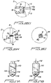
- Figs. 17A and 17B illustrate an alternate embodiment of a distal end arm configuration 110 and needle engaging member 112.
- Arm distal end 110 includes an enlarged bore 114 for receipt of a surgical needle 12.
- Bore 114 aids in positioning and transferring surgical needle 12 between arms especially when pushed through tough tissue sections which may cause deflection of surgical needle 12.
- Bore 114 includes a V-shaped notch 116 at a distalmost end which cooperates with a V-shaped camming edge 118 on needle engaging member 112.
- V-shaped camming edge 118 cams surgical needle 12 within bore 114 against notch 116 to securely hold surgical needle 12 therein.
- surgical needle 12 may be either smooth sided or notched adjacent an edge to receive at least a portion of V-shaped camming edge 118 of needle engaging member 112.
- Figs. 18A and 18B illustrate an alternate arm 120 and blade or needle engaging member 122 configuration which utilizes proximal retraction, rather than distal advancement, of engaging member 122 to securely hold surgical needle 12 against arm 120.
- Arm 120 includes a V-shaped engagement notch 124 formed on the distal end while needle engaging member 122 contains an elongated slot 126 for receipt of surgical needle 12 therein.
- Fig. 18B as blade 122 is retracted, surgical needle 12 disposed within slot 126 is cammed against and securely held within notch 124 in arm 120.
- Figs. 19A and 19B illustrate yet another alternate embodiment of an arm distal end 128 and needle engaging member 130 configuration best suited for securing a U-shaped, half-circle or otherwise relatively hollow surgical needle 132 which preferably has engagement structure in the form of an engagement hole 134 formed therethrough.
- Surgical needle 132 (Fig. 19C) may have various cross-sectional configurations while still having suitable engagement structure in the form of hole 134.
- Arm 128 has a bore 136 formed therein and needle engaging member 130 has a projecting tip 138 which preferably corresponds to the interior shape of the surgical needle 132.
- Needle engaging member 130 is further formed with a point or finger 140 formed on tip 138 and which is specifically designed to engage the engagement structure or hole 134 in surgical needle 132.
- distal advancement of needle engaging member 130 causes finger 140 to engage hole 134 and securely hold surgical needle 132 within arm 128.
- FIG. 20A and 20B an alternate arm 142 and needle engaging member 144 is shown for securely holding a round or otherwise preferably solid cross-sectional surgical needle 12 which enables easier loading.
- Arm 142 preferably includes an angled forward edge 146 and a groove or slot 148 proximal to angled forward edge 146.
- Needle engaging member 144 also includes an angled forward edge 150 and a camming member 152 formed at a distalmost portion of angled edge 150.
- camming member 152 upon retraction of needle engaging member 144 camming member 152 slides past edge 146 and forces surgical needle 12 into recess slot 148, thereby securing surgical needle 12 within arm 142.
- arm 166 is preferably formed with a V-shaped needle guiding recess 168 having a relatively round or circular needle receiving portion 170 at the apex of the V.
- Needle engaging member 172 includes an angled surface 174 which, when advanced as shown in Fig. 22B, cams against surgical needle 12 to firmly hold surgical needle 12 within circular recess 170 of arm 166.
- the easy load style of arm distal end configurations and needle engaging member configurations are particularly suited to parallel moving jaw structure which may either move perpendicular to the longitudinal axis of a surgical needle, that is, slide parallel to each other or may move parallel to the longitudinal axis of a surgical needle, i.e., that is, move perpendicular with respect to each other.
- Arm 176 preferably includes a single, distally extending hook 180 having an angled needle guiding front surface 182 and small semi-circular recess 184 disposed distally of angled needle guiding front surface 182. Additionally, a channel 186 for receipt of needle engaging member 178 includes a pair of angled camming surfaces 188 and 190. Needle engaging member 178 includes a distally extending camming finger 192 having a dog leg connecting portion 194 which connects finger 192 to the remainder of needle engaging member 178.
- Dog leg portion 194 has camming edges 196 and 198 which cooperate with camming edges 188, 190, respectively, in arm 176. As best shown in Fig. 23B, as needle engaging member 178 is retracted, camming edge 196 abuts camming edge 188 to move finger 192 sideways forcing surgical needle 12 to be firmly held within recess 184 in arm 176. Similarly, distal advancement of needle engaging member 178 results in abutting camming edge 190 of arm 178 to engage cam edge 198 to again move finger 192 sideways away from recess 184 thereby releasing surgical needle 12 from arm 176.
- Figs. 24A and 24B illustrate a further alternate embodiment of an easy load style arm and needle engaging member configuration.
- Arm 200 preferably includes a V-shaped needle guiding distal end 202 terminating in an elongated slot or recess 204 for receipt of surgical needle 12 therein.
- arm 200 has an elongated needle engaging member channel 206 having angled edges 208 and 210.
- Needle engaging member 212 includes a dog leg end portion 214 similar to that described with respect to the embodiment disclosed in Figs. 23A and 23B and contains a hook or recess edge 216 at the distalmost end thereof.
- Fig. 23A and 23B contains a hook or recess edge 216 at the distalmost end thereof.
- a camming edge 218 on needle engaging member 212 engages angled edge 208 on arm 200 to move needle engaging member 212 sideways thereby capturing surgical needle 12 within recess 204 by curved finger or hook 216.
- distal advancement of needle engaging member 212 within channel 206 causes a camming edge 220 on needle engaging member 212 to engage angled edge 210 on arm 200 to move hook 216 away from recess 204 thereby releasing surgical needle 12 from arm 200.
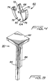
- arm 154 is illustrated which is particularly suited for use with a single pointed surgical needle 12 having an associated length of suture material 14 extending from an opposite end of the point.
- Arm 154 is configured to manage and manipulate suture material 14 such that it does not interfere with the transfer of surgical needle 12 from an opposing arm similar to arm 16.
- arm 154 includes angular inwardly sloped projecting portion 156 having a recess 158 therethrough.
- Recess 158 has a slot 160 along one edge thereof to allow suture material 14 to pass therethrough.
- projecting portion 156 is further formed with a chamfered or channelling surface 162 which serves to guide suture material 14 through slot 160 and into recess 158.
- a distal end of a needle engaging member may abut surgical needle 12 to hold it within recess 158 or, alternatively, a side edge of needle engaging member may cam against an edge of surgical needle 12 to hold it within recess 158.
Landscapes
- Health & Medical Sciences (AREA)
- Surgery (AREA)
- Life Sciences & Earth Sciences (AREA)
- Biomedical Technology (AREA)
- Nuclear Medicine, Radiotherapy & Molecular Imaging (AREA)
- Engineering & Computer Science (AREA)
- Heart & Thoracic Surgery (AREA)
- Medical Informatics (AREA)
- Molecular Biology (AREA)
- Animal Behavior & Ethology (AREA)
- General Health & Medical Sciences (AREA)
- Public Health (AREA)
- Veterinary Medicine (AREA)
- Ophthalmology & Optometry (AREA)
- Surgical Instruments (AREA)
Applications Claiming Priority (2)
| Application Number | Priority Date | Filing Date | Title |
|---|---|---|---|
| US532908 | 1990-06-04 | ||
| US53290895A | 1995-09-22 | 1995-09-22 |
Publications (3)
| Publication Number | Publication Date |
|---|---|
| EP0764426A2 true EP0764426A2 (fr) | 1997-03-26 |
| EP0764426A3 EP0764426A3 (fr) | 1997-07-30 |
| EP0764426B1 EP0764426B1 (fr) | 2005-11-23 |
Family
ID=24123696
Family Applications (1)
| Application Number | Title | Priority Date | Filing Date |
|---|---|---|---|
| EP19960115145 Expired - Lifetime EP0764426B1 (fr) | 1995-09-22 | 1996-09-20 | Appareil de suture vasculaire |
Country Status (4)
| Country | Link |
|---|---|
| EP (1) | EP0764426B1 (fr) |
| CA (1) | CA2186077C (fr) |
| DE (1) | DE69635467T2 (fr) |
| ES (1) | ES2250982T3 (fr) |
Cited By (8)
| Publication number | Priority date | Publication date | Assignee | Title |
|---|---|---|---|---|
| WO2010002904A1 (fr) * | 2008-07-03 | 2010-01-07 | Edwards Lifesciences Corporation | Instruments chirurgicaux à manche pour des opérations chirurgicales à accès à distance |
| GB2487971A (en) * | 2011-02-11 | 2012-08-15 | Leeds Teaching Hospitals Nhs Trust | Skin suturing device which can secure a drain |
| WO2013032329A1 (fr) | 2011-08-30 | 2013-03-07 | Med-Ip B.V. | Appareil de suture chirurgicale |
| CN108760489A (zh) * | 2018-05-08 | 2018-11-06 | 北京工业大学 | 皮肤软组织生物力学参数测量的装置及方法 |
| JP2019509118A (ja) * | 2016-03-11 | 2019-04-04 | メロン メディカル ビー ブイ | 手術用縫合装置 |
| CN113069159A (zh) * | 2021-03-26 | 2021-07-06 | 象山县第一人民医院医疗健康集团 | 一种肺部手术用缝合器 |
| US11806007B2 (en) | 2018-05-25 | 2023-11-07 | Suturion Ab | Suturing device |
| CN120284356A (zh) * | 2025-05-26 | 2025-07-11 | 卢德华 | 一种血管缝合机及血管缝合设备 |
Family Cites Families (7)
| Publication number | Priority date | Publication date | Assignee | Title |
|---|---|---|---|---|
| FR337579A (fr) * | 1903-12-11 | 1904-04-15 | Philippe Lepine | Nouvelle pince automatique pour sutures profondes |
| GB586661A (en) * | 1944-11-13 | 1947-03-26 | Singer Mfg Co | Surgical stitching instrument |
| DE1251905B (de) * | 1963-07-24 | 1967-10-12 | C V Heljestrand Ab | Geraet zur Anbringung von chirurgischen Naehten |
| GB2287196B (en) * | 1991-09-30 | 1995-11-15 | Philip Richardson | A surgical incision member for use in suturing |
| US5289963A (en) * | 1991-10-18 | 1994-03-01 | United States Surgical Corporation | Apparatus and method for applying surgical staples to attach an object to body tissue |
| US5344061A (en) * | 1993-08-03 | 1994-09-06 | Lawrence Crainich | Ratchet assembly for medical instrument |
| CA2133377C (fr) * | 1993-10-08 | 2004-09-14 | H. Jonathan Tovey | Appareil de suture chirurgicale dote d'un mecanisme de chargement |
-
1996
- 1996-09-20 CA CA002186077A patent/CA2186077C/fr not_active Expired - Fee Related
- 1996-09-20 DE DE1996635467 patent/DE69635467T2/de not_active Expired - Lifetime
- 1996-09-20 ES ES96115145T patent/ES2250982T3/es not_active Expired - Lifetime
- 1996-09-20 EP EP19960115145 patent/EP0764426B1/fr not_active Expired - Lifetime
Cited By (15)
| Publication number | Priority date | Publication date | Assignee | Title |
|---|---|---|---|---|
| WO2010002904A1 (fr) * | 2008-07-03 | 2010-01-07 | Edwards Lifesciences Corporation | Instruments chirurgicaux à manche pour des opérations chirurgicales à accès à distance |
| GB2487971B (en) * | 2011-02-11 | 2016-11-09 | The Leeds Teaching Hospitals Nhs Trust | Skin suture insertion apparatus and drain securing apparatus |
| GB2487971A (en) * | 2011-02-11 | 2012-08-15 | Leeds Teaching Hospitals Nhs Trust | Skin suturing device which can secure a drain |
| AU2012302365B2 (en) * | 2011-08-30 | 2016-12-15 | Mellon Medical B.V. | A surgical suture apparatus |
| JP2014529461A (ja) * | 2011-08-30 | 2014-11-13 | メロン メディカル ビー ブイ | 外科用縫合装置 |
| CN103917171A (zh) * | 2011-08-30 | 2014-07-09 | 梅隆医疗有限责任公司 | 外科手术缝合器械 |
| WO2013032329A1 (fr) | 2011-08-30 | 2013-03-07 | Med-Ip B.V. | Appareil de suture chirurgicale |
| US10085741B2 (en) | 2011-08-30 | 2018-10-02 | Mellon Medical B.V. | Surgical suture apparatus |
| JP2019509118A (ja) * | 2016-03-11 | 2019-04-04 | メロン メディカル ビー ブイ | 手術用縫合装置 |
| CN108760489A (zh) * | 2018-05-08 | 2018-11-06 | 北京工业大学 | 皮肤软组织生物力学参数测量的装置及方法 |
| US11806007B2 (en) | 2018-05-25 | 2023-11-07 | Suturion Ab | Suturing device |
| CN118806354A (zh) * | 2018-05-25 | 2024-10-22 | 苏图里恩公司 | 缝合装置 |
| US12396723B2 (en) | 2018-05-25 | 2025-08-26 | Suturion Ab | Suturing device |
| CN113069159A (zh) * | 2021-03-26 | 2021-07-06 | 象山县第一人民医院医疗健康集团 | 一种肺部手术用缝合器 |
| CN120284356A (zh) * | 2025-05-26 | 2025-07-11 | 卢德华 | 一种血管缝合机及血管缝合设备 |
Also Published As
| Publication number | Publication date |
|---|---|
| EP0764426B1 (fr) | 2005-11-23 |
| DE69635467T2 (de) | 2006-08-03 |
| DE69635467D1 (de) | 2005-12-29 |
| EP0764426A3 (fr) | 1997-07-30 |
| ES2250982T3 (es) | 2006-04-16 |
| CA2186077A1 (fr) | 1998-03-21 |
| CA2186077C (fr) | 2006-08-01 |
Similar Documents
| Publication | Publication Date | Title |
|---|---|---|
| EP0705568B1 (fr) | Appareil de suture vasculaire | |
| EP0705569B1 (fr) | Appareil endoscopique de suture vasculaire | |
| EP0836832B1 (fr) | Instrument de suture | |
| JP3662609B2 (ja) | 装填機構を備えた手術用縫合装置 | |
| US5645552A (en) | Surgical apparatus for suturing body tissue | |
| US5871488A (en) | Surgical suturing apparatus with locking mechanisms | |
| EP1337190B1 (fr) | Procede et instrument de suture | |
| US5478344A (en) | Surgical suturing apparatus with loading mechanism | |
| CA2186077C (fr) | Appareil pour suture vasculaire | |
| CA2537608C (fr) | Appareil pour suture vasculaire | |
| EP4279017A1 (fr) | Système de préparation de greffe de tissu | |
| CA2507239C (fr) | Appareil endoscopique pour suture de tissu vasculaire | |
| CA2468821C (fr) | Appareil de suture chirurgicale dote d'un mecanisme de chargement |
Legal Events
| Date | Code | Title | Description |
|---|---|---|---|
| PUAI | Public reference made under article 153(3) epc to a published international application that has entered the european phase |
Free format text: ORIGINAL CODE: 0009012 |
|
| AK | Designated contracting states |
Kind code of ref document: A2 Designated state(s): DE ES FR GB IT |
|
| PUAL | Search report despatched |
Free format text: ORIGINAL CODE: 0009013 |
|
| AK | Designated contracting states |
Kind code of ref document: A3 Designated state(s): DE ES FR GB IT |
|
| 17P | Request for examination filed |
Effective date: 19971126 |
|
| 17Q | First examination report despatched |
Effective date: 20011213 |
|
| GRAP | Despatch of communication of intention to grant a patent |
Free format text: ORIGINAL CODE: EPIDOSNIGR1 |
|
| GRAS | Grant fee paid |
Free format text: ORIGINAL CODE: EPIDOSNIGR3 |
|
| GRAA | (expected) grant |
Free format text: ORIGINAL CODE: 0009210 |
|
| AK | Designated contracting states |
Kind code of ref document: B1 Designated state(s): DE ES FR GB IT |
|
| REG | Reference to a national code |
Ref country code: GB Ref legal event code: FG4D |
|
| REF | Corresponds to: |
Ref document number: 69635467 Country of ref document: DE Date of ref document: 20051229 Kind code of ref document: P |
|
| REG | Reference to a national code |
Ref country code: ES Ref legal event code: FG2A Ref document number: 2250982 Country of ref document: ES Kind code of ref document: T3 |
|
| ET | Fr: translation filed | ||
| PLBE | No opposition filed within time limit |
Free format text: ORIGINAL CODE: 0009261 |
|
| STAA | Information on the status of an ep patent application or granted ep patent |
Free format text: STATUS: NO OPPOSITION FILED WITHIN TIME LIMIT |
|
| 26N | No opposition filed |
Effective date: 20060824 |
|
| PGFP | Annual fee paid to national office [announced via postgrant information from national office to epo] |
Ref country code: IT Payment date: 20100929 Year of fee payment: 15 |
|
| PGFP | Annual fee paid to national office [announced via postgrant information from national office to epo] |
Ref country code: ES Payment date: 20110926 Year of fee payment: 16 |
|
| PG25 | Lapsed in a contracting state [announced via postgrant information from national office to epo] |
Ref country code: IT Free format text: LAPSE BECAUSE OF NON-PAYMENT OF DUE FEES Effective date: 20120920 |
|
| REG | Reference to a national code |
Ref country code: ES Ref legal event code: FD2A Effective date: 20131021 |
|
| PG25 | Lapsed in a contracting state [announced via postgrant information from national office to epo] |
Ref country code: ES Free format text: LAPSE BECAUSE OF NON-PAYMENT OF DUE FEES Effective date: 20120921 |
|
| PGFP | Annual fee paid to national office [announced via postgrant information from national office to epo] |
Ref country code: GB Payment date: 20140929 Year of fee payment: 19 Ref country code: FR Payment date: 20140917 Year of fee payment: 19 |
|
| PGFP | Annual fee paid to national office [announced via postgrant information from national office to epo] |
Ref country code: DE Payment date: 20140929 Year of fee payment: 19 |
|
| REG | Reference to a national code |
Ref country code: DE Ref legal event code: R119 Ref document number: 69635467 Country of ref document: DE |
|
| GBPC | Gb: european patent ceased through non-payment of renewal fee |
Effective date: 20150920 |
|
| REG | Reference to a national code |
Ref country code: FR Ref legal event code: ST Effective date: 20160531 |
|
| PG25 | Lapsed in a contracting state [announced via postgrant information from national office to epo] |
Ref country code: GB Free format text: LAPSE BECAUSE OF NON-PAYMENT OF DUE FEES Effective date: 20150920 Ref country code: DE Free format text: LAPSE BECAUSE OF NON-PAYMENT OF DUE FEES Effective date: 20160401 |
|
| PG25 | Lapsed in a contracting state [announced via postgrant information from national office to epo] |
Ref country code: FR Free format text: LAPSE BECAUSE OF NON-PAYMENT OF DUE FEES Effective date: 20150930 |