EP0764498A2 - Bohrständer mit schwenkbarem Tisch - Google Patents
Bohrständer mit schwenkbarem Tisch Download PDFInfo
- Publication number
- EP0764498A2 EP0764498A2 EP96306829A EP96306829A EP0764498A2 EP 0764498 A2 EP0764498 A2 EP 0764498A2 EP 96306829 A EP96306829 A EP 96306829A EP 96306829 A EP96306829 A EP 96306829A EP 0764498 A2 EP0764498 A2 EP 0764498A2
- Authority
- EP
- European Patent Office
- Prior art keywords
- post
- supported
- opening
- chuck
- machine tool
- Prior art date
- Legal status (The legal status is an assumption and is not a legal conclusion. Google has not performed a legal analysis and makes no representation as to the accuracy of the status listed.)
- Withdrawn
Links
- 230000000284 resting effect Effects 0.000 claims 1
- 238000005266 casting Methods 0.000 description 17
- 230000003247 decreasing effect Effects 0.000 description 1
- 238000005553 drilling Methods 0.000 description 1
- 230000007774 longterm Effects 0.000 description 1
- 238000012423 maintenance Methods 0.000 description 1
Images






Classifications
-
- B—PERFORMING OPERATIONS; TRANSPORTING
- B23—MACHINE TOOLS; METAL-WORKING NOT OTHERWISE PROVIDED FOR
- B23Q—DETAILS, COMPONENTS, OR ACCESSORIES FOR MACHINE TOOLS, e.g. ARRANGEMENTS FOR COPYING OR CONTROLLING; MACHINE TOOLS IN GENERAL CHARACTERISED BY THE CONSTRUCTION OF PARTICULAR DETAILS OR COMPONENTS; COMBINATIONS OR ASSOCIATIONS OF METAL-WORKING MACHINES, NOT DIRECTED TO A PARTICULAR RESULT
- B23Q3/00—Devices holding, supporting, or positioning work or tools, of a kind normally removable from the machine
- B23Q3/02—Devices holding, supporting, or positioning work or tools, of a kind normally removable from the machine for mounting on a work-table, tool-slide, or analogous part
- B23Q3/06—Work-clamping means
- B23Q3/069—Work-clamping means for pressing workpieces against a work-table
-
- B—PERFORMING OPERATIONS; TRANSPORTING
- B23—MACHINE TOOLS; METAL-WORKING NOT OTHERWISE PROVIDED FOR
- B23Q—DETAILS, COMPONENTS, OR ACCESSORIES FOR MACHINE TOOLS, e.g. ARRANGEMENTS FOR COPYING OR CONTROLLING; MACHINE TOOLS IN GENERAL CHARACTERISED BY THE CONSTRUCTION OF PARTICULAR DETAILS OR COMPONENTS; COMBINATIONS OR ASSOCIATIONS OF METAL-WORKING MACHINES, NOT DIRECTED TO A PARTICULAR RESULT
- B23Q1/00—Members which are comprised in the general build-up of a form of machine, particularly relatively large fixed members
- B23Q1/03—Stationary work or tool supports
-
- B—PERFORMING OPERATIONS; TRANSPORTING
- B23—MACHINE TOOLS; METAL-WORKING NOT OTHERWISE PROVIDED FOR
- B23Q—DETAILS, COMPONENTS, OR ACCESSORIES FOR MACHINE TOOLS, e.g. ARRANGEMENTS FOR COPYING OR CONTROLLING; MACHINE TOOLS IN GENERAL CHARACTERISED BY THE CONSTRUCTION OF PARTICULAR DETAILS OR COMPONENTS; COMBINATIONS OR ASSOCIATIONS OF METAL-WORKING MACHINES, NOT DIRECTED TO A PARTICULAR RESULT
- B23Q1/00—Members which are comprised in the general build-up of a form of machine, particularly relatively large fixed members
- B23Q1/25—Movable or adjustable work or tool supports
- B23Q1/44—Movable or adjustable work or tool supports using particular mechanisms
- B23Q1/50—Movable or adjustable work or tool supports using particular mechanisms with rotating pairs only, the rotating pairs being the first two elements of the mechanism
- B23Q1/54—Movable or adjustable work or tool supports using particular mechanisms with rotating pairs only, the rotating pairs being the first two elements of the mechanism two rotating pairs only
- B23Q1/5406—Movable or adjustable work or tool supports using particular mechanisms with rotating pairs only, the rotating pairs being the first two elements of the mechanism two rotating pairs only a single rotating pair followed perpendicularly by a single rotating pair
-
- B—PERFORMING OPERATIONS; TRANSPORTING
- B23—MACHINE TOOLS; METAL-WORKING NOT OTHERWISE PROVIDED FOR
- B23Q—DETAILS, COMPONENTS, OR ACCESSORIES FOR MACHINE TOOLS, e.g. ARRANGEMENTS FOR COPYING OR CONTROLLING; MACHINE TOOLS IN GENERAL CHARACTERISED BY THE CONSTRUCTION OF PARTICULAR DETAILS OR COMPONENTS; COMBINATIONS OR ASSOCIATIONS OF METAL-WORKING MACHINES, NOT DIRECTED TO A PARTICULAR RESULT
- B23Q1/00—Members which are comprised in the general build-up of a form of machine, particularly relatively large fixed members
- B23Q1/25—Movable or adjustable work or tool supports
- B23Q1/44—Movable or adjustable work or tool supports using particular mechanisms
- B23Q1/50—Movable or adjustable work or tool supports using particular mechanisms with rotating pairs only, the rotating pairs being the first two elements of the mechanism
- B23Q1/54—Movable or adjustable work or tool supports using particular mechanisms with rotating pairs only, the rotating pairs being the first two elements of the mechanism two rotating pairs only
- B23Q1/5406—Movable or adjustable work or tool supports using particular mechanisms with rotating pairs only, the rotating pairs being the first two elements of the mechanism two rotating pairs only a single rotating pair followed perpendicularly by a single rotating pair
- B23Q1/5412—Movable or adjustable work or tool supports using particular mechanisms with rotating pairs only, the rotating pairs being the first two elements of the mechanism two rotating pairs only a single rotating pair followed perpendicularly by a single rotating pair followed perpendicularly by a single rotating pair
-
- B—PERFORMING OPERATIONS; TRANSPORTING
- B23—MACHINE TOOLS; METAL-WORKING NOT OTHERWISE PROVIDED FOR
- B23Q—DETAILS, COMPONENTS, OR ACCESSORIES FOR MACHINE TOOLS, e.g. ARRANGEMENTS FOR COPYING OR CONTROLLING; MACHINE TOOLS IN GENERAL CHARACTERISED BY THE CONSTRUCTION OF PARTICULAR DETAILS OR COMPONENTS; COMBINATIONS OR ASSOCIATIONS OF METAL-WORKING MACHINES, NOT DIRECTED TO A PARTICULAR RESULT
- B23Q1/00—Members which are comprised in the general build-up of a form of machine, particularly relatively large fixed members
- B23Q1/72—Auxiliary arrangements; Interconnections between auxiliary tables and movable machine elements
- B23Q1/74—Auxiliary tables
-
- B—PERFORMING OPERATIONS; TRANSPORTING
- B23—MACHINE TOOLS; METAL-WORKING NOT OTHERWISE PROVIDED FOR
- B23Q—DETAILS, COMPONENTS, OR ACCESSORIES FOR MACHINE TOOLS, e.g. ARRANGEMENTS FOR COPYING OR CONTROLLING; MACHINE TOOLS IN GENERAL CHARACTERISED BY THE CONSTRUCTION OF PARTICULAR DETAILS OR COMPONENTS; COMBINATIONS OR ASSOCIATIONS OF METAL-WORKING MACHINES, NOT DIRECTED TO A PARTICULAR RESULT
- B23Q3/00—Devices holding, supporting, or positioning work or tools, of a kind normally removable from the machine
- B23Q3/005—Guides for workpieces
-
- Y—GENERAL TAGGING OF NEW TECHNOLOGICAL DEVELOPMENTS; GENERAL TAGGING OF CROSS-SECTIONAL TECHNOLOGIES SPANNING OVER SEVERAL SECTIONS OF THE IPC; TECHNICAL SUBJECTS COVERED BY FORMER USPC CROSS-REFERENCE ART COLLECTIONS [XRACs] AND DIGESTS
- Y10—TECHNICAL SUBJECTS COVERED BY FORMER USPC
- Y10T—TECHNICAL SUBJECTS COVERED BY FORMER US CLASSIFICATION
- Y10T29/00—Metal working
- Y10T29/50—Convertible metal working machine
-
- Y—GENERAL TAGGING OF NEW TECHNOLOGICAL DEVELOPMENTS; GENERAL TAGGING OF CROSS-SECTIONAL TECHNOLOGIES SPANNING OVER SEVERAL SECTIONS OF THE IPC; TECHNICAL SUBJECTS COVERED BY FORMER USPC CROSS-REFERENCE ART COLLECTIONS [XRACs] AND DIGESTS
- Y10—TECHNICAL SUBJECTS COVERED BY FORMER USPC
- Y10T—TECHNICAL SUBJECTS COVERED BY FORMER US CLASSIFICATION
- Y10T408/00—Cutting by use of rotating axially moving tool
- Y10T408/55—Cutting by use of rotating axially moving tool with work-engaging structure other than Tool or tool-support
- Y10T408/561—Having tool-opposing, work-engaging surface
-
- Y—GENERAL TAGGING OF NEW TECHNOLOGICAL DEVELOPMENTS; GENERAL TAGGING OF CROSS-SECTIONAL TECHNOLOGIES SPANNING OVER SEVERAL SECTIONS OF THE IPC; TECHNICAL SUBJECTS COVERED BY FORMER USPC CROSS-REFERENCE ART COLLECTIONS [XRACs] AND DIGESTS
- Y10—TECHNICAL SUBJECTS COVERED BY FORMER USPC
- Y10T—TECHNICAL SUBJECTS COVERED BY FORMER US CLASSIFICATION
- Y10T408/00—Cutting by use of rotating axially moving tool
- Y10T408/55—Cutting by use of rotating axially moving tool with work-engaging structure other than Tool or tool-support
- Y10T408/563—Work-gripping clamp
-
- Y—GENERAL TAGGING OF NEW TECHNOLOGICAL DEVELOPMENTS; GENERAL TAGGING OF CROSS-SECTIONAL TECHNOLOGIES SPANNING OVER SEVERAL SECTIONS OF THE IPC; TECHNICAL SUBJECTS COVERED BY FORMER USPC CROSS-REFERENCE ART COLLECTIONS [XRACs] AND DIGESTS
- Y10—TECHNICAL SUBJECTS COVERED BY FORMER USPC
- Y10T—TECHNICAL SUBJECTS COVERED BY FORMER US CLASSIFICATION
- Y10T408/00—Cutting by use of rotating axially moving tool
- Y10T408/55—Cutting by use of rotating axially moving tool with work-engaging structure other than Tool or tool-support
- Y10T408/564—Movable relative to Tool along tool-axis
-
- Y—GENERAL TAGGING OF NEW TECHNOLOGICAL DEVELOPMENTS; GENERAL TAGGING OF CROSS-SECTIONAL TECHNOLOGIES SPANNING OVER SEVERAL SECTIONS OF THE IPC; TECHNICAL SUBJECTS COVERED BY FORMER USPC CROSS-REFERENCE ART COLLECTIONS [XRACs] AND DIGESTS
- Y10—TECHNICAL SUBJECTS COVERED BY FORMER USPC
- Y10T—TECHNICAL SUBJECTS COVERED BY FORMER US CLASSIFICATION
- Y10T409/00—Gear cutting, milling, or planing
- Y10T409/30—Milling
- Y10T409/30868—Work support
- Y10T409/308736—Work support with position indicator or stop
-
- Y—GENERAL TAGGING OF NEW TECHNOLOGICAL DEVELOPMENTS; GENERAL TAGGING OF CROSS-SECTIONAL TECHNOLOGIES SPANNING OVER SEVERAL SECTIONS OF THE IPC; TECHNICAL SUBJECTS COVERED BY FORMER USPC CROSS-REFERENCE ART COLLECTIONS [XRACs] AND DIGESTS
- Y10—TECHNICAL SUBJECTS COVERED BY FORMER USPC
- Y10T—TECHNICAL SUBJECTS COVERED BY FORMER US CLASSIFICATION
- Y10T409/00—Gear cutting, milling, or planing
- Y10T409/30—Milling
- Y10T409/30868—Work support
- Y10T409/309128—Work support with means to adjust work support vertically
Definitions
- the present invention relates to a drill press having a pivotable table, in particular a table which may pivot downwardly and forwardly towards the user around a first horizontal axis, from side to side around a second perpendicular horizontal axis and about a third vertical axis.
- Conventional drill presses include a vertical post and a substantially horizontally disposed workpiece support table supported between the top and bottom of the post.
- a head is supported at the top of the post, and a drill chuck extends downwardly from the head.
- the chuck holds a drill bit and is raised and lowered towards the table thereby to drill a hole in the workpiece.
- the drill press also includes a motor which drives the chuck.
- the present invention provides an apparatus comprising:
- the second substantially horizontal axis is substantially perpendicular to the first substantially horizontal axis.
- the apparatus is a drill press and includes a head supported by the post at a location above the table.
- a rotatable chuck is supported by the head.
- the drill press also includes a drive mechanism which rotates the chuck and a mechanism for raising and lowering the chuck relative to the table.
- the pivot assembly is preferably pivotable about a vertical axis defined by a post and is preferably movable in the vertical direction along a post.
- the pivot assembly is preferably fixable in a selected vertical location thereby to allow the table to be pivoted about the vertical axis and fixed in a selected vertical location.
- a clamp plate is preferably adjustably secured to the table and a telescoping extension arm is preferably fixably securable relative to the table by the clamp plate.
- the table has an upper surface and a guide fence may be slidably disposable along the upper surface at various locations.
- the table has an upper surface which may have an opening, and an inner table may be removably disposable and supported within the opening.
- the upper surface of the table may include a plurality of holes.
- a clamp including a support arm may be removably disposable within the holes to secure the clamp removably to the table.
- a router may be secured to the table, with the router bit disposed generally beneath the drill chuck.
- drill press 1 includes main support post 3, base 5 and head 7.
- Support post 3 may have a hollow cylindrical shape and fits within an opening formed in base 5 and is supported by base 5 to extend vertically.
- Head 7 includes an opening which receives post 3 and is supported thereby.
- a conventional chuck and rotatable handle for raising or lowering the chuck extend from head 7 and do not form part of the invention.
- a conventional drive mechanism for the chuck is disposed within head 7 and does not form part of the invention.
- Cylindrical casting 4 is disposed about support post 3 and circular plate 6 is fixedly secured to casting 4.
- Table assembly 10 is secured to circular plate 6.
- Circular plate 6 includes central opening 6a formed therethrough and pointer 6b ( Figure 8) disposed generally at the uppermost point on the circumference.
- table assembly 10 further includes table 11 which is secured to pivot assembly 20.
- Table 11 has a reduced thickness at the left and right front corners so as to form generally square cut-out regions 11a.
- Clamp plates 12 are removably disposed in cut-out regions 11a, as described further below.
- Table assembly 10 further includes rectangular brackets 19 which extend downwardly from the lower surface of table 11. Brackets 19 include two holes 19a and extends forwardly from the rear of table 11 to a termination point just to the rear of cut-out regions 11a.
- Table 11 further includes two slots 13 formed in the upper surface. Slots 13 extend from front to rear of table 11 and have a T-shaped cross-section formed by opposite, overhanging lips 13a.
- a plurality of circular vertical openings 14 are formed through the upper surface of table 11. Preferably, openings 14 extend entirely through the width of table 11.
- a plurality of horizontal circular channels 48 are formed within table 11 so as to extend substantially parallel to the upper surface of the table. Two pairs of channels 48 are formed through the front end surface of table 11 and extend to the rear end surface of the table. Similarly shaped pairs of channels 50 extend from one side of table 11 towards the other side, generally perpendicular to channels 48. As shown in Figure 8, the pair of channels 50 which begins on the left side of the table is offset from the pair of channels 50 which extends from the right side of the table.
- the function and structure of slots 13 and channels 48 and 50 are described in greater detail below.
- Pivot assembly 20 further includes wishbone table assembly support (wishbone) 22 having centre arm 24, and forwardly extending side arms 26.
- Centre arm 24 includes circular portion 24a having central hole 24b and arc-shaped opening 24c formed therethrough.
- Locking clamp 25 is disposed through arc-shaped opening 24c.
- Locking clamp 25 is a conventional adjustable handle, and includes a cylindrical base, a handle portion extending obliquely from one end of the base, and a screw-threaded extension extending axially from the other end of the base.
- the screw-threaded end is disposed in corresponding screw-threading in circular plate 6.
- a washer is disposed about the screw-threaded end and frictionally engages the surface of wishbone 22 at the location of arcuate opening 24c when clamp 25 is tightened.
- Side arms 26 include forward ends 27 having upper and lower holes 27a and 27b. Forward ends 27 have a slightly greater vertical dimension than the remaining portions of side arms 26.
- Wishbone 22 is secured to circular plate 6 by pivot pin 23 disposed through central hole 24b and hole 6a formed in plate 6. Circular portion 24a includes scale 24d formed on the upper circumference.
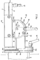
- wishbone 22 When locking clamp 25 is rotated so as to loosen the engagement of the washer on circular portion 24a, wishbone 22 may be rotated about pivot pin 23 and thus about a horizontal axis which is generally perpendicular to the planes of plate 6 and circular portion 24a.
- the screw-threaded extension of clamp 25 slides within arcuate opening 24c during rotation. Since, as described further below, table 11 is secured to wishbone 22, table 11 also is pivoted about this axis.
- the degree of rotation with respect to the vertical of wishbone 22 is shown by pointer 6b on scale 24d.
- pointer 6b indicates the degree of rotation of table 11 with respect to a vertical plane which is perpendicular to the front and rear edges of the table.
- the scale indicates the degree of side to side rotation of table 11. Locking clamp 25 is tightened to secure wishbone 22 in the desired position.
- Pivot assembly 20 further includes trunnions 30 having a semi-oval shape.
- Each trunnion 30 includes upper through holes 30a, central pivot hole 30b, and arcuate slot 30c formed through the lower periphery.
- Trunnions 30 are secured for pivoting motion, outwardly of each side arm 26 of wishbone 22, by pivot pins 31 disposed through pivot holes 30b and upper holes 27a.
- Conventional adjustable locking clamp 32 having the same structure as described for locking clamp 25 has a screw-threaded end disposed through arcuate slot 30c of each trunnion 30, and extending into screw-threaded lower holes 27b.
- Locking clamps 32 include washer elements 32a disposed adjacent the surface of trunnions 30.
- Clamps 32 may be tightened by rotation to force the washers into frictional engagement against the trunnions and securely clamp the trunnions against side arms 26 of wishbone 22, to thereby preclude the trunnions from pivoting relative to wishbone 22.
- clamps 32 may be rotated to release the frictional engagement and thereby allow trunnions 30 to pivot relative to side arms 26.
- arcuate slots 30c move along the locations where clamps 32 extend therethrough.
- Screws 34 extend through upper through holes 30a in trunnions 30 and corresponding holes 19a in brackets 19.
- Nuts 36 are disposed on the extending ends of screws 34 and thereby secure each side of table 11 to one trunnion 30.
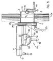
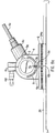
- Table 11 may be pivoted from a generally horizontal position as shown Figures 2 and 5, about a horizontal axis parallel to the front and rear ends of the table, to a position in which the table is inclined forwardly downwardly with respect to the user, as shown in Figures 1 and 11a.
- Table 11 is allowed to pivot by loosening clamps 32 as described above to allow pivoting of trunnions 30, and is fixed in any desired angle by re-tightening the clamps.
- table 11 may pivot or tilt between at least 0° and 45° relative to a vertical plane which extends substantially parallel to the front and rear edges of the table.
- Trunnions 30 may also include scale 36 formed along arcuate slots 30c to show the pivot angle at which table 11 has been fixed.
- trunnions 30 also may include locking pins 38 which fit through an opening formed in the trunnions.
- Locking pins 38 include a protrusion which extends through trunnions 30 and into one of a plurality of holes 39 formed through side arms 26 at various locations along an arc which is centred about pivot holes 30b, that is, along an arc traversed by arcuate slots 30c when trunnions 30 are pivoted.
- the locations of holes 39 correspond to predetermined preferred pivot angles for table 11.
- Locking pins 38 are biased, for example, by spring biasing such that the protrusions extend through holes 39 to thereby lock trunnions 30 at one of the predetermined pivot angles.
- locking pins 38 are pulled outwardly against the spring bias to remove the protrusions from holes 39 and thereby allow trunnions 30 to pivot. After a desired predetermined pivot angle is reached, locking pins 38 are released. If table 11 has been pivoted to one of the predetermined pivot angles, the protrusions will extend through the corresponding holes 39 and help secure trunnions 30 at the desired angle. If table 11 has not been pivoted to a predetermined pivot angle, the locking pin protrusions will simply rest against the surface of arms 26. In either case, locking clamp 32 will be re-tightened to secure table 11 in the desired position.
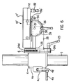
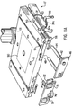
- FIG. 6 a second embodiment of the table assembly is shown as table assembly 10'.
- Assembly 10' includes table 11' which includes brackets 19' having elongated slots 19a', instead of holes 19a as in table 11.
- Slots 19a' allow the horizontal position of table 11' to be adjusted relative to trunnions 30.
- the horizontal position may be adjusted by loosening nuts 36, and pulling or pushing table 11' to a desired position with screws 34 sliding in slots 19a'.
- the nuts are re-tightened to secure table 11' in the desired position.
- table 11' may be moved away from or towards support post 3.
- table assembly 10' is identical to table assembly 10.
- a vertical height adjustment mechanism for table 11 is shown.
- the mechanism includes cylindrical casting 4 which is secured about support post 3.
- Casting 4 is split at the rear to form two "halves" which each include rearwardly extending clamping projection 4c having screw-threaded openings.
- Clamp arm 4d includes a screw-threaded projection which extends into the screw-threaded openings of clamping projections 4c. By rotating clamp arm 4d, projections 4c may be forced apart to thereby loosen the engagement of each "half" of casting 4 about support post 3. Casting 4 is then free to move along support post 3.
- Casting 4 further includes height adjustment housing 4a having a conventional pinion gear (not shown) disposed therein and rotatable handle 4b linked to the pinion gear.
- the pinion gear meshes with rack 3a which extends along the length of support post 3 and is secured at the top within collar 3e and at the bottom by an upwardly extending portion 5a of base 5 so as to be freely rotatable about post 3.
- rack 3a which extends along the length of support post 3 and is secured at the top within collar 3e and at the bottom by an upwardly extending portion 5a of base 5 so as to be freely rotatable about post 3.
- handle 4b and thus the pinion gear are rotated, the gear moves along rack 3a to thereby raise or lower casting 4 along support post 3 to adjust the vertical position of wishbone 22 relative to support post 3.
- clamp arm 4d is rotated to tighten projections 4c and secure casting 4 and thus table 11.
- support post 3 includes centrally located, vertically extending front notch 3b.
- Notch 3b is formed directly to the rear of the centre of the drill chuck.
- Casting 4 includes rectangular notch 4e formed on the interior cylindrical surface. Notch 4e is located on a horizontal axis which extends through the centre of table 22.
- Spring 3d is disposed in notch 4e and biases ball bearing 3c outwardly from notch 4e.
- ball bearing 3c is forced out of notch 3b against the spring bias.
- Ball bearing 3c is forced into notch 4e and rides along the surface of support post 3 during rotation.
- the table and casting 4 are rotated until notch 4e is opposite notch 3b.
- spring 3d biases ball bearing 3c back into notch 3b. Since the ball bearing and notches provide some resistance to rotation of casting 4, this arrangement identifies when table 11 has reached the centre location. Thereafter, handle 4d is rotated to secure casting 4 and table 11 against further rotation.
- the present invention provides a drill press in which the position of the table may be adjusted in four ways.
- Table 11 may be pivoted towards the user about a horizontal axis parallel to the front edge, or from side-to-side about a horizontal axis parallel to the side edges.
- the vertical height of the table also can be adjusted, and the table may be pivoted about a vertical axis.
- telescoping extension arm assembly 40 forming part of the invention is disclosed.
- Assembly 40 includes clamp plates 12 disposed in cut-out regions 11a as described above, and telescoping extension arm 42.
- Extension arm 42 may be clamped by clamp plates 12 in any one of six positions extending outwardly from table 11 to provide support for the extending portion of a workpiece.
- Extension arm 42 includes a pair of cylindrical or tubular extension rails 44 and support plate 46 secured to the ends of rails 44 by a pair of nuts.
- Support plate 46 has an overall rectangular shape.
- table assembly 10 includes two pair of horizontal channels 48 extending substantially parallel to the side edges of table 11 from the front and back edges of the table.
- Table assembly 10 also includes two pair of horizontal, generally circular channels 50 extending substantially parallel to the front edge of table 11 from the left and right edges of the table.
- Channels 48 and 50 have a substantially circular cross-section.
- the laterally inner channel 48 of each pair is formed entirely within table 11.
- the outer channel 48 of each pair is formed by semi-circular openings disposed in the lower surface of table 11 at the locations of cut-out portions 11a and corresponding semi-circular openings formed in the upper surface of clamp plates 12.
- the rear channel 50 of each pair is formed entirely within table 11, while the forward channel 50 of each pair is formed by openings in both table 11 and clamp plate 12.
- the diameter of channels 48 and 50 is substantially the same as the diameter of extension rails 44.
- Clamps 56 have screw-threaded ends 58 which are disposed through holes 52 and into openings 54 to adjustably secure clamp plates 12 within cut-out portions 11a. Clamps 56 may be rotated so as to loosely hold clamp plates 12 against the lower surface of table 11. Alternatively, clamps 56 may be tightened to securely hold clamp plates 12 against the lower surface of table 11. Support plate 46 is positioned outwardly of table 11 by inserting rails 44 within one pair of channels 48 or 50 when clamp plates 12 are only loosely held against table 11. When support plate 46 is positioned at any desired location relative to the edge of table 11, clamp 56 is then tightened to securely hold clamp plates 12 against the lower surface of table 11, thereby locking one extension rail 44 of arm 42 within the channel which is formed jointly by table 11 and clamp 12.
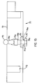
- Support plate 46 provides support for the extending portion of workpiece 100 as shown in Fig. 10b.
- Channels 48 open on both the left and right sides at the front and rear of table 11, and channels 50 open on the left and right edges of table 11.
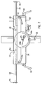
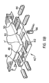
- support plate 46 can be positioned outwardly of either the left or right edge of table 11, as shown in Figs. 7 and 8.
- support plate 46 can be positioned in front of or behind table 11 on either the right or left side.
- two extension arms 42 can be secured to table 11 at any time.
- each extension arm 42 may be inserted in one pair of channels 50 so as to allow plates 46 to extend from the opposite sides of table 11, as shown in Fig. 8.
- one arm 42 can be inserted in each pair of channels 48 so as to provide plates 46 extending from each side of the front or back of table 11. Accordingly, either the effective width or the effective length of table 11 may be increased.
- Telescoping assembly 40' includes table 111 and clamp plates 112 in which both channels of each pair of channels 48 and 50 are formed by semi-circular openings disposed in the lower surface of table 111 at the locations of cut-out portions 11a and corresponding semi-circular openings formed in the upper surface of clamp plates 112.
- both rails 44 of extension arms 42 are clamped between table 111 and plates 112.
- assembly 40' is identical to assembly 40.
- telescoping extension arm assembly has been described as including clamp plates 12 and 112 which fit within cutout portions of table 11 and 111, it is understood that telescoping extension arms 42 may be clamped in other ways.
- table 11 need not include cut-out regions and may have a substantially constant cross section.
- Rails 44 may include a plurality of through holes which may be lined-up with screw-threaded through holes formed directly in the table. The screw-threaded end of the locking clamp would extend through the holes of rails 44 within table 11 to secure the rails at a desired location.
- holes 48 and 50 and rails 44 have been described as circular, other shapes could be used as well.
- the holes and rails could have a rectangular or square cross-section.
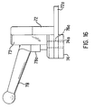
- Sliding guide fence 70 includes vertical fence wall 72 having a flat rear surface and integrally formed lower guide rail 72a which extends downwardly from fence wall 72.
- Guide rail 72a has a rectangular cross-section and extends from just in front of wall 72 to a termination point to the rear of wall 72.
- Handle mount 76 also is integrally formed with wall 72 and has a semi-oval shape. Mount 76 extends from the front of wall 72, at a location above guide rail 72a. Through hole 76a extends through mount 76 and guide rail 72a.
- Bolt 74 is square or rectangular and includes screw-threaded opening 74a.
- Bolt 74 is disposed below guide rail 72a such that opening 74a is coincident with opening 76a.
- Guide rail 72a and bolt 74 jointly have a T-shaped cross-section generally corresponding to the cross-section of T-shaped slots 13 of table 11.
- the width of guide rail 72a is about the same as the distance between opposite overhanging lips 13a and the width of bolt 74 is about the same as the width of slots 13 below lips 13a.
- Handle 78 is conventional and includes shaft 78b having a screw-threaded lower end which extends through opening 76a and into screw-threaded opening 74a of bolt 74. Handle 78 further includes cylindrical support 78a, and handle arm 78c integrally formed with and extending from support 78a. Support 78a is disposed about shaft 78b such that when arm 78c and support 78a are raised, support 78a may rotate relative to shaft 78b, thereby allowing the position of arm 78c relative to wall 72 to be adjusted. However, when arm 78c and support 78a are lowered, rotation of arm 78c and support 78a causes rotation of shaft 78b.
- guide rail 72a and loosened bolt 74 are slidingly received in one of T-shaped slots 13. Accordingly, fence wall 72 of guide fence 70 may be positioned at any location from the front to the rear edge of table 11.
- handle arm 78c and support 78a are rotated while in the lower position, thereby causing rotation of screw-threaded shaft 78b.
- bolt 74 has generally the same width as slot 13 below lips 13a and a greater width than the distance between lips 13a, bolt 74 is constrained from rotation, and is instead raised upwardly towards the lower surface of guide rail 72a and overhanging lips 13a of slot 13.
- Bolt 74 is brought into tight frictional engagement with lips 13a to thereby secure guide fence 70 at the desired location.
- bolt 74 may be loosened, allowing guide fence 70 to be moved along the surface of table 11, or removed entirely from table 12.
- Guide fence 70 further includes two vertically extending cylindrical holes 71. Holes 71 are disposed on opposite sides of mount 76, and are formed partially within the plane of wall 72 and partially within semi-cylinders 73 which extend outwardly from the front face of wall 72. Overhanging flats 75 are disposed within holes 72, and project inwardly from one side. With reference to Figure 4, clamps 80 may be disposed within holes 71. Clamps 80 include support arm 82 having upper horizontal portion 82b and vertical pole portion 82a extending downwardly from one end of portion 82b. Pole portion 82a is cylindrical and at the lower end has a decreasing diameter which expands into knob 82c. Knob 82c has an upper projecting lip which extends partially around the upper circumference.
- Pole 82a fits within hole 71 and is secured therein by rotating the upper projection lip so as to engage beneath flat 75.
- Clamps 80 also include screw-threaded shaft 84 which fits within a corresponding screw-threaded opening in upper horizontal portion 82b.
- Clamp disc 86 is secured at the lower end of shaft 84. By rotating shaft 84, clamp disc 86 may be raised or lowered.
- guide fence 70 may be slided along either one of guide slots 13 and then locked in the desired location.
- Wall 72 of fence 70 provides support for one side of a workpiece to help maintain the position during operation of the drill press.
- the position of the workpiece can be further secured by use of clamp 80 which is inserted in guide fence 70 with knob 82c secured under flat 75.
- Clamp plate 86 is then lowered into contact with a workpiece to secure the position.
- clamps 80 may be disposed directly within holes 14 disposed through the upper surface of table 11, at various locations. Holes 14 include flats or lips 14a under which knobs 82c would be disposed to secure clamps 80 in place.
- Table 11 includes a square centre opening having inwardly projecting ledges 92 around the periphery.
- Inner table 90 is removably disposed in the opening and rests upon ledges 92. This removability of inner table 90 allows the table to be replaced when worn out due to use of the drill press, without requiring that the entire table 11 be replaced. Since the centre portion of the table is most likely to wear out under long-term use, the provision of a removable centre table insert provides for economical maintenance of the drill press.
- inner table 90 includes centre circular opening 94, and four smaller screw openings 96 disposed about centre opening 94. Screw openings 96 are disposed generally equidistant along the periphery of a circle having opening 94 at the centre.
- Conventionally operating router 110 includes router bit 102 extending through an opening in disc 112 secured to the lower surface of the router.
- Disc 112 includes a plurality of screw-threaded holes 114 formed at locations which correspond to the locations of screw holes 96 in inner table 90.
- Router 110 is inverted and removably secured to inner table 90 by a plurality of screws 98 disposed through holes 96 and 114, with router bit 102 extending through circular opening 94.
- the chuck of a drill press may also be used to hold a guide pin as in a conventional pin router.
- router bit 102 will be axially aligned with the guide pin.
- such off-centring can be obtained by pivoting table 11 about the vertical axis defined by support post 3, as described above.
- inner table 90 is shown as including provisions for a router attachment, table 90 also can be provided without such an attachment.
Landscapes
- Engineering & Computer Science (AREA)
- Mechanical Engineering (AREA)
- Drilling And Boring (AREA)
- Machine Tool Units (AREA)
Priority Applications (1)
| Application Number | Priority Date | Filing Date | Title |
|---|---|---|---|
| EP02023275A EP1285723A3 (de) | 1995-09-22 | 1996-09-19 | Bohrständer mit teleskopierbarem Verlängerungsarm |
Applications Claiming Priority (2)
| Application Number | Priority Date | Filing Date | Title |
|---|---|---|---|
| US418795P | 1995-09-22 | 1995-09-22 | |
| US4187 | 1995-09-22 |
Related Child Applications (1)
| Application Number | Title | Priority Date | Filing Date |
|---|---|---|---|
| EP02023275A Division EP1285723A3 (de) | 1995-09-22 | 1996-09-19 | Bohrständer mit teleskopierbarem Verlängerungsarm |
Publications (2)
| Publication Number | Publication Date |
|---|---|
| EP0764498A2 true EP0764498A2 (de) | 1997-03-26 |
| EP0764498A3 EP0764498A3 (de) | 1997-07-23 |
Family
ID=21709592
Family Applications (1)
| Application Number | Title | Priority Date | Filing Date |
|---|---|---|---|
| EP96306829A Withdrawn EP0764498A3 (de) | 1995-09-22 | 1996-09-19 | Bohrständer mit schwenkbarem Tisch |
Country Status (3)
| Country | Link |
|---|---|
| US (2) | US5765273A (de) |
| EP (1) | EP0764498A3 (de) |
| CN (1) | CN1075410C (de) |
Cited By (6)
| Publication number | Priority date | Publication date | Assignee | Title |
|---|---|---|---|---|
| CN103658726A (zh) * | 2013-12-01 | 2014-03-26 | 苏州蓝王机床工具科技有限公司 | 一种台钻 |
| CN103802168A (zh) * | 2014-03-04 | 2014-05-21 | 成都浪度家私有限公司 | 便于调节的侧孔钻孔机物料平台 |
| CN109648117A (zh) * | 2018-12-27 | 2019-04-19 | 湖南宸睿通信科技有限公司 | 一种用于通讯设备加工的夹持式钻孔装置 |
| CN111002379A (zh) * | 2019-12-23 | 2020-04-14 | 赵洁 | 一种带有定位装置的台式钻床 |
| WO2021081503A1 (en) * | 2019-10-24 | 2021-04-29 | Jpw Industries Inc. | Drill press with modular drill press table |
| US12485509B2 (en) * | 2022-05-11 | 2025-12-02 | Eric Moreau | Clamp apparatus for drill press |
Families Citing this family (57)
| Publication number | Priority date | Publication date | Assignee | Title |
|---|---|---|---|---|
| SE504704C2 (sv) * | 1995-06-16 | 1997-04-07 | Stefan Skyllermark | Maskin för pressarbeten |
| US5960531A (en) * | 1995-09-22 | 1999-10-05 | Black & Decker Inc. | Drill press with switched reluctance motor |
| US5722308A (en) * | 1995-10-10 | 1998-03-03 | Black & Decker Inc. | Movable fence for a machine tool |
| DE19856696B4 (de) * | 1998-01-19 | 2010-07-29 | Carl Zeiss | Stativ mit einer Verstelleinheit |
| US5980167A (en) * | 1998-04-03 | 1999-11-09 | Chen; Ruey-Zon | Table fence assembly of drill press capable of facilitating accurate drilling on workpiece |
| US6719307B1 (en) | 2001-04-19 | 2004-04-13 | Chapman/Leonard Studio Equipment | Sideboard system for a camera dolly |
| CA97583S (en) | 2001-07-23 | 2002-04-26 | Qingdao D&D Electro Mechanical Technologies Co Ltd | Bench drill |
| US6705809B2 (en) | 2002-01-28 | 2004-03-16 | James T. Manos, Jr. | Drill press table |
| US7064462B2 (en) * | 2002-02-04 | 2006-06-20 | Milwaukee Electric Tool Corporation | Power tools with switched reluctance motor |
| US6857829B2 (en) * | 2002-06-10 | 2005-02-22 | Credo Technology Corporation | Drill press table accessory |
| AU2003900081A0 (en) * | 2003-01-08 | 2003-01-23 | George Moore | Drilling jig |
| FR2862682B1 (fr) * | 2003-11-26 | 2006-03-31 | Roger Mondelin Sa | Dispositif d'orientation de porte-plaques de materiau pour appareil de levage et de manutention |
| US7413389B1 (en) * | 2003-12-15 | 2008-08-19 | Huebner Randall J | Adjustable calibrated pivot-arm stop |
| FR2865952B1 (fr) * | 2004-02-10 | 2006-06-23 | Airbus France | Procede et dispositif d'usinage mecanique de panneaux flexibles en particulier de forme complexe |
| US7374373B1 (en) * | 2004-06-23 | 2008-05-20 | Joon Park | Pocket hole drilling machine |
| US20060245834A1 (en) * | 2005-04-28 | 2006-11-02 | Eastway Fair Company Limited (A Bvi Company) | Multi-orientation table for a drill press |
| JP4933775B2 (ja) * | 2005-12-02 | 2012-05-16 | 独立行政法人理化学研究所 | 微小表面形状測定プローブ |
| US20070166115A1 (en) * | 2006-01-18 | 2007-07-19 | Pemberton Donald W | Drill press |
| USD541318S1 (en) * | 2006-01-24 | 2007-04-24 | Black & Decker Inc. | Drill press |
| USD541319S1 (en) * | 2006-01-24 | 2007-04-24 | Black & Decker Inc. | Drill press |
| USD560696S1 (en) * | 2006-10-04 | 2008-01-29 | Black & Decker Inc. | Drill press handle |
| CA2925777A1 (en) * | 2007-02-07 | 2008-08-14 | Black & Decker Inc. | Router table |
| CN101380682B (zh) * | 2007-09-03 | 2012-01-25 | 苏州宝时得电动工具有限公司 | 钻床 |
| USD613779S1 (en) * | 2007-11-02 | 2010-04-13 | Husqvarna Professional Outdoor Products Inc. | Drill stand |
| USD617818S1 (en) * | 2008-01-04 | 2010-06-15 | Husqvarna Professional Outdoor Products, Inc. | Drill stand |
| USD653267S1 (en) * | 2010-03-02 | 2012-01-31 | Husqvarna Professional Outdoor Products Inc. | Drill stand base |
| CN102398056B (zh) * | 2011-12-05 | 2013-06-05 | 浙江华顺椅业有限公司 | 一种打孔机 |
| CN102699695B (zh) * | 2012-06-06 | 2014-10-01 | 行冈靖典 | 全向加工辅助架 |
| CN102990370A (zh) * | 2012-12-19 | 2013-03-27 | 南通第五机床有限公司 | 一种钻床用双工位翻转工作台 |
| CN103846468B (zh) * | 2013-04-08 | 2016-08-03 | 青岛海信模具有限公司 | 镗床三维孔加工方法 |
| US10183338B2 (en) | 2013-06-11 | 2019-01-22 | Kreg Enterprises, Inc. | Cam lock fence system and method of use |
| CN104551722B (zh) * | 2013-10-15 | 2017-05-24 | 力山工业股份有限公司 | 用于钻床的工件支撑机构 |
| CN103611963B (zh) * | 2013-11-20 | 2015-10-28 | 四川瑞迪佳源机械有限公司 | 在工件等直径位置钻孔的自动钻床及其控制方法 |
| CN103802170A (zh) * | 2014-03-04 | 2014-05-21 | 成都浪度家私有限公司 | 一种侧孔钻孔机物料台 |
| US20150266104A1 (en) * | 2014-03-19 | 2015-09-24 | Lee-Cheng Chang | Energy-Saving and Safer Drill Press |
| US10442106B2 (en) * | 2014-03-31 | 2019-10-15 | Sawstop Holding Llc | Extension rails for table saws |
| US20150283620A1 (en) * | 2014-04-02 | 2015-10-08 | Lee-Cheng Chang | Drill Press with Pivotable Table |
| USD732091S1 (en) * | 2014-04-21 | 2015-06-16 | Shanghai Sieg Machinery Co., Ltd. | Milling and drilling machine |
| USD723075S1 (en) * | 2014-07-18 | 2015-02-24 | JPW Industries, Inc. | Drill press |
| US9415502B2 (en) | 2014-07-28 | 2016-08-16 | Mark Thompson | Multi-use tool tables |
| US10428552B2 (en) * | 2015-07-30 | 2019-10-01 | William Sinclair | Post anchor |
| CN107984099B (zh) * | 2017-12-17 | 2019-11-12 | 东阳市天杨建筑工程设计有限公司 | 具有真空吸附功能的多功能激光打孔机构及其使用方法 |
| CN109079523A (zh) * | 2018-08-31 | 2018-12-25 | 无锡三立轴承股份有限公司 | 轴承加工用的立式台钻 |
| CN109227654A (zh) * | 2018-10-29 | 2019-01-18 | 镇江市鑫浩塑胶有限公司 | 一种多角度切割塑料管材的带锯装置 |
| US11072031B1 (en) * | 2019-01-21 | 2021-07-27 | Tony J. Ballew | Variable angle cutting deck for metal cutting chop saws |
| CN110961680A (zh) * | 2019-11-15 | 2020-04-07 | 嘉善瑞佳运动器材有限公司 | 一种钻孔设备 |
| CN110788398A (zh) * | 2019-11-27 | 2020-02-14 | 国网河南省电力公司南阳供电公司 | 一种位置可调的电锯安装座 |
| CN111531193B (zh) * | 2020-05-08 | 2021-06-18 | 玉环周浪汽配厂 | 一种圆盘工件钻孔加工用可调式台钻 |
| CN112025378B (zh) * | 2020-09-15 | 2021-07-23 | 山东工业职业学院 | 一种机械制造专用钻孔装置 |
| CN114871465B (zh) * | 2020-10-28 | 2024-08-06 | 扬州蔚来机械装备制造有限责任公司 | 一种多工位高效率的台式钻床 |
| USD970562S1 (en) * | 2021-01-22 | 2022-11-22 | Scheppach Gmbh | Bench drilling machine |
| JP3234112U (ja) * | 2020-12-04 | 2021-09-24 | ファナック株式会社 | 工作機械 |
| CN113001181B (zh) * | 2021-02-27 | 2022-05-31 | 山东凯帝斯工业系统有限公司 | 汽车转向器输入轴的扭杆对中打孔压销装置和方法 |
| CN113353564A (zh) * | 2021-05-20 | 2021-09-07 | 广州鑫泓设备设计有限公司 | 物料传输监控校正系统 |
| US11465217B1 (en) * | 2021-08-18 | 2022-10-11 | Woodpeckers, Llc | Method and apparatus for using a portable drill |
| USD975516S1 (en) | 2021-08-18 | 2023-01-17 | Woodpeckers, Llc | Drill guide |
| US12491568B2 (en) | 2022-03-16 | 2025-12-09 | Woodpeckers, Llc | Machining jig for creating compound angles |
Citations (1)
| Publication number | Priority date | Publication date | Assignee | Title |
|---|---|---|---|---|
| US4572492A (en) * | 1982-07-16 | 1986-02-25 | Sansin Kiko Co. Ltd. | XYZ Vise |
Family Cites Families (77)
| Publication number | Priority date | Publication date | Assignee | Title |
|---|---|---|---|---|
| US324759A (en) * | 1885-08-18 | Drilling-machine | ||
| US54248A (en) * | 1866-04-24 | Improvement in machine-drills | ||
| US1895106A (en) * | 1933-01-24 | Doweling machine | ||
| US657033A (en) * | 1900-05-19 | 1900-08-28 | Charles H Sanford | Table. |
| US1564876A (en) * | 1921-08-08 | 1925-12-08 | Greenlee Bros & Co | Boring machine |
| US1427277A (en) * | 1921-12-31 | 1922-08-29 | Fetter Edward | Self-healing tube |
| US1864840A (en) * | 1928-11-26 | 1932-06-28 | Lehner Louis | Adjustable stock support bracket |
| FR715868A (fr) * | 1931-04-22 | 1931-12-10 | Machine-outil pour percage, taraudage, filetage et opérations analogues | |
| US1992514A (en) * | 1932-11-16 | 1935-02-26 | Firestone Tire & Rubber Co | Method of making an inner tube |
| US2122966A (en) * | 1936-08-31 | 1938-07-05 | Delta Mfg Co | Drill press table operating means |
| US2383201A (en) * | 1942-03-02 | 1945-08-21 | Edward Q Kruchten | Work-holding and positioning means |
| US2340054A (en) * | 1942-03-04 | 1944-01-25 | Walter R Grunewald | Drill press |
| US2464690A (en) * | 1945-09-26 | 1949-03-15 | Ketchem Roy | Reading stand |
| US2668568A (en) * | 1951-11-30 | 1954-02-09 | Lena M Budd | Edger and finisher |
| NL240479A (de) * | 1958-06-23 | |||
| US3246612A (en) * | 1963-12-11 | 1966-04-19 | Ballas George Charles | Adjustable table |
| US3301547A (en) * | 1964-06-18 | 1967-01-31 | Jordan Charles Ray | Means for handling radiators for repairs |
| US3329043A (en) * | 1965-05-17 | 1967-07-04 | Robert M Stanford | Drilling machine for bowling balls |
| US3359836A (en) * | 1965-06-09 | 1967-12-26 | Oscar W Jalava | Drill press work-holding apparatus |
| BE672057A (de) * | 1965-11-08 | 1966-03-01 | ||
| US3382740A (en) * | 1965-12-29 | 1968-05-14 | Russell P. Lotta | Ball drilling machine |
| US3464295A (en) * | 1966-08-29 | 1969-09-02 | Jacque K Gallion | Drilling device |
| US3530513A (en) * | 1967-09-08 | 1970-09-29 | Weber Dental Mfg Co | Dental bowl support construction |
| US3474691A (en) * | 1968-01-29 | 1969-10-28 | Louis Levin & Son Inc | Universal angular indexing table |
| FR1600704A (de) * | 1968-12-31 | 1970-07-27 | ||
| US3782847A (en) * | 1971-12-29 | 1974-01-01 | L Kulzer | Method and apparatus for reconditioning cylinder heads |
| US3794089A (en) * | 1972-08-28 | 1974-02-26 | G Morse | Positioning coupling for a table bracket |
| US3822961A (en) * | 1972-11-21 | 1974-07-09 | Mc Graw Edison Co | Variable speed drill press |
| US3837757A (en) * | 1973-05-29 | 1974-09-24 | A Levine | Drill press |
| US4186916A (en) * | 1978-09-18 | 1980-02-05 | Salisbury Special Tool | Precision workpiece positioning means for machine tools |
| US4179231A (en) * | 1978-10-30 | 1979-12-18 | Hadden Terence B | Drill guide |
| NL8000203A (nl) * | 1980-01-14 | 1981-08-17 | Buitendijk Tech Bv | Inrichting voor het ondersteunen en verstellen van te bewerken werkstukken. |
| US4350193A (en) * | 1980-05-01 | 1982-09-21 | Central Quality Industries, Inc. | Power tool accessory table |
| IT8021765V0 (it) * | 1980-05-07 | 1980-05-07 | Zinken Italiana | Macchina combinata piallatrice, comprendente utensili per segare, fresare e assoggettare a mortasa. |
| US4375827A (en) * | 1980-12-03 | 1983-03-08 | Ranko Ignjatic | Workbench table top clamping device |
| US4527942A (en) * | 1982-08-25 | 1985-07-09 | Intest Corporation | Electronic test head positioner for test systems |
| EP0237698B1 (de) * | 1982-08-25 | 1992-04-22 | InTest Corporation | Einstellvorrichtung für elektronische Testköpfe |
| US4502457A (en) * | 1982-08-27 | 1985-03-05 | Raul C. Montoya | Universal multiple angle work piece holder with multiple tool conversion features |
| US4516612A (en) * | 1982-09-03 | 1985-05-14 | Wiley Edward R | Multipurpose table saw |
| US4521144A (en) * | 1983-08-02 | 1985-06-04 | Ginter Carl A | Quill stop device |
| US4693656A (en) * | 1983-09-01 | 1987-09-15 | 5W Enterprises, Inc. | Quick adjusting nut |
| FR2585276B2 (fr) * | 1985-07-26 | 1987-11-13 | Sateco Sarl | Machine executant diverses operations d'usinage telles que tournage, fraisage, alesage |
| DE3666375D1 (en) * | 1985-10-30 | 1989-11-23 | Werkzeug Gmbh | Work table |
| US4973015A (en) * | 1987-09-17 | 1990-11-27 | Schlumberger Technologies, Inc. | Manipulator apparatus for test head support and orientation |
| US4909683A (en) * | 1987-10-13 | 1990-03-20 | Milwaukee Machine Tool | Position indicating mechanism |
| FR2649632A2 (fr) * | 1988-07-25 | 1991-01-18 | Fournel Paul | Structure polyvalente pour tous travaux d'usinage principalement de materiaux tendres |
| DE3835717A1 (de) * | 1988-10-20 | 1990-04-26 | Nestler Albert Verkauf | Arbeitstisch mit verstellbarer tischplatte |
| US4887653A (en) * | 1988-11-04 | 1989-12-19 | Thomas Alvin R | Power tool attachment for table saws |
| DE3910826C1 (de) * | 1989-04-04 | 1990-11-08 | Werkzeug Gmbh, 5441 Weibern, De | |
| US4978261A (en) * | 1989-12-08 | 1990-12-18 | Wright Iii Charles O | Quill stop |
| US5004029A (en) * | 1990-04-16 | 1991-04-02 | Garner William C | Saw table apparatus |
| US5061124A (en) * | 1990-07-27 | 1991-10-29 | Chen Chao Yang | Drilling machine |
| DE4109028A1 (de) * | 1991-03-20 | 1992-09-24 | Peddinghaus Rolf | Vorrichtung zum positionieren von werkstuecken |
| US5252010A (en) * | 1991-03-22 | 1993-10-12 | Technical Manufacturing Corporation | Adjustable stop assembly for a press |
| US5115847A (en) * | 1991-04-19 | 1992-05-26 | Taber Tarrell L | Adjustable support apparatus for table saws |
| US5102270A (en) * | 1991-05-24 | 1992-04-07 | James Warren | Drill press clamp |
| JPH04368203A (ja) * | 1991-06-17 | 1992-12-21 | Toyota Motor Corp | 液封タイヤ |
| US5098235A (en) * | 1991-08-09 | 1992-03-24 | Skil Corporation | Bit storage means for drill press |
| US5127775A (en) * | 1991-11-01 | 1992-07-07 | Smith & Wesson Corp. | Fail safe stop for a drill press control device |
| DE59302201D1 (de) * | 1992-05-27 | 1996-05-15 | Woelfle Johannes Peter | Multifunktionaler arbeitsbock |
| US5193598A (en) * | 1992-06-23 | 1993-03-16 | Estrem Jim J | Portable support stand attachable to a sawhorse |
| DE4305260A1 (de) * | 1993-02-20 | 1994-08-25 | Haeberle Gerhard Fa | Werkstückspannvorrichtung |
| DE4311965A1 (de) * | 1993-04-10 | 1994-10-13 | Klaus Dr Ing Thormeier | Werkbank, insbesondere als Lehrmittel in der Form einer ergonomisch gestalteten Mehrzweck-Werkbank |
| US5634748A (en) * | 1993-05-19 | 1997-06-03 | Ryobi Limited | Drill press having a movable head and a tilt table |
| US5318392A (en) * | 1993-08-09 | 1994-06-07 | S-B Power Tool Company | Adjustable fence for drill press |
| US5473968A (en) * | 1993-08-25 | 1995-12-12 | Tapco Products Company, Inc. | Tilting saw table |
| US5431206A (en) * | 1993-10-25 | 1995-07-11 | Mcallister; Michael J. | Portable workstation |
| US5398740A (en) * | 1993-11-12 | 1995-03-21 | Miller; Manford B. | Power tool table with adjustable tool mounting plate insert and related method |
| US5379816A (en) * | 1993-11-22 | 1995-01-10 | Charlton; Russell T. | Auxiliary support device for a power tool |
| US5363893A (en) * | 1993-12-13 | 1994-11-15 | Grochowicz Sebastian F | Table saw extension apparatus |
| US5479972A (en) * | 1994-12-09 | 1996-01-02 | Photo Sculptures, Inc. | Extension table for a table saw |
| US5533844A (en) * | 1994-11-15 | 1996-07-09 | Ekleberry; Donald A. | Travelling platen with extended axis |
| US5516089A (en) * | 1994-12-30 | 1996-05-14 | Gerber Systems Corporation | Adjustable workpiece locating unit |
| US5547319A (en) * | 1995-04-24 | 1996-08-20 | American Machine & Tool Company, Inc. | Machine tool apparatus having a work piece support table supported by an articulating arm |
| US5526856A (en) * | 1995-06-27 | 1996-06-18 | Pedri; Attilio | Device for supporting workpiece for a portable power tool |
| US5722308A (en) * | 1995-10-10 | 1998-03-03 | Black & Decker Inc. | Movable fence for a machine tool |
| US5725037A (en) * | 1996-09-24 | 1998-03-10 | Faulhaber; Kenneth P. | Mobile tool storage box and work bench combination |
-
1996
- 1996-09-16 US US08/714,714 patent/US5765273A/en not_active Expired - Fee Related
- 1996-09-19 EP EP96306829A patent/EP0764498A3/de not_active Withdrawn
- 1996-09-22 CN CN96121128A patent/CN1075410C/zh not_active Expired - Fee Related
-
1997
- 1997-11-25 US US08/978,355 patent/US5924827A/en not_active Expired - Fee Related
Patent Citations (1)
| Publication number | Priority date | Publication date | Assignee | Title |
|---|---|---|---|---|
| US4572492A (en) * | 1982-07-16 | 1986-02-25 | Sansin Kiko Co. Ltd. | XYZ Vise |
Cited By (6)
| Publication number | Priority date | Publication date | Assignee | Title |
|---|---|---|---|---|
| CN103658726A (zh) * | 2013-12-01 | 2014-03-26 | 苏州蓝王机床工具科技有限公司 | 一种台钻 |
| CN103802168A (zh) * | 2014-03-04 | 2014-05-21 | 成都浪度家私有限公司 | 便于调节的侧孔钻孔机物料平台 |
| CN109648117A (zh) * | 2018-12-27 | 2019-04-19 | 湖南宸睿通信科技有限公司 | 一种用于通讯设备加工的夹持式钻孔装置 |
| WO2021081503A1 (en) * | 2019-10-24 | 2021-04-29 | Jpw Industries Inc. | Drill press with modular drill press table |
| CN111002379A (zh) * | 2019-12-23 | 2020-04-14 | 赵洁 | 一种带有定位装置的台式钻床 |
| US12485509B2 (en) * | 2022-05-11 | 2025-12-02 | Eric Moreau | Clamp apparatus for drill press |
Also Published As
| Publication number | Publication date |
|---|---|
| EP0764498A3 (de) | 1997-07-23 |
| CN1157199A (zh) | 1997-08-20 |
| US5765273A (en) | 1998-06-16 |
| CN1075410C (zh) | 2001-11-28 |
| US5924827A (en) | 1999-07-20 |
Similar Documents
| Publication | Publication Date | Title |
|---|---|---|
| US5765273A (en) | Drill press having pivotable table | |
| US5960531A (en) | Drill press with switched reluctance motor | |
| US5634748A (en) | Drill press having a movable head and a tilt table | |
| US7367253B2 (en) | Cutting assembly having multiple turntable locking mechanisms | |
| AU2002240365B2 (en) | Fence with a fine adjustment mechanism | |
| EP0262208B1 (de) | Vorrichtung zum befestigen einer schiene oder dergleichen an eine fläche | |
| US9399307B2 (en) | Router table | |
| US5460070A (en) | Fence for table saws | |
| US20210121994A1 (en) | Drill press with modular drill press table | |
| US7121932B2 (en) | Portable drill sharpener | |
| US4216560A (en) | Deburring apparatus | |
| CA2124141A1 (en) | Saw table with compound movement of saw | |
| US7287453B2 (en) | Woodworking table with an auxiliary device | |
| JPS59138401A (ja) | 鋸台 | |
| JPH06502600A (ja) | 木工フライス盤用保護およびガイド装置 | |
| KR100435331B1 (ko) | 밀링 머신용 지그 | |
| US20070039441A1 (en) | Multi-function power saw | |
| US6095726A (en) | Coping apparatus | |
| EP1285723A2 (de) | Bohrständer mit teleskopierbarem Verlängerungsarm | |
| EP0875335A2 (de) | Bohrständer mit geschaltetem Reluktanzmotor | |
| JPS6327684A (ja) | 蝶番 | |
| JPH072321B2 (ja) | テーブルソー | |
| CA2136489A1 (en) | Pin router apparatus | |
| KR19980065801U (ko) | 차량 조립용 가변 지그 유니트 | |
| US20030190202A1 (en) | Coping apparatus |
Legal Events
| Date | Code | Title | Description |
|---|---|---|---|
| PUAI | Public reference made under article 153(3) epc to a published international application that has entered the european phase |
Free format text: ORIGINAL CODE: 0009012 |
|
| AK | Designated contracting states |
Kind code of ref document: A2 Designated state(s): DE FR GB |
|
| PUAL | Search report despatched |
Free format text: ORIGINAL CODE: 0009013 |
|
| AK | Designated contracting states |
Kind code of ref document: A3 Designated state(s): DE FR GB |
|
| 17P | Request for examination filed |
Effective date: 19971223 |
|
| 17Q | First examination report despatched |
Effective date: 20010116 |
|
| GRAH | Despatch of communication of intention to grant a patent |
Free format text: ORIGINAL CODE: EPIDOS IGRA |
|
| STAA | Information on the status of an ep patent application or granted ep patent |
Free format text: STATUS: THE APPLICATION IS DEEMED TO BE WITHDRAWN |
|
| 18D | Application deemed to be withdrawn |
Effective date: 20030401 |