EP0764771A2 - Selbstzündende Brennkraftmaschine - Google Patents
Selbstzündende Brennkraftmaschine Download PDFInfo
- Publication number
- EP0764771A2 EP0764771A2 EP96115172A EP96115172A EP0764771A2 EP 0764771 A2 EP0764771 A2 EP 0764771A2 EP 96115172 A EP96115172 A EP 96115172A EP 96115172 A EP96115172 A EP 96115172A EP 0764771 A2 EP0764771 A2 EP 0764771A2
- Authority
- EP
- European Patent Office
- Prior art keywords
- fuel ratio
- air
- fuel
- mean value
- compression ignition
- Prior art date
- Legal status (The legal status is an assumption and is not a legal conclusion. Google has not performed a legal analysis and makes no representation as to the accuracy of the status listed.)
- Withdrawn
Links
Images





Classifications
-
- F—MECHANICAL ENGINEERING; LIGHTING; HEATING; WEAPONS; BLASTING
- F02—COMBUSTION ENGINES; HOT-GAS OR COMBUSTION-PRODUCT ENGINE PLANTS
- F02D—CONTROLLING COMBUSTION ENGINES
- F02D41/00—Electrical control of supply of combustible mixture or its constituents
- F02D41/0025—Controlling engines characterised by use of non-liquid fuels, pluralities of fuels, or non-fuel substances added to the combustible mixtures
- F02D41/0047—Controlling exhaust gas recirculation [EGR]
- F02D41/005—Controlling exhaust gas recirculation [EGR] according to engine operating conditions
-
- B—PERFORMING OPERATIONS; TRANSPORTING
- B01—PHYSICAL OR CHEMICAL PROCESSES OR APPARATUS IN GENERAL
- B01D—SEPARATION
- B01D53/00—Separation of gases or vapours; Recovering vapours of volatile solvents from gases; Chemical or biological purification of waste gases, e.g. engine exhaust gases, smoke, fumes, flue gases, aerosols
- B01D53/34—Chemical or biological purification of waste gases
- B01D53/92—Chemical or biological purification of waste gases of engine exhaust gases
- B01D53/94—Chemical or biological purification of waste gases of engine exhaust gases by catalytic processes
- B01D53/9481—Catalyst preceded by an adsorption device without catalytic function for temporary storage of contaminants, e.g. during cold start
-
- B—PERFORMING OPERATIONS; TRANSPORTING
- B01—PHYSICAL OR CHEMICAL PROCESSES OR APPARATUS IN GENERAL
- B01D—SEPARATION
- B01D53/00—Separation of gases or vapours; Recovering vapours of volatile solvents from gases; Chemical or biological purification of waste gases, e.g. engine exhaust gases, smoke, fumes, flue gases, aerosols
- B01D53/34—Chemical or biological purification of waste gases
- B01D53/92—Chemical or biological purification of waste gases of engine exhaust gases
- B01D53/94—Chemical or biological purification of waste gases of engine exhaust gases by catalytic processes
- B01D53/9495—Controlling the catalytic process
-
- F—MECHANICAL ENGINEERING; LIGHTING; HEATING; WEAPONS; BLASTING
- F01—MACHINES OR ENGINES IN GENERAL; ENGINE PLANTS IN GENERAL; STEAM ENGINES
- F01N—GAS-FLOW SILENCERS OR EXHAUST APPARATUS FOR MACHINES OR ENGINES IN GENERAL; GAS-FLOW SILENCERS OR EXHAUST APPARATUS FOR INTERNAL-COMBUSTION ENGINES
- F01N3/00—Exhaust or silencing apparatus having means for purifying, rendering innocuous, or otherwise treating exhaust
- F01N3/08—Exhaust or silencing apparatus having means for purifying, rendering innocuous, or otherwise treating exhaust for rendering innocuous
- F01N3/0807—Exhaust or silencing apparatus having means for purifying, rendering innocuous, or otherwise treating exhaust for rendering innocuous by using absorbents or adsorbents
- F01N3/0828—Exhaust or silencing apparatus having means for purifying, rendering innocuous, or otherwise treating exhaust for rendering innocuous by using absorbents or adsorbents characterised by the absorbed or adsorbed substances
- F01N3/0842—Nitrogen oxides
-
- F—MECHANICAL ENGINEERING; LIGHTING; HEATING; WEAPONS; BLASTING
- F01—MACHINES OR ENGINES IN GENERAL; ENGINE PLANTS IN GENERAL; STEAM ENGINES
- F01N—GAS-FLOW SILENCERS OR EXHAUST APPARATUS FOR MACHINES OR ENGINES IN GENERAL; GAS-FLOW SILENCERS OR EXHAUST APPARATUS FOR INTERNAL-COMBUSTION ENGINES
- F01N3/00—Exhaust or silencing apparatus having means for purifying, rendering innocuous, or otherwise treating exhaust
- F01N3/08—Exhaust or silencing apparatus having means for purifying, rendering innocuous, or otherwise treating exhaust for rendering innocuous
- F01N3/0807—Exhaust or silencing apparatus having means for purifying, rendering innocuous, or otherwise treating exhaust for rendering innocuous by using absorbents or adsorbents
- F01N3/0871—Exhaust or silencing apparatus having means for purifying, rendering innocuous, or otherwise treating exhaust for rendering innocuous by using absorbents or adsorbents using means for controlling, e.g. purging, the absorbents or adsorbents
-
- F—MECHANICAL ENGINEERING; LIGHTING; HEATING; WEAPONS; BLASTING
- F02—COMBUSTION ENGINES; HOT-GAS OR COMBUSTION-PRODUCT ENGINE PLANTS
- F02D—CONTROLLING COMBUSTION ENGINES
- F02D41/00—Electrical control of supply of combustible mixture or its constituents
- F02D41/02—Circuit arrangements for generating control signals
- F02D41/021—Introducing corrections for particular conditions exterior to the engine
- F02D41/0235—Introducing corrections for particular conditions exterior to the engine in relation with the state of the exhaust gas treating apparatus
- F02D41/027—Introducing corrections for particular conditions exterior to the engine in relation with the state of the exhaust gas treating apparatus to purge or regenerate the exhaust gas treating apparatus
- F02D41/0275—Introducing corrections for particular conditions exterior to the engine in relation with the state of the exhaust gas treating apparatus to purge or regenerate the exhaust gas treating apparatus the exhaust gas treating apparatus being a NOx trap or adsorbent
-
- F—MECHANICAL ENGINEERING; LIGHTING; HEATING; WEAPONS; BLASTING
- F02—COMBUSTION ENGINES; HOT-GAS OR COMBUSTION-PRODUCT ENGINE PLANTS
- F02D—CONTROLLING COMBUSTION ENGINES
- F02D41/00—Electrical control of supply of combustible mixture or its constituents
- F02D41/30—Controlling fuel injection
- F02D41/38—Controlling fuel injection of the high pressure type
-
- F—MECHANICAL ENGINEERING; LIGHTING; HEATING; WEAPONS; BLASTING
- F02—COMBUSTION ENGINES; HOT-GAS OR COMBUSTION-PRODUCT ENGINE PLANTS
- F02B—INTERNAL-COMBUSTION PISTON ENGINES; COMBUSTION ENGINES IN GENERAL
- F02B3/00—Engines characterised by air compression and subsequent fuel addition
- F02B3/06—Engines characterised by air compression and subsequent fuel addition with compression ignition
-
- F—MECHANICAL ENGINEERING; LIGHTING; HEATING; WEAPONS; BLASTING
- F02—COMBUSTION ENGINES; HOT-GAS OR COMBUSTION-PRODUCT ENGINE PLANTS
- F02D—CONTROLLING COMBUSTION ENGINES
- F02D41/00—Electrical control of supply of combustible mixture or its constituents
- F02D41/0002—Controlling intake air
- F02D2041/0022—Controlling intake air for diesel engines by throttle control
-
- F—MECHANICAL ENGINEERING; LIGHTING; HEATING; WEAPONS; BLASTING
- F02—COMBUSTION ENGINES; HOT-GAS OR COMBUSTION-PRODUCT ENGINE PLANTS
- F02D—CONTROLLING COMBUSTION ENGINES
- F02D2200/00—Input parameters for engine control
- F02D2200/02—Input parameters for engine control the parameters being related to the engine
- F02D2200/06—Fuel or fuel supply system parameters
- F02D2200/0611—Fuel type, fuel composition or fuel quality
- F02D2200/0612—Fuel type, fuel composition or fuel quality determined by estimation
-
- F—MECHANICAL ENGINEERING; LIGHTING; HEATING; WEAPONS; BLASTING
- F02—COMBUSTION ENGINES; HOT-GAS OR COMBUSTION-PRODUCT ENGINE PLANTS
- F02D—CONTROLLING COMBUSTION ENGINES
- F02D2250/00—Engine control related to specific problems or objectives
- F02D2250/32—Air-fuel ratio control in a diesel engine
-
- F—MECHANICAL ENGINEERING; LIGHTING; HEATING; WEAPONS; BLASTING
- F02—COMBUSTION ENGINES; HOT-GAS OR COMBUSTION-PRODUCT ENGINE PLANTS
- F02M—SUPPLYING COMBUSTION ENGINES IN GENERAL WITH COMBUSTIBLE MIXTURES OR CONSTITUENTS THEREOF
- F02M26/00—Engine-pertinent apparatus for adding exhaust gases to combustion-air, main fuel or fuel-air mixture, e.g. by exhaust gas recirculation [EGR] systems
- F02M26/13—Arrangement or layout of EGR passages, e.g. in relation to specific engine parts or for incorporation of accessories
-
- Y—GENERAL TAGGING OF NEW TECHNOLOGICAL DEVELOPMENTS; GENERAL TAGGING OF CROSS-SECTIONAL TECHNOLOGIES SPANNING OVER SEVERAL SECTIONS OF THE IPC; TECHNICAL SUBJECTS COVERED BY FORMER USPC CROSS-REFERENCE ART COLLECTIONS [XRACs] AND DIGESTS
- Y02—TECHNOLOGIES OR APPLICATIONS FOR MITIGATION OR ADAPTATION AGAINST CLIMATE CHANGE
- Y02T—CLIMATE CHANGE MITIGATION TECHNOLOGIES RELATED TO TRANSPORTATION
- Y02T10/00—Road transport of goods or passengers
- Y02T10/10—Internal combustion engine [ICE] based vehicles
- Y02T10/40—Engine management systems
Definitions
- the present invention relates to a compression ignition type engine.
- a compression ignition type engine which provides in the engine exhaust passage an NO x absorbent which absorbs NO x when the air-fuel ratio of the inflowing exhaust gas flowing into the NO x absorbent is lean and releases the absorbed NO x when the air-fuel ratio of the inflowing exhaust gas is the stoichiometric air-fuel ratio or rich.
- the mean value of the air-fuel ratio in the combustion chamber is normally maintained lean, and the NO x produced in the combustion chamber is absorbed in the NO x absorbent.
- the mean value of the air-fuel ratio in the combustion chamber is changed from lean to rich when the NO x is to be released from the NO x absorbent (see international Publication WO93/07363).
- An object of the present invention is to provide a compression ignition type engine capable of making the mean value of the air-fuel ratio in the combustion chamber a rich air-fuel ratio or the stoichiometric air-fuel ratio to release NO x from the NO x absorbent while preventing the generation of soot.
- a compression ignition type engine having an exhaust passage, comprising an NO x absorbent arranged in the exhaust passage, the NO x absorbent absorbing NO x when an air-fuel ratio of exhaust gas flowing into the NO x absorbent is lean and releasing the absorbed NO x when the air-fuel ratio of exhaust gas is one of a rich air-fuel ratio and the stoichiometric air-fuel ratio, and air-fuel ratio control means for normally maintaining the mean value of the air-fuel ratio in a combustion chamber of the engine at a lean air-fuel ratio and changing over the mean value of the air-fuel ratio from a lean air-fuel ratio to one of a rich air-fuel ratio and the stoichiometric air-fuel ratio when NO x should be released from the NO x absorbent, a fuel containing oxygen therein being used at least when the mean value of the air-fuel ratio is made one of a rich air-fuel ratio and the stoichiometric air-fuel ratio.
- Fig. 1 is an overview of a compression ignition type engine
- Figs. 2A and 2B are views of the fuel injection amount Q
- Fig. 3 is a view of the target air-fuel ratio (A/F) 0
- Fig. 4 is a graph of the opening of an EGR control valve and throttle valve
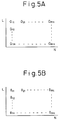
- Figs. 5A and 5B are views of maps of the opening G of the EGR control valve and the opening ⁇ of the throttle valve
- Fig. 6 is a graph of the output of an air-fuel ratio sensor
- Figs. 7A and 7B are views explaining the absorption and release action of the NO x absorbent
- Fig. 1 is an overview of a compression ignition type engine
- Figs. 2A and 2B are views of the fuel injection amount Q
- Fig. 3 is a view of the target air-fuel ratio (A/F) 0
- Fig. 4 is a graph of the opening of an EGR control valve and throttle valve
- Figs. 5A and 5B are views
- FIG. 8 is a view of a map of the NO x absorption amount A;
- Fig. 9 is a time chart of a first embodiment of the NO x releasing control;
- Fig. 10 is a time chart of a second embodiment of the NO x releasing control;
- Fig. 11 is a flow chart of the operating control;
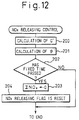
- Fig. 12 is a flow chart of the NO x releasing control;
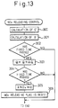
- Fig. 13 is a flow chart of another embodiment of the NO x releasing control;
- Fig. 14 is a flow chart of another embodiment of the operating control.
- 1 is the body of an in-cylinder injection type compression ignition type engine
- 2 is a piston
- 3 is a combustion chamber
- 4 is a fuel injector for directly injecting fuel toward the inside of the combustion chamber 3
- 5 is an intake valve
- 6 is an intake port
- 7 is an exhaust valve
- 8 is an exhaust port.
- the intake port 6 is connected through a corresponding intake pipe 9 to a surge tank 10, while the surge tank 10 is connected through an intake duct 11 to an air cleaner 12.
- a throttle valve 14 which is controlled to open and close by a drive motor 13.
- the exhaust port 8 is connected through an exhaust manifold 15 and exhaust pipe 16 to a casing 18 housing an NO x absorbent 17.
- the exhaust manifold 15 and the surge tank 10 are connected with each other by an exhaust gas recirculation (EGR) passage 19.
- EGR exhaust gas recirculation
- the fuel injector 4 is connected to a fuel injection pump 21 driven by the engine. Fuel discharged from the fuel injection pump 21 is supplied to the fuel injector 4.
- This fuel injection pump 21 is controlled in its discharge by an output signal of an electronic control unit 30 and therefore the amount of fuel injected from the fuel injector 4 is also controlled by the output signal of the electronic control unit 30.
- the electronic control unit 30 is comprised of a digital computer which is provided with a read only memory (ROM) 32, random access memory (RAM) 33, microprocessor (CPU) 34, input port 35, and output port 36 all connected with each other by a bidirectional bus 31.
- ROM read only memory
- RAM random access memory
- CPU microprocessor
- input port 35 input port 35
- output port 36 output port 36
- ROM read only memory
- RAM random access memory
- CPU microprocessor
- the inport port 35 has connected to it an engine speed sensor 25 which generates an output pulse expressing the engine speed.
- the output port 36 is connected through a corresponding drive circuit 38 to a drive motor 13, the EGR control valve 20, and the fuel injection pump 21.
- a compression ignition type engine generally is operated in a state of a considerably large rate of excess air, that is, in a state with a considerably lean mean value of the air-fuel ratio in the combustion chamber. So long as the mean value of the air-fuel ratio in the combustion chamber is considerably lean in this way, however, a sufficiently high engine output cannot be obtained. To raise the engine output, it is necessary to bring the mean value of the air-fuel ratio in the combustion chamber as close to the stoichiometric air-fuel ratio as possible.
- the fuel spray disperses homogeneously inside the combustion chamber, so even if the mean value of the air-fuel ratio in the combustion chamber is made the stoichiometric air-fuel ratio, no soot will be produced, but in this case an explosive combustion is caused, so this method cannot be adopted.
- the present invention use is made of fuel containing oxygen as the fuel injected from the fuel injector 4 to the combustion chamber 3 so as to give a good combustion without the production of soot even if making the mean value of the air-fuel ratio in the combustion chamber close to the stoichiometric air-fuel ratio.
- the fuel containing oxygen use may be made of a fuel containing oxygen atoms in the hydrocarbon molecules themselves or fuel obtainined by adding an additive containing oxygen. Whichever fuel is used, oxygen ends up being contained in the fuel injected from the fuel injector 4.
- Figure 2A shows the relationship between the injection amount Q of the fuel containing oxygen and the amount of depression L of the accelerator pedal 23 at the time of a constant engine speed.
- the fuel injection amount Q increases the greater the amount of depression L of the accelerator pedal 23, that is, the higher the engine load.
- the fuel injection amount Q is also a function of the engine speed N, not just the amount of depression L of the accelerator pedal 23. Therefore, the fuel injection amount Q is stored in the ROM 32 in advance in the form of the map shown in Fig. 2B.
- Figure 3 shows the relationship between the amount of depression L of the accelerator pedal 23 and the target value of the mean value of the air-fuel ratio in the combustion chamber 3, that is, the target air-fuel ratio (A/F) 0 .
- This target air-fuel ratio (A/F) 0 shows the lower limit of the air-fuel ratio which does not produce much soot. It may be seen that this target air-fuel ratio (A/F) 0 is somewhat to the lean side when the engine load is low, but becomes considerably close to the stoichiometric air-fuel ratio when the engine load rises to a certain degree.
- one method has is to increase the amount of EGR gas recirculated the lower the engine load so as to reduce the amount of intake air supplied into the combustion chamber 3, while another method is to reduce the opening of the throttle valve 14 the lower the engine load so as to decrease the amount of intake air supplied in the combustion chamber 3.
- Another method is to perform these operations simultaneously.
- the solid lines in Fig. 4 show the case of simultaneous use of these methods. In this case, as shown by the solid lines in Fig.
- the opening of the EGR control valve 20 and the opening of the throttle valve 14 are functions of not only the amount of depression L of the accelerator pedal 23, but also the engine speed N. Accordingly, the opening G of the EGR control valve 14 and the opening ⁇ of the throttle valve 14 are stored in advance in the ROM 32 in the form of the maps shown in Fig. 5A and Fig. 5B, respectively.
- the mean value of the air-fuel ratio in the combustion chamber 3 becomes the target air-fuel ratio (A/F) 0 shown in Fig. 3.
- the air-fuel ratio in the spray region of the fuel injected from the fuel injector 4 would become extremely rich and therefore a large amount of soot would be produced.
- the fuel contains oxygen
- oxygen is homogeneously dispersed in the fuel spray and therefore the fuel particles are burned in the presence of sufficient oxygen and it is possible to obtain good combustion without production of soot.
- the opening G of the EGR control valve 20 shown in Fig. 5A and the opening ⁇ of the throttle valve 14 shown in Fig. 5B are of course set in consideration of the amount of oxygen contained in the fuel so that the air-fuel ratio in the combustion chamber 3 becomes the target air-fuel ratio (A/F) 0 .
- Fig. 6 shows the relationship between the output voltage V of the air-fuel ratio sensor 22 and the mean value of the air-fuel ratio A/F in the combustion chamber 3. Accordingly, it is seen that it is possible to detect the mean value of the air-fuel ratio A/F in the combustion chamber 3 by the air-fuel ratio sensor 22.
- the fuel injection amount Q When controlling the mean value of the air-fuel ratio A/F by the fuel injection amount Q, when the mean value of the air-fuel ratio A/F detected by the air-fuel ratio sensor 22 is larger than the target air-fuel ratio (A/F) 0 , the fuel injection amount Q is increased, while when the mean value of the air-fuel ratio A/F detected by the air-fuel ratio sensor 22 is smaller than the target air-fuel ratio (A/F) 0 , the fuel injection amount Q is reduced.
- the mean value of the air-fuel ratio A/F detected by the air-fuel ratio sensor 22 when the mean value of the air-fuel ratio A/F detected by the air-fuel ratio sensor 22 is larger than the target air-fuel ratio (A/F) 0 , the amount of the EGR gas is increased, while when the mean value of the air-fuel ratio A/F detected by the air-fuel ratio sensor 22 is smaller than the target air-fuel ratio (A/F) 0 , the amount of the EGR gas is reduced.
- the mean value of the air-fuel ratio A/F in the combustion chamber 3 is maintained at the target air-fuel ratio (A/F) 0 and during this time the NO x contained in the exhaust gas exhausted from the combustion chamber 3 to the exhaust manifold 15 is absorbed in the NO x absorbent 17. Therefore, next, an explanation will be made of the NO x absorbent 17.
- the NO x absorbent 17 contained in the casing 18 uses for example alumina as a carrier.
- this carrier is carried, for example, at least one element selected from the group of potassium K, sodium Na, lithium Li, cesium Cs, and other alkali metals, barium Ba, calcium Ca, and other alkali earths, and lanthanum La, yttrium Y, and other rare earths and a precious metal such as platinum Pt.
- the NO x absorbent 17 performs an NO x absorption and release action wherein it absorbs NO x when the air-fuel ratio of the inflowing exhaust gas is lean and releases the absorbed NO x when the concentration of oxygen in the inflowing exhaust gas falls.
- the air-fuel ratio of the inflowing exhaust gas matches with the mean value of the air-fuel ratio A/F in the combustion chamber 3 and therefore in this case the NO x absorbent 17 absorbs NO x when the mean value of the air-fuel ratio A/F in the combustion chamber 3 is lean and releases the absorbed NO x when the concentration of oxygen in the combustion chamber 3 falls.
- the above-mentioned NO x absorbent 17 performs the actual action of absorbing and releasing NO x by just being placed in the engine exhaust passage, but parts of the detailed mechanism behind this absorption and release action are not clear. However, the absorption and release action is believed to be due to the mechanism shown in Figs. 7A and 7B. This mechanism will be explained next taking as an example the case of carrying platinum Pt and barium Ba on the carrier, but a similar mechanism operates even if use is made of another precious metal, alkali metal, alkali earth, and rare earth.
- the concentration of oxygen in the inflowing exhaust gas is high and therefore at this time as shown in Fig. 7A this oxygen O 2 adheres on the surface of the platinum Pt in the form of O 2 - or O 2- .
- the NO in the inflowing exhaust gas reacts with the O 2 - or O 2- on the surface of the platinum Pt and becomes NO 2 (2NO + O 2 ⁇ 2NO 2 ).
- part of the NO 2 thus produced is absorbed in the absorbent while being oxidized on the platinum Pt and is dispersed in the absorbent in the form of nitrate ions NO 3 - as shown in Fig. 7A while bonding with the barium oxide BaO.
- the NO x is absorbed in the NO x absorbent 17 in this way.
- the degree of leanness of the inflowing exhaust gas becomes lower, the concentration of oxygen in the inflowing exhaust gas falls. Accordingly, by making the degree of leanness of the inflowing exhaust gas lower, even if the air-fuel ratio of the inflowing exhaust gas is lean, NO x is released from the NO x absorbent 17.
- the NO x absorbent 17 has the function of a reduction catalyst, the NO x released from the NO x absorbent 17 is reduced even when the air-fuel ratio of the inflowing exhaust gas is made the stoichiometric air-fuel ratio.
- the NO x is only gradually released from the NO x absorbent 17, so it takes a somewhat long time to release all of the NO x absorbed in the NO x absorbent 17.
- the higher the engine load the greater the amount of NO x which is exhausted from the engine per unit time, so the greater the amount of NO x which is absorbed in the NO x absorbent per unit time.
- the higher the engine rotational speed the greater the amount of NO x which is exhuasted from the engine per unit time and therefore the greater the amount of NO x which is absorbed in the NO x absorbent 17 per unit time. Therefore, the amount of NO x which is absorbed in the NO x absorbent 17 is a function of the engine load and the engine speed.
- the amount of NO x absorbed in the NO x absorbent 17 per unit time is found in advance by experiments as a function of the amount of depression L of the accelerator pedal 23 and the engine speed N and this NO x amount A is stored in advance in the ROM 32 as a function of L and N in the form of the map shown in Fig. 8.
- the mean value of the air-fuel ratio A/F in the combustion chamber 3 is temporarily made rich in a spike-like manner, whereby the NO x is made to be released from the NO x absorbent 17.
- the mean value of the air-fuel ratio A/F in the combustion chamber 3 the stoichiometric air-fuel ratio, but in this case, it takes a long time to release all of the NO x from the NO x absorbent 17.
- the mean value of the air-fuel ratio A/F in the combustion chamber 3 is made rich when the NO x should be released from the NO x absorbent 17.
- oxygen since oxygen is contained in the fuel, oxygen is homogeneously dispersed in the fuel spray and accordingly the fuel particles are burned in the presence of a large amount of oxygen, so only a small amount of soot is produced. That is, by using fuel containing oxygen in this way, it becomes possible for the first time to make the mean value of the air-fuel ratio in the combustion chamber 3 rich. Accordingly, in the present invention, it is also possible to use fuel containing oxygen as the fuel only when the NO x should be released from the NO x absorbent 17.
- the opening of the EGR control valve 20 is made larger so as to increase the amount of the EGR gas and reduce the amount of intake air supplied in the combustion chamber 3 so as to make the mean value of the air-fuel ratio A/F rich.
- the opening of the throttle valve 14 is made smaller so as to reduce the amount of intake air supplied in the combustion chamber 3 and thereby make the mean value of the air-fuel ratio A/F rich.
- the opening of the EGR control valve 20 is made larger and the opening of the throttle valve 14 is simultaneously made smaller so as to make the mean value of the air-fuel ratio A/F rich.
- the broken lines in Fig. 4 show the opening G' of the EGR control valve 20 and the opening ⁇ ' of the throttle valve 14 when making the mean value of the air-fuel ratio A/F rich by simultaneous control of the EGR control valve 20 and the throttle valve 14.
- Fig. 9 shows the changes in the mean value of the air-fuel ratio A/F etc. at this time.
- the opening of the EGR control valve 20 is made larger and the opening of the throttle valve 14 is made smaller to increase the fuel injection amount so as to make the mean value of the air-fuel ratio A/F rich.
- Fig. 10 shows the change in the mean value of the air-fuel ratio A/F etc. at this time.
- the mean value of the air-fuel ratio A/F is made rich by increasing the fuel injection amount.
- the mean value of the air-fuel ratio A/F is made rich by increasing the fuel injection amount.
- Figure 11 shows the operation control routine for controlling the fuel injection amount Q when the mean value of the air-fuel ratio A/F in the combustion chamber 3 is maintained lean so as to control by feedback the mean value of the air-fuel ratio A/F to the target air-fuel ratio (A/F) 0 .
- This routine is executed by interruption at every fixed time interval, for example.
- step 100 the fuel injection amount Q is calculated from the map shown in Fig. 2B.
- step 101 whether the NO x releasing flag, which is set when NO x should be released from the NO x absorbent 17, is set or not is decided.
- the routine proceeds to step 102, where the opening G of the EGR control valve 20 is calculated from the map shown in Fig. 5A, then at step 103 the opening ⁇ of the throttle valve 14 is calculated from the map shown in Fig. 5B.
- step 104 whether the mean value of the air-fuel ratio A/F in the combustion chamber 3 detected by the air-fuel ratio sensor 22 is larger than the target air-fuel ratio (A/F) 0 or not is decided.
- A/F > (A/F) 0 the routine proceeds to step 105, where the constant value K is added to the feedback correction coefficient FAF, then the routine proceeds to step 107.
- the routine proceeds to step 106, where the constant value K is subtracted from the feedback correction coefficient FAF, then the routine proceeds to step 107.
- step 108 the NO x absorption amount A shown in the map of Fig. 8 is added to the estimated absorbed NO x amount ⁇ NO x , then at step 109, whether the estimated absorbed NO x amount ⁇ NO x has exceeded the upper limit MAX or not is decided.
- step 109 the processing cycle is completed.
- the routine proceeds to step 110, where the NO x releasing flag is set.
- the routine proceeds from step 101 to step 111, where the control of the release of NO x from the NO x absorbent 17 is performed.
- Fig. 12 shows a first embodiment of the control for the release of NO x performed at step 111 in Fig. 11. In this first embodiment, the control shown in Fig. 9 is performed.
- step 200 the opening G' of the EGR control valve 20 shown in Fig. 4 is calculated and the EGR control valve 20 is opened to this opening G'.
- step 201 the opening ⁇ ' of the throttle valve 14 shown in Fig. 5 is calculated and the throttle valve 14 is closed to this degree ⁇ '.
- step 202 whether the fixed time necessary for releasing all of the NO x from the NO x absorbent 17 has elapsed or not is decided.
- step 203 the estimated absorption amount ⁇ NO x is made zero
- step 204 the NO x releasing flag is reset.
- Fig. 13 shows a second embodiment of the control for release of NO x performed at step 111 in Fig. 11.
- the control shown in Fig. 10 is performed.
- step 300 the opening G' of the EGR control valve 20 shown in Fig. 4 is calculated and the EGR control valve 20 is opened to this degree G'.
- step 301 the opening ⁇ ' of the throttle valve 14 shown in Fig. 4 is calculated and the throttle valve 14 is closed to this degree ⁇ '.
- step 302 whether a fixed time has elapsed from when the operation for opening the EGR control valve 20 and the operation for closing the throttle valve 14 were started or not is decided. When the fixed time has elapsed, the routine proceeds to step 303.
- step 303 the fuel injection amount Q is increased by exactly ⁇ Q, whereby the mean value of the air-fuel ratio A/F is made rich.
- step 304 whether the fixed time required for releasing all of the NO x from the NO x absorbent 17 has elapsed or not is decided.
- the routine proceeds to step 305, where the estimated absorption amount ⁇ NO x is made zero, then the routine proceeds to step 306, where the NO x releasing flag is reset.
- the EGR control valve 20 is closed to the degree G and the throttle valve 14 is opened to the degree ⁇ .
- Figure 14 shows the operation control routine for controlling the amount of EGR gas when the mean value of the air-fuel ratio A/F in the combustion chamber 3 is maintained lean so as to control by feedback the mean value of the air-fuel ratio A/F to the target air-fuel ratio (A/F) 0 .
- This routine is executed by interruption at every fixed time interval, for example.
- step 400 the fuel injection amount Q is calculated from the map shown in Fig. 2B.
- step 401 whether the NO x releasing flag, which is set when NO x should be released from the NO x absorbent 17, is set or not is decided.
- the routine proceeds to step 402, where the opening G of the EGR control valve 20 is calculated from the map shown in Fig. 5A, then at step 403 the opening ⁇ of the throttle valve 14 is calculated from the map shown in Fig. 5B.
- step 404 whether the mean value of the air-fuel ratio A/F in the combustion chamber 3 detected by the air-fuel ratio sensor 22 is larger than the target air-fuel ratio (A/F) 0 or not is decided.
- A/F > (A/F) 0 the routine proceeds to step 405, where the constant value K is added to the feedback correction coefficient FAF, then the routine proceeds to step 407.
- the routine proceeds to step 406, where the constant value K is subtracted from the feedback correction coefficient FAF, then the routine proceeds to step 407.
- step 408 the NO x absorption amount A shown by the map of Fig. 8 is added to the NO x amount ⁇ NO x , then at step 409, whether the estimated absorbed NO x amount ⁇ NO x exceeds the upper limit MAX or not is decided.
- ⁇ NO x ⁇ MAX the processing cycle is ended.
- the routine proceeds to step 410, where the NO x releasing flag is set.
- the routine proceeds from step 401 to step 411 in the next processing cycle, where the release of NO x from the NO x absorbent 17 is controlled.
- the NO x releasing control routine shown in Fig. 12 or the NO x releasing control routine should in Fig. 13 is executed.
- the present invention it is possible to make the mean value of the air-fuel ratio in the combustion chamber the stoichiometric air-fuel ratio or rich while inhibiting the production of a large amount of soot when causing the release of NO x from an NO x absorbent provided in the engine exhaust passage of a compression ignition type engine.
Landscapes
- Engineering & Computer Science (AREA)
- Chemical & Material Sciences (AREA)
- Combustion & Propulsion (AREA)
- Mechanical Engineering (AREA)
- General Engineering & Computer Science (AREA)
- Analytical Chemistry (AREA)
- Biomedical Technology (AREA)
- Environmental & Geological Engineering (AREA)
- Health & Medical Sciences (AREA)
- General Chemical & Material Sciences (AREA)
- Oil, Petroleum & Natural Gas (AREA)
- Chemical Kinetics & Catalysis (AREA)
- Materials Engineering (AREA)
- Electrical Control Of Air Or Fuel Supplied To Internal-Combustion Engine (AREA)
- Exhaust Gas After Treatment (AREA)
- Combined Controls Of Internal Combustion Engines (AREA)
- Exhaust-Gas Circulating Devices (AREA)
Applications Claiming Priority (2)
| Application Number | Priority Date | Filing Date | Title |
|---|---|---|---|
| JP7241769A JPH0988691A (ja) | 1995-09-20 | 1995-09-20 | 圧縮着火内燃機関 |
| JP241769/95 | 1995-09-20 |
Publications (2)
| Publication Number | Publication Date |
|---|---|
| EP0764771A2 true EP0764771A2 (de) | 1997-03-26 |
| EP0764771A3 EP0764771A3 (de) | 1998-02-25 |
Family
ID=17079257
Family Applications (1)
| Application Number | Title | Priority Date | Filing Date |
|---|---|---|---|
| EP96115172A Withdrawn EP0764771A3 (de) | 1995-09-20 | 1996-09-20 | Selbstzündende Brennkraftmaschine |
Country Status (3)
| Country | Link |
|---|---|
| US (1) | US5826427A (de) |
| EP (1) | EP0764771A3 (de) |
| JP (1) | JPH0988691A (de) |
Cited By (9)
| Publication number | Priority date | Publication date | Assignee | Title |
|---|---|---|---|---|
| DE19731129A1 (de) * | 1997-07-19 | 1999-01-21 | Volkswagen Ag | Einzelzylinderandrosselung unter Einbeziehung der Abgasrückführung |
| GB2329263A (en) * | 1997-09-11 | 1999-03-17 | Bosch Gmbh Robert | Operating ic engine to control storage of NOx in catalytic converter |
| EP0921285A3 (de) * | 1997-12-04 | 2000-02-16 | Toyota Jidosha Kabushiki Kaisha | Dieselbrennkraftmaschine |
| US6164064A (en) * | 1997-07-19 | 2000-12-26 | Volkswagen Ag | Method and arrangement for desulfurization of NOx reservoir catalysts |
| EP0943790A3 (de) * | 1998-03-17 | 2001-03-14 | Toyota Jidosha Kabushiki Kaisha | Brennkraftmaschine mit Kompressionszündung |
| WO2003025374A1 (en) * | 2001-09-18 | 2003-03-27 | Nissan Motor Co., Ltd. | Excess air factor control of diesel engine |
| DE10126828B4 (de) * | 2000-06-01 | 2004-02-05 | Toyota Jidosha Kabushiki Kaisha, Toyota | Vorrichtung zum Reinigen von Abgas bei einem Verbrennungsmotor |
| WO2007126140A1 (en) * | 2006-04-27 | 2007-11-08 | Toyota Jidosha Kabushiki Kaisha | Exhaust gas purification device for internal combustion engine |
| WO2008104864A1 (en) * | 2007-03-01 | 2008-09-04 | Toyota Jidosha Kabushiki Kaisha | Exhaust gas purification system for internal combustion engine and control method for same |
Families Citing this family (12)
| Publication number | Priority date | Publication date | Assignee | Title |
|---|---|---|---|---|
| JPH10299523A (ja) * | 1997-04-30 | 1998-11-10 | Mitsubishi Motors Corp | 内燃機関の制御装置 |
| JP3061019B2 (ja) * | 1997-08-04 | 2000-07-10 | トヨタ自動車株式会社 | 内燃機関 |
| US6152118A (en) * | 1998-06-22 | 2000-11-28 | Toyota Jidosha Kabushiki Kaisha | Internal combustion engine |
| JP2001289093A (ja) * | 2000-03-31 | 2001-10-19 | Hitachi Ltd | 筒内噴射エンジンの排気制御装置 |
| US7031922B1 (en) | 2000-11-20 | 2006-04-18 | East Carolina University | Methods and devices for enhancing fluency in persons who stutter employing visual speech gestures |
| US6681564B2 (en) * | 2001-02-05 | 2004-01-27 | Komatsu Ltd. | Exhaust gas deNOx apparatus for engine |
| JP4393726B2 (ja) * | 2001-04-09 | 2010-01-06 | 本田技研工業株式会社 | 内燃機関の排気還流制御装置 |
| US6742326B2 (en) * | 2001-08-09 | 2004-06-01 | Ford Global Technologies, Llc | High efficiency conversion of nitrogen oxides in an exhaust aftertreatment device at low temperature |
| JP4103774B2 (ja) * | 2003-10-31 | 2008-06-18 | 株式会社デンソー | 内燃機関の燃料噴射制御装置 |
| US6931837B2 (en) * | 2003-11-06 | 2005-08-23 | International Engine Intellectual Property Company, Llc | Control strategy for lean-to-rich transitions in an internal combustion engine |
| JP3925485B2 (ja) * | 2003-11-06 | 2007-06-06 | トヨタ自動車株式会社 | 内燃機関のNOx排出量推定方法 |
| US6990951B1 (en) * | 2004-07-12 | 2006-01-31 | International Engine Intellectual Property Company, Llc | Torque control strategy for a diesel engine during lean-rich modulation using independent fuel injection maps |
Citations (2)
| Publication number | Priority date | Publication date | Assignee | Title |
|---|---|---|---|---|
| DE3343677A1 (de) * | 1983-12-02 | 1985-06-13 | Ludwig Ing.(grad.) 8543 Hilpoltstein Elsbett | Reduzierung der waerme- und schadstoffemissionen bei dieselmotoren |
| DE3800585A1 (de) * | 1987-01-13 | 1988-07-28 | Kloeckner Humboldt Deutz Ag | Vorrichtung zum alternativen betreiben einer dieselbrennkraftmaschine mit dieseloel und rapsoel |
Family Cites Families (21)
| Publication number | Priority date | Publication date | Assignee | Title |
|---|---|---|---|---|
| JPS5376968A (en) * | 1976-12-21 | 1978-07-07 | Mitsubishi Heavy Ind Ltd | Refining method for combustion exhaust gas |
| DE2728063A1 (de) * | 1977-06-22 | 1979-01-11 | Elsbett L | Luftverdichtende hubkolben-brennkraftmaschine, insbesondere dieselmotor |
| JPS562433A (en) * | 1979-06-22 | 1981-01-12 | Nissan Motor Co Ltd | Air-fuel ratio controlling device for diesel engine |
| EP0027689A1 (de) * | 1979-09-25 | 1981-04-29 | Norbert L. Osborn | Anwendung eines Turboladers an einer Brennkraftmaschine |
| JPS6017938A (ja) * | 1983-07-11 | 1985-01-29 | Hitachi Ltd | 冷却フアン装置 |
| DE3444877A1 (de) * | 1984-08-14 | 1986-04-17 | Robert Bosch Gmbh, 7000 Stuttgart | Steuereinrichtung fuer eine brennkraftmaschine und verfahren zur steuerung von den brennraeumen einer selbstzuendenden brennkraftmaschine zugefuehrten gasen bestehend aus luft und abgasrueckfuehrmengen |
| JPH066922B2 (ja) * | 1985-03-07 | 1994-01-26 | トヨタ自動車株式会社 | 内燃機関の空燃比制御装置の初期調整方法 |
| JPS6256743A (ja) * | 1985-09-05 | 1987-03-12 | Matsushita Electric Ind Co Ltd | 集熱器 |
| JP2514036B2 (ja) * | 1987-06-24 | 1996-07-10 | 株式会社クボタ | 着色チタン酸カリウム繊維の製造方法 |
| US4958598A (en) * | 1989-10-10 | 1990-09-25 | Midwest Power Concepts, Ltd. | Engine emissions control apparatus and method |
| JP2792988B2 (ja) * | 1990-02-09 | 1998-09-03 | 株式会社ジョモテクニカルリサーチセンター | ディーゼルエンジン用燃料油 |
| CA2097609C (en) * | 1991-10-03 | 1999-03-16 | Shinichi Takeshima | Device for purifying exhaust of internal combustion engine |
| JPH0739582B2 (ja) * | 1991-11-22 | 1995-05-01 | 吉彦 篠尾 | 低公害燃料組成物 |
| JPH0739583B2 (ja) * | 1992-01-29 | 1995-05-01 | 吉彦 篠尾 | 低公害燃料組成物 |
| DE9203528U1 (de) * | 1992-03-18 | 1992-07-09 | Ruhrgas Ag, 4300 Essen | Vorrichtung zur Steuerung einer Gasverbrauchseinrichtung |
| JP2722990B2 (ja) * | 1993-04-30 | 1998-03-09 | トヨタ自動車株式会社 | 内燃機関の排気浄化装置 |
| DE4319294C1 (de) * | 1993-06-10 | 1994-05-19 | Daimler Benz Ag | Verfahren zur Reduzierung von Stickoxiden im Abgas einer Brennkraftmaschine |
| JPH0747227A (ja) * | 1993-08-04 | 1995-02-21 | Kobe Steel Ltd | 低濃度窒素酸化物含有排ガスの浄化方法 |
| WO1995027128A1 (en) * | 1994-04-04 | 1995-10-12 | William Galen Ii Brown | Three-way catalytic oxidizer for diesel engines |
| JP3017636B2 (ja) * | 1994-04-13 | 2000-03-13 | トヨタ自動車株式会社 | 内燃機関の排気浄化装置 |
| JP3089989B2 (ja) * | 1995-05-18 | 2000-09-18 | トヨタ自動車株式会社 | ディーゼル機関の排気浄化装置 |
-
1995
- 1995-09-20 JP JP7241769A patent/JPH0988691A/ja active Pending
-
1996
- 1996-09-18 US US08/715,399 patent/US5826427A/en not_active Expired - Fee Related
- 1996-09-20 EP EP96115172A patent/EP0764771A3/de not_active Withdrawn
Patent Citations (2)
| Publication number | Priority date | Publication date | Assignee | Title |
|---|---|---|---|---|
| DE3343677A1 (de) * | 1983-12-02 | 1985-06-13 | Ludwig Ing.(grad.) 8543 Hilpoltstein Elsbett | Reduzierung der waerme- und schadstoffemissionen bei dieselmotoren |
| DE3800585A1 (de) * | 1987-01-13 | 1988-07-28 | Kloeckner Humboldt Deutz Ag | Vorrichtung zum alternativen betreiben einer dieselbrennkraftmaschine mit dieseloel und rapsoel |
Cited By (16)
| Publication number | Priority date | Publication date | Assignee | Title |
|---|---|---|---|---|
| US6164064A (en) * | 1997-07-19 | 2000-12-26 | Volkswagen Ag | Method and arrangement for desulfurization of NOx reservoir catalysts |
| DE19731129A1 (de) * | 1997-07-19 | 1999-01-21 | Volkswagen Ag | Einzelzylinderandrosselung unter Einbeziehung der Abgasrückführung |
| US6053154A (en) * | 1997-07-19 | 2000-04-25 | Volkswagen Ag | Exhaust gas recycling arrangement with individual cylinder throttling |
| GB2329263A (en) * | 1997-09-11 | 1999-03-17 | Bosch Gmbh Robert | Operating ic engine to control storage of NOx in catalytic converter |
| US6119449A (en) * | 1997-09-11 | 2000-09-19 | Robert Bosch Gmbh | Internal combustion engine and method of operating the same |
| GB2329263B (en) * | 1997-09-11 | 2000-10-18 | Bosch Gmbh Robert | Internal combustion engine in particular for a motor vehicle |
| US6240723B1 (en) | 1997-12-04 | 2001-06-05 | Toyota Jidosha Kabushiki Kaisha | Compression ignition type engine |
| EP0921285A3 (de) * | 1997-12-04 | 2000-02-16 | Toyota Jidosha Kabushiki Kaisha | Dieselbrennkraftmaschine |
| EP0943790A3 (de) * | 1998-03-17 | 2001-03-14 | Toyota Jidosha Kabushiki Kaisha | Brennkraftmaschine mit Kompressionszündung |
| DE10126828B4 (de) * | 2000-06-01 | 2004-02-05 | Toyota Jidosha Kabushiki Kaisha, Toyota | Vorrichtung zum Reinigen von Abgas bei einem Verbrennungsmotor |
| WO2003025374A1 (en) * | 2001-09-18 | 2003-03-27 | Nissan Motor Co., Ltd. | Excess air factor control of diesel engine |
| US6993901B2 (en) | 2001-09-18 | 2006-02-07 | Nissan Motor Co., Ltd. | Excess air factor control of diesel engine |
| CN100339576C (zh) * | 2001-09-18 | 2007-09-26 | 日产自动车株式会社 | 柴油发动机的过量空气系数控制装置及方法 |
| WO2007126140A1 (en) * | 2006-04-27 | 2007-11-08 | Toyota Jidosha Kabushiki Kaisha | Exhaust gas purification device for internal combustion engine |
| WO2008104864A1 (en) * | 2007-03-01 | 2008-09-04 | Toyota Jidosha Kabushiki Kaisha | Exhaust gas purification system for internal combustion engine and control method for same |
| US8302382B2 (en) | 2007-03-01 | 2012-11-06 | Toyota Jidosha Kabushiki Kaisha | Exhaust gas purification system for internal combustion engine and control method for same |
Also Published As
| Publication number | Publication date |
|---|---|
| EP0764771A3 (de) | 1998-02-25 |
| JPH0988691A (ja) | 1997-03-31 |
| US5826427A (en) | 1998-10-27 |
Similar Documents
| Publication | Publication Date | Title |
|---|---|---|
| US5768887A (en) | Direct injection type compression ignition engine and method of use | |
| US5826427A (en) | Compression ignition type engine | |
| US5433074A (en) | Exhaust gas purification device for an engine | |
| US5423181A (en) | Exhaust gas purification device of an engine | |
| EP0636770B1 (de) | Abgasreinigungsgerät für eine brennkraftmaschine | |
| EP0560991B2 (de) | Gerät zum reinigen von verbrennungsmotor-abgasen | |
| EP0598916B1 (de) | Abgasemissionssteuerungssystem für verbrennungsmotoren | |
| US5412945A (en) | Exhaust purification device of an internal combustion engine | |
| EP1106815A1 (de) | Vorrichtung zur behandlung von verdampften brennstoff einer brennkraftmaschine | |
| US5388403A (en) | Exhaust gas purification device for an engine | |
| JP3477806B2 (ja) | ディーゼル機関の排気浄化装置 | |
| JP3353650B2 (ja) | 内燃機関の触媒被毒再生装置 | |
| JP2743764B2 (ja) | 内燃機関の排気浄化装置 | |
| JP3557964B2 (ja) | 内燃機関の排気浄化装置 | |
| JP2743760B2 (ja) | 内燃機関の排気浄化装置 | |
| JP3680254B2 (ja) | 内燃機関の制御装置 | |
| JP2658757B2 (ja) | 内燃機関の排気浄化装置 | |
| JPH06117221A (ja) | 内燃機関の排気浄化装置 | |
| JP2789974B2 (ja) | 内燃機関の排気浄化装置 | |
| JPH07189660A (ja) | 内燃機関の排気浄化装置 | |
| JPH07102947A (ja) | 内燃機関の排気浄化装置 | |
| JP3186393B2 (ja) | 内燃機関の排気浄化装置 | |
| JP3395682B2 (ja) | 内燃機関の蒸発燃料処理装置 | |
| JP3211520B2 (ja) | 内燃機関の排気浄化装置 | |
| JPH07139388A (ja) | 内燃機関の排気浄化装置 |
Legal Events
| Date | Code | Title | Description |
|---|---|---|---|
| PUAI | Public reference made under article 153(3) epc to a published international application that has entered the european phase |
Free format text: ORIGINAL CODE: 0009012 |
|
| 17P | Request for examination filed |
Effective date: 19960920 |
|
| AK | Designated contracting states |
Kind code of ref document: A2 Designated state(s): DE FR IT |
|
| PUAL | Search report despatched |
Free format text: ORIGINAL CODE: 0009013 |
|
| AK | Designated contracting states |
Kind code of ref document: A3 Designated state(s): DE FR IT |
|
| 17Q | First examination report despatched |
Effective date: 20010105 |
|
| STAA | Information on the status of an ep patent application or granted ep patent |
Free format text: STATUS: THE APPLICATION IS DEEMED TO BE WITHDRAWN |
|
| 18D | Application deemed to be withdrawn |
Effective date: 20030407 |