EP0764855B1 - Méthode d'obtention, en médecine nucléaire, d'une image du corps d'un patient corrigée des troncatures - Google Patents
Méthode d'obtention, en médecine nucléaire, d'une image du corps d'un patient corrigée des troncatures Download PDFInfo
- Publication number
- EP0764855B1 EP0764855B1 EP96401428A EP96401428A EP0764855B1 EP 0764855 B1 EP0764855 B1 EP 0764855B1 EP 96401428 A EP96401428 A EP 96401428A EP 96401428 A EP96401428 A EP 96401428A EP 0764855 B1 EP0764855 B1 EP 0764855B1
- Authority
- EP
- European Patent Office
- Prior art keywords
- image
- patient
- projection
- acquired
- trajectory
- Prior art date
- Legal status (The legal status is an assumption and is not a legal conclusion. Google has not performed a legal analysis and makes no representation as to the accuracy of the status listed.)
- Expired - Lifetime
Links
Images


Classifications
-
- G—PHYSICS
- G01—MEASURING; TESTING
- G01T—MEASUREMENT OF NUCLEAR OR X-RADIATION
- G01T1/00—Measuring X-radiation, gamma radiation, corpuscular radiation, or cosmic radiation
- G01T1/16—Measuring radiation intensity
- G01T1/161—Applications in the field of nuclear medicine, e.g. in vivo counting
- G01T1/1611—Applications in the field of nuclear medicine, e.g. in vivo counting using both transmission and emission sources sequentially
-
- A—HUMAN NECESSITIES
- A61—MEDICAL OR VETERINARY SCIENCE; HYGIENE
- A61B—DIAGNOSIS; SURGERY; IDENTIFICATION
- A61B6/00—Apparatus or devices for radiation diagnosis; Apparatus or devices for radiation diagnosis combined with radiation therapy equipment
- A61B6/02—Arrangements for diagnosis sequentially in different planes; Stereoscopic radiation diagnosis
- A61B6/03—Computed tomography [CT]
- A61B6/037—Emission tomography
-
- G—PHYSICS
- G01—MEASURING; TESTING
- G01T—MEASUREMENT OF NUCLEAR OR X-RADIATION
- G01T1/00—Measuring X-radiation, gamma radiation, corpuscular radiation, or cosmic radiation
- G01T1/16—Measuring radiation intensity
- G01T1/161—Applications in the field of nuclear medicine, e.g. in vivo counting
- G01T1/164—Scintigraphy
- G01T1/1641—Static instruments for imaging the distribution of radioactivity in one or two dimensions using one or several scintillating elements; Radio-isotope cameras
- G01T1/1648—Ancillary equipment for scintillation cameras, e.g. reference markers, devices for removing motion artifacts, calibration devices
-
- G—PHYSICS
- G01—MEASURING; TESTING
- G01T—MEASUREMENT OF NUCLEAR OR X-RADIATION
- G01T1/00—Measuring X-radiation, gamma radiation, corpuscular radiation, or cosmic radiation
- G01T1/29—Measurement performed on radiation beams, e.g. position or section of the beam; Measurement of spatial distribution of radiation
- G01T1/2914—Measurement of spatial distribution of radiation
- G01T1/2985—In depth localisation, e.g. using positron emitters; Tomographic imaging (longitudinal and transverse section imaging; apparatus for radiation diagnosis sequentially in different planes, steroscopic radiation diagnosis)
-
- G—PHYSICS
- G06—COMPUTING OR CALCULATING; COUNTING
- G06T—IMAGE DATA PROCESSING OR GENERATION, IN GENERAL
- G06T12/00—Tomographic reconstruction from projections
- G06T12/10—Image preprocessing, e.g. calibration, positioning of sources or scatter correction
-
- G—PHYSICS
- G06—COMPUTING OR CALCULATING; COUNTING
- G06T—IMAGE DATA PROCESSING OR GENERATION, IN GENERAL
- G06T2211/00—Image generation
- G06T2211/40—Computed tomography
- G06T2211/432—Truncation
Definitions
- the invention relates to a method for obtaining, in nuclear medicine, a picture of a patient's body corrected for truncations.
- Nuclear medicine is a discipline in which one seeks to obtain information from a patient into whose body a solution has been injected radioactive.
- the principle of the method is as follows.
- a gamma transmitter marker is injected into a patient. This marker, carried by a biological agent, spreads throughout its body and fixes itself preferentially in one or more target organs.
- a gamma camera equipped with a detector head captures the radiation gamma emitted by the patient's body for a viewing angle given. This radiation passes through a collimator of the detector head, excites a scintillating crystal which converts energy from gamma photons into energy light detected by photomultiplier tubes which then produce, depending on the intensity received light, electrical signals.
- the aforementioned projections emitted by the body of the patient exhibit artifacts due to attenuation gamma rays passing through said body.
- We correct these artifacts by obtaining an image in projection of the patient's body, acquired in transmission, from a linear source gamma radio transmitter that is placed facing the head detector, so that the patient is interposed between said source and said head detector.
- Such a projection in transmission represents the patient's transparency to radiation gamma in a given angle of view.
- the field of view of a gamma camera is dependent dimensions of a useful surface for detecting detectors. The larger this area, the more The gamma camera's field of view is vast. However, a large detection area increases the price of a gamma camera and we often gamma cameras whose field of view is not sufficient for allow the acquisition of projections encompassing the whole body of the patient, this being valid, in especially for overweight patients.
- the projections, acquired in broadcast or in transmission, are truncated. These truncations are manifest by the presence of artifacts on the image reconstructed from the patient's body whose contours show a highlight crown that makes the whole of said image unusable in optics an attenuation correction.
- This method offers, on the one hand, a modeling of the contours of the body of the patient and, on the other hand, an extrapolation of projections acquired by a polynomial function decreasing to the modeled contours of the body patient who is assigned an attenuation value equal to zero.
- this method can lead to obtaining a reconstructed corrected image of poorer quality than an uncorrected image. It is the case, in particular, in the acquisition of an image correction attenuation in cardiac tomography. Indeed, in such a case, when a lung is truncated, it is not possible to restore the rib cage correctly, the extrapolation having place in the lung cavity which should be assigned an attenuation value equal to zero.
- Document EP-A-0 200 939 proposes a method obtaining a body image of a patient according to the preamble of claim 1.
- the object of the present invention is to provide a new method of obtaining, in nuclear medicine, a patient's body image, which compensates for less cost the aforementioned drawbacks and in which the truncations are corrected without extrapolation.
- the subject of the invention is therefore a method obtaining, in nuclear medicine, an image of the body of a patient, as defined in claim 1.
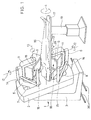
- a gamma camera 1 for the implementation of a method according to the invention comprises, such that shown in Figure 1, a movable base 2 on a frame 3 so as to rotate in rotation about an axis 4 called axis of rotation of the gamma camera 1, said axis 4 being substantially parallel to the ground and passing approximately by the center of gravity of said base 2.
- the frame 3 is movable in lateral translation on along rails 36 orthogonal to axis 4.
- the base 2 carries, in the embodiment of the present description, two arms 5 and 6 arranged with on either side of axis 4, symmetrically. However, in other exemplary embodiments, the base 2 will carry a single arm or even more than two arms.
- Arms 5, 6 can move towards or away radially from axis 4, within window limits 7 and 8 of the base 2, using a device commonly called elevator.
- Each arm 5, 6 is provided, at its free end, of a detector head 9, 10, substantially parallelepiped and rectangle.
- the hanging of the detector head 9, 10 on arm 5, 6 is produced by via a U-shaped stirrup 11.
- the stirrup 11 is movable in rotation relative to the end free of arm 5 which carries it along an axis of rotation 12 orthogonal to axis 4 and called the angulation axis of the detector head 9, 10.
- the detector head 9, 10 is movable in rotation between the edges descendants of stirrup 11 along an axis 13 parallel to axis 4 and called the orientation axis of the head detector 9, 10.
- each arm 5, 6 has a support 14 of a housing 15 comprising a linear source gamma radio transmitter for obtaining projections in transmission.
- a patient's body 16 is placed lying on a bed 17, between active faces 18 of the heads detectors 9 and 10, substantially along axis 4 of rotation of the gamma camera 1.
- the bed 17 is carried by a lifting foot 19 which makes it possible to adjust the height of the patient's body 16 at a desired position.
- Such a bed 17 is described more specifically in the application for French patent published under number 2 684 865 including the content is incorporated herein by reference.
- the gamma camera 1 allows many relative positions of heads detectors 9, 10 relative to the patient's body 16. This richness is a peculiarity of gamma cameras say open stand, in which the heads detectors 9, 10 are not locked in a tunnel.
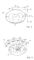
- a detector head 9, 10 essentially comprises, in starting from its active face 18, a collimator 20, a scintillator crystal 21, a network of photo-multiplier tubes 22, and processing circuits 23 connected to an amplification circuit 24.
- the collimator 20 is generally with straight holes. It defines a detection surface 25 of the head detector 9, 10, i.e. a portion of the face active 18 of the detector head 9, 10 capable of ability to detect gamma ⁇ radiation.
- the principle of obtaining an image of the body of a patient 16 is as follows. For a position given in orientation and angulation of a detector head 9, 10, the gamma rays coming from and / or passing through the body of the patient 16, who have a direction of propagation substantially orthogonal to the detection surface 25, pass through the collimator 20 and cause a scintillation 26 in scintillator crystal 21. This scintillation 26 is detected and then amplified by the network of photo-multiplier tubes 22 which develops electrical location signals 27. These signals of location 27 are then processed and we obtain then an image in projection or projection of the body of the patient 16 for the above position.
- FIG. 3 illustrates the principle of the invention.
- the contours of the patient's body 16 are represented, in cross section, by a ellipse 30 with center C.
- this example is not not limiting and the contours of the patient's body 16 can be modeled and represented by a shape any.
- the patient's lungs and heart are respectively referenced 32 and 33.
- the purpose of the review is to collect a information from inside the ellipse 30.
- a detector head 9, 10, the detection area 25 is symbolized by a double arrow, is placed near said body 16.
- a first projection P1 is acquired in a first position P1 of the surface of detection 25 of the detector head 9 or 10 relative to the patient's body 16, then a second projection P2 is acquired in a second position P2 of said surface 25 of this same detector head 9 or 10 by relation to said body 16.
- the two positions P1, P2 are angularly neighboring, that is to say that the angle ⁇ that does the normal 34 to the detection surface 25 in the first position P1 and the normal 35 at said surface 25 in position P2, is weak, less than 10 ° approximately, in practice of the order of 3 °.
- Normal 34, 35 at the detection surfaces 25 intersect in a center C 'which is not necessarily the center C of ellipse 30.
- angle ⁇ can be equal to 0.
- the normals 34, 35 are parallel and it there is no center C '.
- the first projection P1 is truncated. Indeed, the detection surface 25, in practice of the order of 350 x 250 cm, is not sufficient to allow a detection of the entire body of patient 16. From this done, a hatched H1 part, which is not part of the head detection field 9, 10, is not detected. However, the second projection P2 of the body of patient 16 is acquired under such conditions that a portion of the H1 part is detected. A information acquired in the second projection P2 does not so not been in the first P1.
- the second projection P2 is truncated in part H2
- the missing information in the truncated part of a projection is added to from another projection acquired at an angle neighbour.
- the sensor heads 9, 10 are moved from one edge to the other of the patient's body 16.
- the first projection P1 includes image of an edge of the patient's body 16
- the second projection P2 includes the image of the opposite edge said body 16.
- the entire body of patient 16 is then acquired in the two projections P1 and P2 angularly neighboring and the information of a projection being introduced into another and conversely, each projection of the body P1 or P2 of the patient 16 is acquired virtually entirely. It is the reason why we can say that the body of patient 16 is seen in a virtual angular area 180 °. In this sense, the detector heads 9, 10 have a large virtual field of view.
- the method of the invention is advantageously improved by imposing continuity between the information entered in a part truncated from a projection and those acquired in said projection.
- the detector heads 9, 10 are advantageously placed in a so-called 90 ° position, wherein the detection surfaces 25 of said heads 9, 10 are arranged at right angles to one of the other.
- the detection surfaces 25 of said heads 9, 10 are arranged at right angles to one of the other.
- FIG. 1 Such a position is shown in FIG. 1.
- the detector heads 9, 10 are then moved in rotation around patient's body 16, not driven step by step at regular viewing angles through base 2 rotating around its axis 4.
- an initial positioning of the detector heads 9, 10 is carried out relative to the body of the patient 16.
- the heads 9, 10 are placed in respective positions I 9 and I 10 which, on the assumption that the patient's body 16 is centered on the bed 17, make it possible to completely determine the dimensions of the patient's body 16 and bed tray 17 system as well as the center C of said patient.
- the detector head 9 is placed in a horizontal position I 9 and above the patient's body 16 so that the inner edge 37 of the detection surface 25 is vertical to an end point 39 side core 33 of the contour 30 of the patient's body 16, and the sensor head 10 is placed in a 10 vertical I position (90 ° from the head 9) and from the heart 33 of the patient side, so that the inner edge 37 of its detection surface 25 is horizontal to an upper end point 40 of the contour 30 of the patient's body 16.
- the contours of the patient's body 16 disposed on his bed 17 will be completely defined, it that is to say, modeled.
- the interior trajectory is based on the knowledge of the vertical dimensions and horizontal of the patient / bed system whose shape is modeled by an ellipse.
- the dimensions of the ellipse are obtained by manually positioning the camera on the interior path for a particular angle such that a detector is horizontal and above the patient and the other is vertical on the side of the patient.
- the center of aim can be arbitrarily defined as, by example, the center of the ellipse or an organ individual whose location is defined manually. Therefore, for each angle of view, the trajectory is determined by the position of the camera which ensures that the two orthogonal lines passing alternately by the inner edges then the edges outside the detection fields, either tangential to the ellipse.
- the preparatory phase over it is possible to calculate the positions ⁇ (i) for i variant from 0 to n that each of the detector heads 9 will occupy, 10 during the tomographic examination.
- the number n of these positions and the acquisition time is the same that in the case of a tomographic examination taking place without correction of truncations.
- p of n positions are registered: according to a first trajectory T1 of detector heads 9, 10 and n-p other positions register along a second path T2.
- These T1 and T2 trajectories, shown in Figure 5, are advantageously carried out successively.
- One of trajectories, for example the first trajectory T1 begins at ⁇ (0) and ends at ⁇ (8).
- the trajectory T1 is called interior trajectory since it is such that the so-called inner edge of the detection field of the detector head follows the contours of the patient's body 16.
- the trajectory T2 is called external trajectory since it is such that the edge of the detection field opposite the inner edge follows the contours of the body of the patient 16.
- the outer trajectory cannot start a priori in an analytical form.
- Projections acquired in positions ⁇ (0), ⁇ (2), ⁇ (4), ⁇ (6) and ⁇ (8) are angularly close projections acquired in positions ⁇ (1), ⁇ (3), ⁇ (5), ⁇ (7) and ⁇ (9) respectively.
- the reconstructed tomographic image 28 obtained does not will then present no artifacts due to truncation.
- the projection images are shifted to make the projection of the center C of the patient's body identified by its coordinates x C and y C coincide with the center Ci of the projection of coordinates 0 and 0.
- This can be done using a correction method explained in Figure 6B.
- the projection of the center C which appears at the abscissa x C and the ordinate y C of the projection image, is shifted by a quantity -x C and -y C.
Landscapes
- Health & Medical Sciences (AREA)
- Physics & Mathematics (AREA)
- Life Sciences & Earth Sciences (AREA)
- Engineering & Computer Science (AREA)
- General Physics & Mathematics (AREA)
- Molecular Biology (AREA)
- High Energy & Nuclear Physics (AREA)
- Medical Informatics (AREA)
- General Health & Medical Sciences (AREA)
- Optics & Photonics (AREA)
- Nuclear Medicine, Radiotherapy & Molecular Imaging (AREA)
- Spectroscopy & Molecular Physics (AREA)
- Biomedical Technology (AREA)
- Biophysics (AREA)
- Public Health (AREA)
- Pathology (AREA)
- Radiology & Medical Imaging (AREA)
- Heart & Thoracic Surgery (AREA)
- Surgery (AREA)
- Animal Behavior & Ethology (AREA)
- Theoretical Computer Science (AREA)
- Veterinary Medicine (AREA)
- Nuclear Medicine (AREA)
- Magnetic Resonance Imaging Apparatus (AREA)
- Apparatus For Radiation Diagnosis (AREA)
- Steroid Compounds (AREA)
- Image Processing (AREA)
- Image Analysis (AREA)
Description
- la figure 1 montre, en perspective, une gamma caméra pour la mise en oeuvre d'une méthode selon l'invention ;
- la figure 2 illustre, en coupe et de manière schématique, une tête détectrice d'une gamma caméra pour la mise en oeuvre d'une méthode selon l'invention ;
- la figure 3 schématise le principe d'une méthode selon l'invention ;
- la figure 4 représente le positionnement initial des têtes détectrices pour l'application d'une méthode selon l'invention ;
- la figure 5 représente les trajectoires empruntées par les têtes détectrices lors d'un examen tomographique conforme à une méthode selon l'invention ;
- la figure 6A schématise la projection d'un centre C lors d'une acquisition selon l'invention ; et
- la figure 6B schématise un centrage des images en projection acquises dans une méthode selon l'invention.
Claims (14)
- Méthode d'obtention, en médecine nucléaire, d'une image du corps d'un patient (16), selon laquellecaractérisée en ce que, pour un segment donné appartenant à une partie tronquée de ladite première image en projection (P1), on remplace ce dernier par un segment, obtenu de ladite seconde image en projection (P2), n'ayant pas la même orientation que ledit segment donné, la différence d'orientation correspondant à la différence de la position angulaire (α) de la tête détectrice (9 ou 10) entre l'acquisition de ladite première image et ladite seconde image, les positions angulaires respectives étant voisines dans la mesure où le segment donné et le segment obtenu de ladite seconde image en projection se confondent ou du moins tendent vers un segment identique, de manière à permettre de corriger les troncatures.on place le corps du patient (16) sur un lit (17) d'une machine de médecine nucléaire (1) comportant au moins une tête détectrice (9 ou 10) munie d'une surface de détection (26) de rayonnements nucléaires (γ) ;on acquiert, avec une tête détectrice (9 ou 10), une première image en projection (P1) tronquée du corps du patient (16);on acquiert, avec ladite tête détectrice (9 ou 10), une seconde image en projection (P2) du corps du patient (16) et,on introduit une information de ladite seconde image (P2) dans ladite première image (P1) en vue de la corriger dans sa partie tronquée (H1);
- Méthode selon la revendication 1, caractérisée en ce que la seconde image en projection (P2) acquise est tronquée (H2), et en ce que on introduit une information de la première image en projection (P1) dans ladite seconde image (P2) en vue de la corriger dans sa partie tronquée (H2).
- Méthode selon l'une des revendications 1 ou 2, caractérisée en ce que ladite différence de la position angulaire (α) de la tête détectrice (9 ou 10) entre l'acquisition de ladite première image et ladite seconde image est inférieure à 10° environ.
- Méthode selon l'une des revendications 1, 2 ou 3, caractérisée en ce que la première image en projection (P1) acquise comprend l'image d'un bord du corps du patient (16), et en ce que la seconde image en projection (P2) acquise comprend l'image du bord opposé du corps du patient (16).
- Méthode selon l'une des revendications 1, à 4, caractérisée en ce que la totalité du corps du patient (16) est acquise au moyen des deux projections (P1,P2) angulairement voisines de manière à permettre d'obtenir une continuité dans les informations introduites dans une partie tronquée d'une projection et celles acquises dans ladite projection.
- Méthode selon l'une des revendications précédentes, caractérisée en ce que les images en projection sont acquises en tomographie.
- Méthode selon la revendication 6, caractérisée en ce que la tomographie est une tomographie cardiaque avec correction d'atténuation, les têtes détectrices (9, 10) étant disposées dans une position dite à 90°.
- Méthode selon l'une des revendications 6 ou 7, caractérisée en ce que, préalablement à l'examen tomographique, on dispose chaque tête détectrice (9, 10) dans une position (I9, I10) permettant de déterminer les dimensions du corps du patient ainsi que son centre C.
- Méthode selon la revendication 8, caractérisée en ce que l'on impose que le coeur (33) ne doit jamais être tronqué.
- Méthode selon l'une des revendications précédentes, caractérisée en ce que l'image reconstruite (28) est une image tomographique obtenue par l'acquisition d'images en projection du corps du patient prises sous différentes angles α(i).
- Méthode selon l'une des revendications 6 à 10, caractérisée en ce que p des n images en projection sont acquises selon une première trajectoire (T1) de la (des) tête(s) détectrice(s) (9, 10) et n-p autres images sont acquises selon une seconde trajectoire (T2) de ladite (lesdites) tête(s) (9, 10).
- Méthode selon la revendication 11, caractérisée en ce que l'une des trajectoires, par exemple la première trajectoire (T1), dite trajectoire intérieure, est telle qu'un bord dit intérieur du champ de détection de la tête détectrice suit les bords du corps du patient (16).
- Méthode selon l'une des revendications 11 ou 12, caractérisée en ce que la seconde trajectoire (T2), dite trajectoire extérieure, est telle qu'un bord du champ de détection, opposé au bord dit intérieur, suit les bords du corps du patient (16).
- Méthode selon l'une des revendications précédentes, caractérisée en ce que les images en projection acquises le sont en émission ou en transmission.
Applications Claiming Priority (2)
| Application Number | Priority Date | Filing Date | Title |
|---|---|---|---|
| FR9507834A FR2736163B1 (fr) | 1995-06-29 | 1995-06-29 | Methode d'obtention, en medecine nucleaire, d'une image du corps d'un patient corrigee des troncatures |
| FR9507834 | 1995-06-29 |
Publications (3)
| Publication Number | Publication Date |
|---|---|
| EP0764855A2 EP0764855A2 (fr) | 1997-03-26 |
| EP0764855A3 EP0764855A3 (fr) | 1998-07-01 |
| EP0764855B1 true EP0764855B1 (fr) | 2001-09-05 |
Family
ID=9480512
Family Applications (1)
| Application Number | Title | Priority Date | Filing Date |
|---|---|---|---|
| EP96401428A Expired - Lifetime EP0764855B1 (fr) | 1995-06-29 | 1996-06-27 | Méthode d'obtention, en médecine nucléaire, d'une image du corps d'un patient corrigée des troncatures |
Country Status (8)
| Country | Link |
|---|---|
| US (1) | US5752916A (fr) |
| EP (1) | EP0764855B1 (fr) |
| JP (1) | JPH09171078A (fr) |
| AT (1) | ATE205304T1 (fr) |
| CA (1) | CA2180317A1 (fr) |
| DE (1) | DE69614955T2 (fr) |
| FR (1) | FR2736163B1 (fr) |
| IL (1) | IL118758A (fr) |
Families Citing this family (8)
| Publication number | Priority date | Publication date | Assignee | Title |
|---|---|---|---|---|
| JP3878259B2 (ja) * | 1996-11-13 | 2007-02-07 | 東芝医用システムエンジニアリング株式会社 | 医用画像処理装置 |
| FR2773887B1 (fr) | 1998-01-16 | 2000-03-17 | Smv Int | Articulation orientable pour dispositif de correction d'attenuation de transmission |
| JP4170449B2 (ja) * | 1998-07-07 | 2008-10-22 | 株式会社東芝 | トランスミッションctのトランケーション補正装置、核医学診断装置及びトランケーション補正方法 |
| US7242002B2 (en) * | 2004-03-16 | 2007-07-10 | General Electric Medical Systems Israel Ltd. | Compact gamma camera |
| US7381961B2 (en) * | 2004-09-24 | 2008-06-03 | Digirad Corporation | Multi-small field-of-view detector head SPECT system that scans over 360Å |
| EP1828808B1 (fr) * | 2004-12-17 | 2010-04-21 | Koninklijke Philips Electronics N.V. | Algorithme de compensation de troncature pour reconstruction iterative |
| US20070076933A1 (en) * | 2005-09-30 | 2007-04-05 | Jared Starman | Estimating the 0th and 1st moments in C-arm CT data for extrapolating truncated projections |
| US7737406B2 (en) * | 2006-09-27 | 2010-06-15 | Siemens Medical Solutions Usa, Inc. | Compensating for truncated CT images for use as attenuation maps in emission tomography |
Family Cites Families (10)
| Publication number | Priority date | Publication date | Assignee | Title |
|---|---|---|---|---|
| US3970853A (en) * | 1975-06-10 | 1976-07-20 | The United States Of America As Represented By The United States Energy Research And Development Administration | Transverse section radionuclide scanning system |
| JPS5753673A (en) * | 1980-09-17 | 1982-03-30 | Toshiba Corp | Emission ct |
| US4618772A (en) * | 1982-05-24 | 1986-10-21 | Siemens Gammasonics, Inc. | Nuclear imaging apparatus |
| JPH0652301B2 (ja) * | 1985-04-11 | 1994-07-06 | 株式会社東芝 | エミツシヨンct装置 |
| US4782233A (en) * | 1986-06-20 | 1988-11-01 | Digital Scintigraphics, Inc. | Multifield collimator system and method and radionuclide emission tomography camera using same |
| FR2675927B1 (fr) * | 1991-04-25 | 1993-07-30 | Inst Nat Rech Inf Automat | Procede et dispositif d'aide a l'inspection d'un corps, notamment pour la tomographie. |
| FR2715554B1 (fr) * | 1994-02-02 | 1996-03-29 | Sopha Medical | Gamma caméra à bras tournant. |
| US5457724A (en) * | 1994-06-02 | 1995-10-10 | General Electric Company | Automatic field of view and patient centering determination from prescan scout data |
| US5565684A (en) * | 1995-06-30 | 1996-10-15 | The University Of Utah | Three-dimensional SPECT reconstruction of combined cone-beam and fan-beam data |
| US5672877A (en) * | 1996-03-27 | 1997-09-30 | Adac Laboratories | Coregistration of multi-modality data in a medical imaging system |
-
1995
- 1995-06-29 FR FR9507834A patent/FR2736163B1/fr not_active Expired - Fee Related
-
1996
- 1996-06-27 DE DE69614955T patent/DE69614955T2/de not_active Expired - Lifetime
- 1996-06-27 AT AT96401428T patent/ATE205304T1/de not_active IP Right Cessation
- 1996-06-27 EP EP96401428A patent/EP0764855B1/fr not_active Expired - Lifetime
- 1996-06-27 US US08/673,792 patent/US5752916A/en not_active Expired - Fee Related
- 1996-06-30 IL IL11875896A patent/IL118758A/xx not_active IP Right Cessation
- 1996-07-01 JP JP8190037A patent/JPH09171078A/ja not_active Withdrawn
- 1996-07-02 CA CA002180317A patent/CA2180317A1/fr not_active Abandoned
Also Published As
| Publication number | Publication date |
|---|---|
| DE69614955D1 (de) | 2001-10-11 |
| US5752916A (en) | 1998-05-19 |
| EP0764855A2 (fr) | 1997-03-26 |
| IL118758A (en) | 2001-03-19 |
| DE69614955T2 (de) | 2002-04-11 |
| IL118758A0 (en) | 1996-10-16 |
| ATE205304T1 (de) | 2001-09-15 |
| JPH09171078A (ja) | 1997-06-30 |
| FR2736163A1 (fr) | 1997-01-03 |
| CA2180317A1 (fr) | 1996-12-30 |
| EP0764855A3 (fr) | 1998-07-01 |
| FR2736163B1 (fr) | 1997-08-22 |
Similar Documents
| Publication | Publication Date | Title |
|---|---|---|
| JP5268499B2 (ja) | 計算機式断層写真法(ct)イメージング・システム | |
| EP0517600B1 (fr) | Procédé d'acquisition tomographique, à deux détecteurs, à centre de visée distinct du centre de rotation | |
| CN104136938B (zh) | 谱成像 | |
| JP2000333939A (ja) | X線診断装置 | |
| US7039151B2 (en) | Radiographic image processing method and radiation imaging device | |
| FR2914175A1 (fr) | Chaine d'acquisition et de traitement d'image pour radiographie a double energie utilisant un detecteur a panneau plat portable | |
| US8926177B2 (en) | Source side monitoring device for an imaging system | |
| WO2016012435A1 (fr) | Systeme d'imagerie par rayons x permettant la correction du diffuse et la detection precise de la distance source detecteur | |
| EP0764855B1 (fr) | Méthode d'obtention, en médecine nucléaire, d'une image du corps d'un patient corrigée des troncatures | |
| JP4408664B2 (ja) | コーンビームx線ct装置及びそれに用いるファントム | |
| JPH10509069A (ja) | 断層撮影イメージ・データの正規化 | |
| EP0341143A1 (fr) | Dispositif et procédé de tomographie à grande cadence d'acquisition | |
| EP3368919B1 (fr) | Collimateur tournant pour determiner la position d'un element muni de capteurs dans un systeme d'imagerie par rayons x | |
| EP0517602B1 (fr) | Gamma caméra à deux détecteurs en opposition ayant des mouvements radiaux indépendants | |
| JP2001330568A5 (fr) | ||
| EP4010739A1 (fr) | Collimateur tournant pour un système de détection de rayons x | |
| JPH0763464B2 (ja) | X線ct装置 | |
| FR2749699A1 (fr) | Collimateur a champ de vue multiple et systeme d'imagerie medicale comportant un tel collimateur | |
| FR2697918A1 (fr) | Dispositif de scintigraphie. | |
| JP4603086B2 (ja) | プロジェクションデータ補正方法、プロジェクションデータ補正装置、記録媒体および放射線断層撮像装置 | |
| JP2001311775A (ja) | 透過放射線補正型ガンマ線カメラ及びそれを用いた診断画像形成方法 | |
| JP4451554B2 (ja) | プロジェクションデータ補正方法、プロジェクションデータ補正装置、記録媒体および放射線断層撮像装置 | |
| FR2752947A1 (fr) | Machine de medecine nucleaire | |
| FR2700039A1 (fr) | Procédé pour maintenir un niveau faible d'artefacts dans l'image fournie par un appareil de tomographie. | |
| EP2449533B1 (fr) | Procede et dispositif d'imagerie a rayons x a traitement tridimensionnel |
Legal Events
| Date | Code | Title | Description |
|---|---|---|---|
| PUAI | Public reference made under article 153(3) epc to a published international application that has entered the european phase |
Free format text: ORIGINAL CODE: 0009012 |
|
| AK | Designated contracting states |
Kind code of ref document: A2 Designated state(s): AT BE DE ES GB IT NL |
|
| PUAL | Search report despatched |
Free format text: ORIGINAL CODE: 0009013 |
|
| AK | Designated contracting states |
Kind code of ref document: A3 Designated state(s): AT BE DE ES GB IT NL |
|
| 17P | Request for examination filed |
Effective date: 19981231 |
|
| 17Q | First examination report despatched |
Effective date: 19990831 |
|
| GRAG | Despatch of communication of intention to grant |
Free format text: ORIGINAL CODE: EPIDOS AGRA |
|
| GRAG | Despatch of communication of intention to grant |
Free format text: ORIGINAL CODE: EPIDOS AGRA |
|
| GRAH | Despatch of communication of intention to grant a patent |
Free format text: ORIGINAL CODE: EPIDOS IGRA |
|
| GRAH | Despatch of communication of intention to grant a patent |
Free format text: ORIGINAL CODE: EPIDOS IGRA |
|
| GRAA | (expected) grant |
Free format text: ORIGINAL CODE: 0009210 |
|
| AK | Designated contracting states |
Kind code of ref document: B1 Designated state(s): AT BE DE ES GB IT NL |
|
| PG25 | Lapsed in a contracting state [announced via postgrant information from national office to epo] |
Ref country code: NL Free format text: LAPSE BECAUSE OF FAILURE TO SUBMIT A TRANSLATION OF THE DESCRIPTION OR TO PAY THE FEE WITHIN THE PRESCRIBED TIME-LIMIT Effective date: 20010905 Ref country code: IT Free format text: LAPSE BECAUSE OF FAILURE TO SUBMIT A TRANSLATION OF THE DESCRIPTION OR TO PAY THE FEE WITHIN THE PRE;WARNING: LAPSES OF ITALIAN PATENTS WITH EFFECTIVE DATE BEFORE 2007 MAY HAVE OCCURRED AT ANY TIME BEFORE 2007. THE CORRECT EFFECTIVE DATE MAY BE DIFFERENT FROM THE ONE RECORDED.SCRIBED TIME-LIMIT Effective date: 20010905 Ref country code: GB Free format text: LAPSE BECAUSE OF FAILURE TO SUBMIT A TRANSLATION OF THE DESCRIPTION OR TO PAY THE FEE WITHIN THE PRESCRIBED TIME-LIMIT Effective date: 20010905 |
|
| REF | Corresponds to: |
Ref document number: 205304 Country of ref document: AT Date of ref document: 20010915 Kind code of ref document: T |
|
| PG25 | Lapsed in a contracting state [announced via postgrant information from national office to epo] |
Ref country code: AT Free format text: LAPSE BECAUSE OF FAILURE TO SUBMIT A TRANSLATION OF THE DESCRIPTION OR TO PAY THE FEE WITHIN THE PRESCRIBED TIME-LIMIT Effective date: 20010919 |
|
| REF | Corresponds to: |
Ref document number: 69614955 Country of ref document: DE Date of ref document: 20011011 |
|
| NLV1 | Nl: lapsed or annulled due to failure to fulfill the requirements of art. 29p and 29m of the patents act | ||
| PG25 | Lapsed in a contracting state [announced via postgrant information from national office to epo] |
Ref country code: DE Free format text: LAPSE BECAUSE OF THE APPLICANT RENOUNCES Effective date: 20020208 |
|
| GBV | Gb: ep patent (uk) treated as always having been void in accordance with gb section 77(7)/1977 [no translation filed] |
Effective date: 20010905 |
|
| PG25 | Lapsed in a contracting state [announced via postgrant information from national office to epo] |
Ref country code: ES Free format text: LAPSE BECAUSE OF FAILURE TO SUBMIT A TRANSLATION OF THE DESCRIPTION OR TO PAY THE FEE WITHIN THE PRESCRIBED TIME-LIMIT Effective date: 20020326 |
|
| PG25 | Lapsed in a contracting state [announced via postgrant information from national office to epo] |
Ref country code: BE Free format text: LAPSE BECAUSE OF NON-PAYMENT OF DUE FEES Effective date: 20020630 |
|
| PLBE | No opposition filed within time limit |
Free format text: ORIGINAL CODE: 0009261 |
|
| STAA | Information on the status of an ep patent application or granted ep patent |
Free format text: STATUS: NO OPPOSITION FILED WITHIN TIME LIMIT |
|
| 26N | No opposition filed | ||
| BERE | Be: lapsed |
Owner name: *SMV INTERNATIONAL Effective date: 20020630 |