EP0764859B1 - Dispositif atténuateur à fibre optique - Google Patents
Dispositif atténuateur à fibre optique Download PDFInfo
- Publication number
- EP0764859B1 EP0764859B1 EP96107727A EP96107727A EP0764859B1 EP 0764859 B1 EP0764859 B1 EP 0764859B1 EP 96107727 A EP96107727 A EP 96107727A EP 96107727 A EP96107727 A EP 96107727A EP 0764859 B1 EP0764859 B1 EP 0764859B1
- Authority
- EP
- European Patent Office
- Prior art keywords
- fiber
- optical
- ferrule
- attenuation
- length
- Prior art date
- Legal status (The legal status is an assumption and is not a legal conclusion. Google has not performed a legal analysis and makes no representation as to the accuracy of the status listed.)
- Expired - Lifetime
Links
- 239000013307 optical fiber Substances 0.000 title claims description 72
- 230000003287 optical effect Effects 0.000 claims description 126
- 239000000835 fiber Substances 0.000 claims description 84
- 238000000034 method Methods 0.000 claims description 4
- 230000002035 prolonged effect Effects 0.000 claims 3
- 230000004927 fusion Effects 0.000 claims 1
- 238000004519 manufacturing process Methods 0.000 description 6
- 238000007526 fusion splicing Methods 0.000 description 4
- 238000003466 welding Methods 0.000 description 4
- 239000012535 impurity Substances 0.000 description 3
- 230000004323 axial length Effects 0.000 description 2
- 238000010586 diagram Methods 0.000 description 2
- 230000001105 regulatory effect Effects 0.000 description 2
- XUIMIQQOPSSXEZ-UHFFFAOYSA-N Silicon Chemical compound [Si] XUIMIQQOPSSXEZ-UHFFFAOYSA-N 0.000 description 1
- 230000000712 assembly Effects 0.000 description 1
- 238000000429 assembly Methods 0.000 description 1
- 230000008859 change Effects 0.000 description 1
- 239000011248 coating agent Substances 0.000 description 1
- 238000000576 coating method Methods 0.000 description 1
- 230000001276 controlling effect Effects 0.000 description 1
- 230000008878 coupling Effects 0.000 description 1
- 238000010168 coupling process Methods 0.000 description 1
- 238000005859 coupling reaction Methods 0.000 description 1
- 230000002950 deficient Effects 0.000 description 1
- 238000005516 engineering process Methods 0.000 description 1
- 230000001747 exhibiting effect Effects 0.000 description 1
- 239000011521 glass Substances 0.000 description 1
- 230000037361 pathway Effects 0.000 description 1
- 238000005498 polishing Methods 0.000 description 1
- 229910052710 silicon Inorganic materials 0.000 description 1
- 239000010703 silicon Substances 0.000 description 1
Images


Classifications
-
- G—PHYSICS
- G02—OPTICS
- G02B—OPTICAL ELEMENTS, SYSTEMS OR APPARATUS
- G02B6/00—Light guides; Structural details of arrangements comprising light guides and other optical elements, e.g. couplings
- G02B6/24—Coupling light guides
- G02B6/26—Optical coupling means
- G02B6/264—Optical coupling means with optical elements between opposed fibre ends which perform a function other than beam splitting
- G02B6/266—Optical coupling means with optical elements between opposed fibre ends which perform a function other than beam splitting the optical element being an attenuator
-
- G—PHYSICS
- G02—OPTICS
- G02B—OPTICAL ELEMENTS, SYSTEMS OR APPARATUS
- G02B6/00—Light guides; Structural details of arrangements comprising light guides and other optical elements, e.g. couplings
- G02B6/02—Optical fibres with cladding with or without a coating
-
- G—PHYSICS
- G02—OPTICS
- G02B—OPTICAL ELEMENTS, SYSTEMS OR APPARATUS
- G02B6/00—Light guides; Structural details of arrangements comprising light guides and other optical elements, e.g. couplings
- G02B6/24—Coupling light guides
- G02B6/36—Mechanical coupling means
- G02B6/38—Mechanical coupling means having fibre to fibre mating means
- G02B6/3807—Dismountable connectors, i.e. comprising plugs
- G02B6/381—Dismountable connectors, i.e. comprising plugs of the ferrule type, e.g. fibre ends embedded in ferrules, connecting a pair of fibres
- G02B6/3818—Dismountable connectors, i.e. comprising plugs of the ferrule type, e.g. fibre ends embedded in ferrules, connecting a pair of fibres of a low-reflection-loss type
- G02B6/3822—Dismountable connectors, i.e. comprising plugs of the ferrule type, e.g. fibre ends embedded in ferrules, connecting a pair of fibres of a low-reflection-loss type with beveled fibre ends
-
- G—PHYSICS
- G02—OPTICS
- G02B—OPTICAL ELEMENTS, SYSTEMS OR APPARATUS
- G02B6/00—Light guides; Structural details of arrangements comprising light guides and other optical elements, e.g. couplings
- G02B6/24—Coupling light guides
- G02B6/36—Mechanical coupling means
- G02B6/38—Mechanical coupling means having fibre to fibre mating means
- G02B6/3807—Dismountable connectors, i.e. comprising plugs
- G02B6/3833—Details of mounting fibres in ferrules; Assembly methods; Manufacture
- G02B6/3846—Details of mounting fibres in ferrules; Assembly methods; Manufacture with fibre stubs
Definitions
- the present invention generally relates to a new optical fiber attenuator produced by using an optical fiber (hereunder referred to as an optical attenuation fiber), which is intentionally doped with impurities and thus posseses definite optical attenuation characteristics. More particularly, the present invention relates to an optical fiber attenuator which can accurately impart a fixed optical attenuation coefficient to an optical attenuation fiber used therein even if it is difficult to manufacture the optical attenuation fiber by precisely controlling the optical attenuation per predetermined length thereof (namely, the attenuation coefficient thereof).
- a fixed value fiber optic attenuator is known from the US 5,109,468.
- the attenuation is achieved by providing an optical fiber pathway, that has a bend or a radial offset between two ends of the fiber.
- an optical fiber attenuator comprising an attenuation fiber that is coiled inside a housing.
- the attenuation fiber is cut to a predetermined length.
- this arrangement needs a rather large height of the housing.
- the inventor of the present invention has made an attempt to produce an optical attenuator of the connector type or an optical attenuator connectable with a connector by utilizing an optical fiber which is doped with impurities and thus has a considerably large optical attenuation coefficient or optical attenuation per unit fiber length.
- Fig. 8 is a sectional view of a conventional optical attenuator of the connector type.
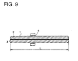
- Fig. 9 is a sectional view of a ferrule assembly portion taken out of the optical attenuator.
- a through hole 2 is bored in the central portion of a cylindrical ferrule 1 of the ferrule assembly portion of Fig. 9 for use in the optical attenuator.
- the optical attenuation fiber 3 is inserted into this through hole 2 and is glued to the inner surface thereof.
- a flange 4 is fixed onto the circumferential surface of the ferrule 1. This flange 4 serves to limit the positions in the direction of the axis of and in the circumferential direction of the ferrule assembly portion.
- a plug housing 5 (Fig. 8) consists of body components 5A and 5B. Further, an alignment sleeve 7 is provided in the component 5A. An end part of the cylindrical ferrule 1 of the ferrule assembly portion is inserted into the alignment sleeve 7 and is connected to the component 5B in such a way that the component 5B inhibits the rotation of the flange 4.
- a coupling nut 6 is rotatably mounted on the plug housing 5.
- An optical fiber plug having an attenuator at an edge portion thereof is formed by connecting a ferrule of another optical fiber connector (not shown) with the other end part of the alignment sleeve 7.
- the formed optical attenuator has total attenuation of LxA dB.
- optical attenuation of 3, 5, 10, 15 or 20 dB is normally required of an optical attenuator.
- arbitrary intermediate attenuation values such as 8 ⁇ 0.8 dB and 13 ⁇ 1.3 dB are sometimes required of the attenuator when utilized for some use.
- optical attenuation is 20 ⁇ 2 dB in the case that the axial length L of the ferrule 1 is equal to 20 mm
- the optical fiber should be produced in such a way that the optical attenuation per unit length of the optical fiber is A with an error of not over ⁇ 10 %.
- the optical attenuation per unit length of the optical fiber becomes A with an error of ⁇ 20 % or so.
- L 20 mm
- the optical attenuation per unit length of the optical fiber becomes large, namely, 20 ⁇ 4 dB. Consequently, the value of the optical attenuation per unit length of the optical fiber cannot be within the specification.
- optical fibers whose optical attenuation per unit length is A with an error of not over ⁇ 10 %, are selected, the fraction defective of the optical fibers becomes inevitably large. Because of the difficulty in regulating the lengths of ferrules 1 individually, there is the necessity of checking the produced optical attenuation fibers and selecting and using only acceptable optical attenuation fibers. Thus, inevitably, the manufacturing cost becomes high.
- Optical attenuation fibers are adapted to absorb light, as a result of doping silicon glass of ordinary optical fibers with impurities such as Co and Cr.
- the management of the manufacturing process thereof is not easy.
- an object of the present invention is to realize the mass production of optical attenuators which can provide arbitrary desired attenuation, by using optical attenuation fibers.
- Another object of the present invention is to provide optical attenuators of various forms, which can be used for various uses.
- the optical attenuation fiber is cut or shortened by being polished in such a manner as to be able to obtain predetermined attenuation when connected to the ordinary optical fiber before or after fixed to the ferrule.
- a connection between the optical attenuation fiber and the ordinary optical fiber may be made by performing a fusion splicing through the use of a discharge arc.
- the ordinary optical fiber is cut to a fixed length. Moreover, a cut edge portion of the ordinary optical fiber is fixed to another ferrule and is polished. Furthermore, the latter ferrule is coupled to the former ferrule for accepting and fixing the latter end portion of the optical attenuation fiber through an alignment sleeve.
- an angular positioning flange may be provided in such a manner as to be integral with the alignment sleeve.
- end-faces of the optical attenuation fiber and the former ferrule and end-faces of the ordinary optical fiber and the latter ferrule are polished slantwise with respect to a plane perpendicular to the optical axis thereof. Thereby, the reflection loss thereof can be reduced.
- each of the ferrules may be a face inclined at an angle of 8 degrees or more to the plane perpendicular to the optical axis thereof and further may be polished into a spherical surface. Thereby, the reflection loss thereof can be further reduced.
- the ferrules are optical fiber connector ferrules.
- the connecting position, at which the ferrule is connected to the ordinary optical fiber, is established in the ferrule.
- a coating or covering portion of the ordinary optical fiber is fixed to a pipe with a flange, which is secured to the ferrule.
- the optical attenuator is formed in such a manner as to be of the type in which the optical attenuator is built into the optical fiber connector ferrule.
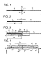
- FIG. 4 is a sectional view of an optical attenuator according to a first embodiment of the present invention.
- FIG. 1 is a sectional diagram for illustrating a welding step for forming an optical attenuation fiber assembly (FA) constitutive of said first embodiment of optical attenuator.
- FA optical attenuation fiber assembly
- an end-face 11 of an optical attenuation fiber 9 of indefinite length (whose attenuation per unit length may differ from a nominal value) is butted against an end-face 12 of an ordinary optical fiber 10 of also indefinite length.
- a fusion splicing is performed on the surfaces 11 and 12 by using a discharge arc 13.
- the optical attenuation fiber 9 is cut to a length L 2 , by which the desired optical attenuation is obtained.
- the ordinary optical fiber 10 is also cut to an appropriate length such that the total length of the optical attenuation fiber assembly (F) thus formed is substantially equal to the overall length of the two ferrules 16 and 20 assembled together as described thereafter.
- a minute through hole 14, which is used to precisely accept an end portion of the optical attenuation fiber 9 of the assembly F, and a stepped or counterbored hole 15 are bored in the central portion of a first cylindrical ferrule 16.
- another through hole 18, into which the outside cylindrical surface 17 of a ferrule 16 is inserted, is bored in a cylindrical alignment sleeve 19.
- a nearly half-length part of the first ferrule 16 is inserted into and glued to the cylindrical alignment sleeve 19.
- the optical attenuation fiber 9 of the optical attenuation fiber assembly (F) is inserted into and glued to the central minute through hole 14 of the first ferrule 16.
- each of the optical attenuation fiber 9 and the ordinary optical fiber 10 cannot be inserted into the central minute through hole of the other of these ferrules owing to the fact that the optical axes of the optical attenuation fiber and the ordinary optical fiber cannot be aligned (namely, the misalignment between the optical axes thereof) at the fusion splicing connection portion therebetween, and to the deformation of these optical fibers.
- the ordinary optical fiber 10 of the assembly F is inserted into and fixed to a second ferrule 20 which is of nearly shape with the first ferrule 16. As shown in FIG. 4, the ordinary optical fiber 10 is inserted into and glued to the central minute through hole 21 of the second ferrule 20. Simultaneously, the outside cylindrical surface 22 of the ferrule 20 is inserted into and glued to the alignment sleeve hole 18. Thereafter, a polishing finish is put on each of ferrule end surfaces 23 and 24. Thereby, the optical attenuator (FA) is obtained.
- FA optical attenuator
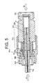
- FIG. 5 is a sectional view of an example of an optical attenuator of the present invention, in which the aforementioned optical attenuator (FA) is mounted into the plug housing (PH) of a single-core optical fiber connector comprising the two body components 5A and 5B.
- the ferrule 20 provided at the side of the ordinary optical fiber 10 of the optical attenuation fiber assembly (F) is inserted into and coupled to an alignment sleeve 7 provided in the part 5A of the plug housing PH.
- the flange 19a of the alignment sleeve 19 of the optical attenuator (FA) is sandwiched and held between the body components 5A and 5B in such a manner as to be in a state in which the rotation of the flange 19a is restrained.
- the attenuator can be inserted into an optical fiber line by inserting optical fibers into the attenuator from the directions of arrows A and B, respectively, and connecting optical fibers with each other.
- FIG. 6 is a sectional view of another embodiment of optical attenuator of the present invention.
- an optical attenuation fiber assembly (F) consists of an optical attenuation fiber 9 and an ordinary optical fiber 10.
- the method of manufacturing or assembling this optical attenuation fiber assembly is the same as described by referring to FIGs. 1 and 2.
- a first ferrule 116 has thin tip end portions. Further, a hole for accepting and supporting the optical attenuation fiber 9 and a stepped hole 118 communicating with such a hole are bored in the ferrule 116. Moreover, an end portion of the optical attenuation fiber 9 is accepted by and glued and fixed to the hole for accepting and supporting the optical attenuation fiber 9.
- a second ferrule 120 has thin tip end portions. Further, a hole for accepting and supporting the ordinary optical fiber 10 and a stepped hole 123 communicating with such a hole are bored in the ferrule 120. Moreover, an end portion of the ordinary optical fiber 10 is accepted by and glued and fixed to the hole for accepting and supporting the ordinary optical fiber. Each of the ferrules 116 and 120 is inserted into and fixed to a sleeve 119 with a flange 119a.
- An end portion 125 of the ferrule 116 and an end portion 126 of the ferrule 120 are formed as surfaces inclined at angles of 8 degrees or more to planes which are perpendicular to the optical axis of the assembly and are polished into spherical surface.
- FIG. 7 is a sectional view of still another embodiment of the present invention, in which an optical attenuation fiber assembly (F) is mounted into an optical connector ferrule.
- An optical attenuation fiber 33 is connected to an ordinary optical fiber portion 34, from which a covering portion 31 is eliminated, by performing a discharge arc welding.
- the optical attenuation fiber 33 is cut at an end thereof in such a manner as to become slightly longer than the length designated by L 2 in this figure.
- a covering portion 31 of the optical fiber is inserted into a hole 32 of a pipe 30 with a flange 30A and is fixed thereto.
- the connecting point, at which the optical attenuation fiber 33 and the ordinary optical fiber 34 are welded, is located in a stepped hole.
- a stepped hole is counterbored in a flange-side portion of the hole 32 of the pipe 30.
- the base portion of a ferrule 27 is inserted into this counterbored hole and is fixed thereto. Both end portions of the optical attenuation fiber 33 and the ferrule 17 surrounding this fiber are polished simultaneously.
- This assembly is used as an optical connector having an optical attenuation function.
- optical attenuation fibers each of which exhibits a predetermined value of optical attenuation per unit length thereof.
- an optical attenuation fiber assembly exhibiting accurate optical attenuation can be produced by employing an optical attenuator which uses an optical attenuation fiber of the present invention.
- optical attenuation fiber assemblies which exhibit arbitrary optical attenuation, can be easily produced. Furthermore, only the regulation of the length of an optical attenuation fiber is necessary for regulating the optical attenuation caused by the optical attenuation fiber assembly. For such a purpose, it is not necessary at all to regulate other components, for example, to change the length of a ferrule.
- optical attenuator of the present invention can be incorporated into optical devices, each of which is required to have an optical attenuation function, other than the aforementioned embodiments.
Landscapes
- Physics & Mathematics (AREA)
- General Physics & Mathematics (AREA)
- Optics & Photonics (AREA)
- Light Guides In General And Applications Therefor (AREA)
- Optical Couplings Of Light Guides (AREA)
- Mechanical Coupling Of Light Guides (AREA)
Claims (10)
- Procédé d'assemblage d'un atténuateur à fibre optique (FA) comprenant une ferrule (16, 20 ; 116, 120 ; 27) de longueur prédéterminée, dans lequel une première extrémité d'une fibre d'atténuation optique (9 ; 33) est raccordée à une première extrémité d'une portion non revêtue (10 ; 34) d'une fibre optique ordinaire,
la fibre d'atténuation optique (9 ; 33) est coupée ou raccourcie par polissage jusqu'à une longueur efficace (L2) avant ou après avoir été assujettie à la ferrule (16, 20 ; 116, 120 ; 27) de façon à obtenir une atténuation souhaitée,
la longueur de la portion non revêtue (10 ; 34) de la fibre optique ordinaire est choisie en fonction de la longueur (L2) choisie pour la section finie de la fibre d'atténuation (9 ; 33) de façon à ce que la longueur globale de la section finie de la fibre d'atténuation optique et de la portion finie non revêtue (10 ; 34) de la fibre optique ordinaire soit égale à la longueur prédéterminée de la ferrule (16, 20 ; 116, 120 ; 27), et dans lequel
la deuxième extrémité de la section finie de la fibre d'atténuation optique (9 ; 33) est insérée et fixée dans une extrémité correspondante (14 ; 22) de la ferrule (16, 20 ; 116, 120 ; 27) de façon à ce que ladite section finie de la fibre d'atténuation optique (9 ; 33) prolongée par ladite portion d'extrémité finie non revêtue (10 ; 34) de la fibre ordinaire se prolonge depuis ladite extrémité jusqu' à l'autre extrémité de la ferrule (16, 20 ; 116, 120 ; 27). - Procédé selon la revendication 1, la ferrule comprenant une première partie (16 ; 116) et une deuxième partie (20 ; 120) de longueur prédéterminée, dans lequel
la portion non revêtue (10) de la fibre optique ordinaire est coupée à une longueur finie,
la deuxième extrémité de ladite portion non revêtue (10) de la fibre optique ordinaire est insérée dans l'extrémité correspondante de la deuxième partie (20 ; 120) de la ferrule (16, 20 ; 116, 120), et dans lequel
la deuxième partie (20 ; 120) et la première partie (16 ; 116) sont accouplées par un manchon d'alignement (19 ; 119). - Procédé selon la revendication 1, une portion revêtue de la fibre optique ordinaire (31) de longueur indéfinie étant prévue adjacente à ladite portion non revêtue (34), dans lequel
ladite ferrule (20) est insérée dans une première extrémité d'un conduit (30) et la fibre d'atténuation optique (33) et la portion finie non revêtue (34) de la fibre optique ordinaire (31) sont insérées par la deuxième extrémité dudit conduit jusqu'à l'extrémité de la ferrule opposée à celle raccordée au conduit avant que la deuxième extrémité de la fibre d'atténuation optique soit fixée dans ladite extrémité opposée de la ferrule. - Atténuateur à fibre optique (FA) comportant
une ferrule globale (16, 20 ; 116, 120) comprenant une première partie (16 ; 116) et une deuxième partie (20 ; 120) assemblées longitudinalement, ladite ferrule globale (16, 20 ; 116, 120) ainsi assemblée présentant une longueur prédéterminée, et
un ensemble à fibre d'atténuation (F) monté à l'intérieur de ladite ferrule globale (16, 20 ; 116, 120) et présentant une longueur globale égale à la longueur prédéterminée de la ferrule globale,
dans lequel ledit ensemble à fibre d'atténuation (F) comprend une section finie de la fibre d'atténuation optique (9) d'atténuation souhaitée raccordée à une section finie de la fibre ordinaire (10),
dans lequel l'atténuation par unité de longueur de la fibre d'atténuation (9) utilisée peut différer d'une valeur nominale, si bien que la longueur efficace (L2) de ladite section finie de la fibre d'atténuation est choisie de manière à obtenir ladite atténuation souhaitée, et
dans lequel la longueur de la section finie de la fibre ordinaire (10) est choisie en fonction de la longueur efficace choisie pour la fibre d'atténuation (9) de façon à ce que la longueur globale de l'ensemble à fibre (F) soit égale à la longueur prédéterminée de la ferrule globale (16, 20 ; 116, 120). - Atténuateur à fibre optique selon la revendication 4, dans lequel la fibre d'atténuation optique (9) et la fibre optique ordinaire (10) sont épissées par fusion à l'aide d'un arc à décharge (13).
- Atténuateur à fibre optique selon la revendication 4, dans lequel la deuxième partie (20 ; 120) de la ferrule est couplée à la première partie (16 ; 116) de la ferrule par un manchon d'alignement (19 ; 119).
- Atténuateur à fibre optique selon la revendication 6, dans lequel une bride de positionnement angulaire (19a ; 119a) est solidaire du manchon d'alignement (19 ; 119).
- Atténuateur à fibre optique selon la revendication 6, dans lequel les faces d'extrémité de la fibre d'atténuation optique (9) et de la première partie (116) de la ferrule et les faces d'extrémité de la fibre optique ordinaire (10) et de la deuxième partie (120) de la ferrule font l'objet d'un polissage oblique par rapport à un plan perpendiculaire à l'axe optique de la ferrule (116, 120).
- Atténuateur à fibre optique selon la revendication 8, dans lequel la face d'extrémité (125, 126) de chacune des première et deuxième parties de la ferrule est une face inclinée suivant un angle d'au moins 8 degrés par rapport au plan perpendiculaire à l'axe optique et fait en outre l'objet d'un polissage produisant une surface sphérique.
- Ensemble à fibre pour atténuateur à fibre optique (FA) comportant un boítier global (27, 30) comprenant une ferrule (27) de longueur prédéterminée raccordée à une extrémité d'un conduit (30),
une section finie de fibre d'atténuation optique (33) présentant une atténuation souhaitée et raccordée à une portion d'extrémité non revêtue (34) d'une fibre ordinaire revêtue (31) de longueur indéfinie,
dans lequel ladite portion d'extrémité non revêtue (34) de la fibre ordinaire (31) prolongée par ladite section finie de la fibre d'atténuation (33) est montée dans ladite ferrule (27) en présentant une longueur globale égale à la longueur prédéterminée de ladite ferrule (27), et
dans lequel une portion revêtue de ladite fibre ordinaire (31) de longueur indéfinie adjacente à ladite portion d'extrémité non revêtue (34) est montée dans ledit conduit (30),
dans lequel l'atténuation par unité de longueur de la fibre d'atténuation (33) peut différer d'une valeur nominale, si bien que la longueur efficace (L2) de ladite section finie de la fibre d'atténuation (33) est choisie de manière à obtenir ladite atténuation souhaitée, et
dans lequel la longueur de la portion d'extrémité non revêtue de la fibre ordinaire revêtue (31) est choisie en fonction de la longueur efficace (L2) choisie pour la fibre d'atténuation (33) de façon à ce que la longueur globale de ladite portion d'extrémité non revêtue (34) de la fibre ordinaire prolongée par ladite section finie de la fibre d'atténuation (33) soit égale à la longueur prédéterminée de la ferrule (27).
Applications Claiming Priority (3)
| Application Number | Priority Date | Filing Date | Title |
|---|---|---|---|
| JP24098895 | 1995-08-25 | ||
| JP240988/95 | 1995-08-25 | ||
| JP24098895A JP3317824B2 (ja) | 1995-08-25 | 1995-08-25 | 光減衰ファイバ組立体の製造方法および光減衰ファイバ組立体 |
Publications (2)
| Publication Number | Publication Date |
|---|---|
| EP0764859A1 EP0764859A1 (fr) | 1997-03-26 |
| EP0764859B1 true EP0764859B1 (fr) | 2003-09-24 |
Family
ID=17067657
Family Applications (1)
| Application Number | Title | Priority Date | Filing Date |
|---|---|---|---|
| EP96107727A Expired - Lifetime EP0764859B1 (fr) | 1995-08-25 | 1996-05-15 | Dispositif atténuateur à fibre optique |
Country Status (5)
| Country | Link |
|---|---|
| US (1) | US5677976A (fr) |
| EP (1) | EP0764859B1 (fr) |
| JP (1) | JP3317824B2 (fr) |
| CA (1) | CA2172646C (fr) |
| DE (1) | DE69630090T2 (fr) |
Families Citing this family (25)
| Publication number | Priority date | Publication date | Assignee | Title |
|---|---|---|---|---|
| IT1298319B1 (it) * | 1998-02-27 | 1999-12-20 | Optotec Spa | Procedimento per la realizzazione di attenuatori per fibre ottiche con fibra attenuante ed attenuatore cosi' ottenuto |
| JP3311681B2 (ja) * | 1998-07-07 | 2002-08-05 | 株式会社精工技研 | ラッチングラチェットつき可変光減衰器 |
| JP2002228842A (ja) | 2001-02-06 | 2002-08-14 | Seikoh Giken Co Ltd | 光減衰器 |
| JP3513114B2 (ja) | 2001-03-02 | 2004-03-31 | ヒロセ電機株式会社 | フェルール保持構造 |
| US6712523B2 (en) * | 2001-06-01 | 2004-03-30 | Adc Telecommunications, Inc. | Bulkhead adapter with optical fiber for signal attenuation |
| US6520689B2 (en) * | 2001-07-17 | 2003-02-18 | Corning Incorporated | Optical fiber splicing method and device |
| JP2003294953A (ja) * | 2002-01-29 | 2003-10-15 | Nippon Electric Glass Co Ltd | 光デバイス及びその製造方法 |
| JP3808795B2 (ja) | 2002-04-16 | 2006-08-16 | 株式会社精工技研 | 光機能部品 |
| US6904222B2 (en) * | 2003-06-28 | 2005-06-07 | General Dynamics Advanced Information Systems, Inc. | Optical fiber splice protection apparatus for use in optical fiber hydrophone array |
| US6879545B2 (en) * | 2003-06-28 | 2005-04-12 | General Dynamics Advanced Information Systems, Inc. | Woven fiber protection cable assembly for use in optical fiber hydrophone array |
| US6870997B2 (en) * | 2003-06-28 | 2005-03-22 | General Dynamics Advanced Information Systems, Inc. | Fiber splice tray for use in optical fiber hydrophone array |
| US7027695B2 (en) * | 2003-06-28 | 2006-04-11 | General Dynamics Advanced Information Systems, Inc. | Fiber transition segment for use in optical fiber hydrophone array |
| US6934451B2 (en) * | 2003-06-28 | 2005-08-23 | General Dynamics Advanced Information Systems, Inc. | Mount for use in optical fiber hydrophone array |
| US6865334B2 (en) * | 2003-06-28 | 2005-03-08 | General Dynamics Advanced Information Systems, Inc. | Termination assembly for use in optical fiber hydrophone array |
| JP4586527B2 (ja) * | 2004-12-21 | 2010-11-24 | 住友電気工業株式会社 | 光コネクタ |
| WO2008100774A1 (fr) | 2007-02-16 | 2008-08-21 | 3M Innovative Properties Company | Connecteur à fibre optique à prise à distance |
| US20090252458A1 (en) * | 2008-04-02 | 2009-10-08 | Tyco Electronics Corporation | Optical attenuator |
| WO2012121318A1 (fr) | 2011-03-09 | 2012-09-13 | 古河電気工業株式会社 | Connecteur optique, procédé d'alignement d'une fibre à cœurs multiples et structure de faisceau, et élément de conversion d'un agencement de fibres |
| WO2012121320A1 (fr) | 2011-03-09 | 2012-09-13 | 古河電気工業株式会社 | Procédé de fabrication d'une structure de faisceau, procédé de connexion de fibres, structure terminale de faisceau et structure de connexion de fibres |
| US9304262B2 (en) | 2011-11-23 | 2016-04-05 | Commscope Technologies Llc | Multi-fiber optic connector |
| EP2812741A2 (fr) | 2012-02-07 | 2014-12-17 | Tyco Electronics Raychem BVBA | Ensemble terminaison de câble et procédé pour des connecteurs |
| SG11201405020TA (en) | 2012-02-20 | 2014-09-26 | Adc Telecommunications Inc | Fiber optic connector, fiber optic connector and cable assembly, and methods for manufacturing |
| US8939654B2 (en) | 2012-09-27 | 2015-01-27 | Adc Telecommunications, Inc. | Ruggedized multi-fiber fiber optic connector with sealed dust cap |
| US9720185B2 (en) | 2014-05-23 | 2017-08-01 | Commscope Technologies Llc | Systems and method for processing optical cable assemblies |
| US12613380B2 (en) | 2021-02-26 | 2026-04-28 | Sumitomo Electric Optifrontier Co., Ltd. | Optical connector |
Family Cites Families (8)
| Publication number | Priority date | Publication date | Assignee | Title |
|---|---|---|---|---|
| JPS542754A (en) * | 1977-06-08 | 1979-01-10 | Toshiba Corp | Stationary attenuator for optical fiber communication |
| GB2158603B (en) * | 1984-05-11 | 1987-07-29 | Stc Plc | Single mode optical fibre attenuators |
| US4723828A (en) * | 1984-11-09 | 1988-02-09 | Northern Telecom Limited | Bandwidth enhancement of multimode optical transmisson lines |
| GB8713081D0 (en) * | 1987-06-04 | 1987-07-08 | Pirelli General Plc | Optical fibre attenuators |
| US5109468A (en) * | 1990-05-08 | 1992-04-28 | M/A-Com Light Control Systems, Inc. | Fixed value fiber optic attenuator |
| US5216728A (en) * | 1991-06-14 | 1993-06-01 | Corning Incorporated | Optical fiber amplifier with filter |
| DE4237735A1 (de) * | 1992-06-24 | 1994-01-05 | Kabelmetal Electro Gmbh | Stufenweise variables optisches Dämpfungsglied |
| US5384885A (en) * | 1993-10-28 | 1995-01-24 | At&T Corp. | Variable attenuation optical fiber coupling |
-
1995
- 1995-08-25 JP JP24098895A patent/JP3317824B2/ja not_active Expired - Fee Related
-
1996
- 1996-03-19 US US08/618,206 patent/US5677976A/en not_active Expired - Lifetime
- 1996-03-26 CA CA002172646A patent/CA2172646C/fr not_active Expired - Fee Related
- 1996-05-15 EP EP96107727A patent/EP0764859B1/fr not_active Expired - Lifetime
- 1996-05-15 DE DE69630090T patent/DE69630090T2/de not_active Expired - Fee Related
Also Published As
| Publication number | Publication date |
|---|---|
| JP3317824B2 (ja) | 2002-08-26 |
| CA2172646A1 (fr) | 1997-02-26 |
| CA2172646C (fr) | 2001-07-17 |
| US5677976A (en) | 1997-10-14 |
| DE69630090T2 (de) | 2004-06-03 |
| EP0764859A1 (fr) | 1997-03-26 |
| JPH0961632A (ja) | 1997-03-07 |
| DE69630090D1 (de) | 2003-10-30 |
Similar Documents
| Publication | Publication Date | Title |
|---|---|---|
| US5677976A (en) | Optical attenuation fiber assembly | |
| US6742936B1 (en) | Low-loss intermatable ferrules for optical fibers and a method of fabrication thereof | |
| JP2618466B2 (ja) | 光ファイバコネクタ、終端光ファイバ、および、光ファイバの結合方法 | |
| US5633970A (en) | Device with internal asymmetrical features for rotational alignment of non-symmetrical articles | |
| CA2202360C (fr) | Connecteur pour fibre optique montable sur place et procede de fabrication associe | |
| US5682451A (en) | Device with internal features for rotational alignment of non-cylindrically symmetrical optical elements | |
| US4615581A (en) | Optical fiber connector | |
| US5768458A (en) | Optical coupling device with ball lens and method for manufacturing the same | |
| US4738508A (en) | Terminated optical fiber and methods of making | |
| US5469522A (en) | Optical fiber splice interconnection and usage method | |
| US6663293B2 (en) | Tunable optical fiber connector | |
| US20030081909A1 (en) | Ferrule | |
| US4919509A (en) | Mechanical connection for polarization-maintaining optical fiber and methods of making | |
| JP2024050843A (ja) | 光コネクタの製造方法 | |
| JP3215098B2 (ja) | 光減衰ファイバ組立体および光減衰器 | |
| JP3810702B2 (ja) | 調整可能光ファイバ・コネクタ | |
| JPH08122531A (ja) | 光固定減衰器 | |
| JPH0497106A (ja) | 低反射光フアイバ端末及び低反射光コネクタ並びに低反射光フアイバ端末の製造方法 | |
| KR100204091B1 (ko) | 고정형광감쇠기 | |
| EP1351080A1 (fr) | Connecteur à fibre optique accordable | |
| JPS5926710A (ja) | 光フアイバのコネクタ接続法 | |
| HK1063659A (en) | Low-loss intermatable ferrules for optical fibers and a method of fabrication thereof | |
| JPH0590404U (ja) | コネクタ型光減衰器 |
Legal Events
| Date | Code | Title | Description |
|---|---|---|---|
| PUAI | Public reference made under article 153(3) epc to a published international application that has entered the european phase |
Free format text: ORIGINAL CODE: 0009012 |
|
| AK | Designated contracting states |
Kind code of ref document: A1 Designated state(s): DE FR GB |
|
| 17P | Request for examination filed |
Effective date: 19970228 |
|
| 17Q | First examination report despatched |
Effective date: 20020212 |
|
| RTI1 | Title (correction) |
Free format text: OPTICAL FIBER ATTENUATOR |
|
| GRAH | Despatch of communication of intention to grant a patent |
Free format text: ORIGINAL CODE: EPIDOS IGRA |
|
| GRAS | Grant fee paid |
Free format text: ORIGINAL CODE: EPIDOSNIGR3 |
|
| GRAA | (expected) grant |
Free format text: ORIGINAL CODE: 0009210 |
|
| AK | Designated contracting states |
Kind code of ref document: B1 Designated state(s): DE FR GB |
|
| REG | Reference to a national code |
Ref country code: GB Ref legal event code: FG4D |
|
| REF | Corresponds to: |
Ref document number: 69630090 Country of ref document: DE Date of ref document: 20031030 Kind code of ref document: P |
|
| ET | Fr: translation filed | ||
| PLBE | No opposition filed within time limit |
Free format text: ORIGINAL CODE: 0009261 |
|
| STAA | Information on the status of an ep patent application or granted ep patent |
Free format text: STATUS: NO OPPOSITION FILED WITHIN TIME LIMIT |
|
| 26N | No opposition filed |
Effective date: 20040625 |
|
| PGFP | Annual fee paid to national office [announced via postgrant information from national office to epo] |
Ref country code: FR Payment date: 20090515 Year of fee payment: 14 Ref country code: DE Payment date: 20090511 Year of fee payment: 14 |
|
| PGFP | Annual fee paid to national office [announced via postgrant information from national office to epo] |
Ref country code: GB Payment date: 20090513 Year of fee payment: 14 |
|
| GBPC | Gb: european patent ceased through non-payment of renewal fee |
Effective date: 20100515 |
|
| REG | Reference to a national code |
Ref country code: FR Ref legal event code: ST Effective date: 20110131 |
|
| PG25 | Lapsed in a contracting state [announced via postgrant information from national office to epo] |
Ref country code: DE Free format text: LAPSE BECAUSE OF NON-PAYMENT OF DUE FEES Effective date: 20101201 |
|
| PG25 | Lapsed in a contracting state [announced via postgrant information from national office to epo] |
Ref country code: FR Free format text: LAPSE BECAUSE OF NON-PAYMENT OF DUE FEES Effective date: 20100531 |
|
| PG25 | Lapsed in a contracting state [announced via postgrant information from national office to epo] |
Ref country code: GB Free format text: LAPSE BECAUSE OF NON-PAYMENT OF DUE FEES Effective date: 20100515 |