EP0764867A2 - Dispositif de balayage en ligne CCD pour le balayage opto-électronique d'un objet - Google Patents
Dispositif de balayage en ligne CCD pour le balayage opto-électronique d'un objet Download PDFInfo
- Publication number
- EP0764867A2 EP0764867A2 EP96115252A EP96115252A EP0764867A2 EP 0764867 A2 EP0764867 A2 EP 0764867A2 EP 96115252 A EP96115252 A EP 96115252A EP 96115252 A EP96115252 A EP 96115252A EP 0764867 A2 EP0764867 A2 EP 0764867A2
- Authority
- EP
- European Patent Office
- Prior art keywords
- mirror
- lamps
- ccd line
- line scanner
- beam path
- Prior art date
- Legal status (The legal status is an assumption and is not a legal conclusion. Google has not performed a legal analysis and makes no representation as to the accuracy of the status listed.)
- Granted
Links
Images

Classifications
-
- G—PHYSICS
- G06—COMPUTING OR CALCULATING; COUNTING
- G06K—GRAPHICAL DATA READING; PRESENTATION OF DATA; RECORD CARRIERS; HANDLING RECORD CARRIERS
- G06K7/00—Methods or arrangements for sensing record carriers, e.g. for reading patterns
- G06K7/10—Methods or arrangements for sensing record carriers, e.g. for reading patterns by electromagnetic radiation, e.g. optical sensing; by corpuscular radiation
- G06K7/10544—Methods or arrangements for sensing record carriers, e.g. for reading patterns by electromagnetic radiation, e.g. optical sensing; by corpuscular radiation by scanning of the records by radiation in the optical part of the electromagnetic spectrum
- G06K7/10821—Methods or arrangements for sensing record carriers, e.g. for reading patterns by electromagnetic radiation, e.g. optical sensing; by corpuscular radiation by scanning of the records by radiation in the optical part of the electromagnetic spectrum further details of bar or optical code scanning devices
- G06K7/1092—Methods or arrangements for sensing record carriers, e.g. for reading patterns by electromagnetic radiation, e.g. optical sensing; by corpuscular radiation by scanning of the records by radiation in the optical part of the electromagnetic spectrum further details of bar or optical code scanning devices sensing by means of TV-scanning
-
- H—ELECTRICITY
- H04—ELECTRIC COMMUNICATION TECHNIQUE
- H04N—PICTORIAL COMMUNICATION, e.g. TELEVISION
- H04N1/00—Scanning, transmission or reproduction of documents or the like, e.g. facsimile transmission; Details thereof
- H04N1/024—Details of scanning heads ; Means for illuminating the original
- H04N1/028—Details of scanning heads ; Means for illuminating the original for picture information pick-up
- H04N1/02815—Means for illuminating the original, not specific to a particular type of pick-up head
- H04N1/0282—Using a single or a few point light sources, e.g. a laser diode
- H04N1/0284—Using a single or a few point light sources, e.g. a laser diode in combination with a light integrating, concentrating or diffusing cavity
-
- H—ELECTRICITY
- H04—ELECTRIC COMMUNICATION TECHNIQUE
- H04N—PICTORIAL COMMUNICATION, e.g. TELEVISION
- H04N1/00—Scanning, transmission or reproduction of documents or the like, e.g. facsimile transmission; Details thereof
- H04N1/024—Details of scanning heads ; Means for illuminating the original
- H04N1/028—Details of scanning heads ; Means for illuminating the original for picture information pick-up
- H04N1/03—Details of scanning heads ; Means for illuminating the original for picture information pick-up with photodetectors arranged in a substantially linear array
-
- H—ELECTRICITY
- H04—ELECTRIC COMMUNICATION TECHNIQUE
- H04N—PICTORIAL COMMUNICATION, e.g. TELEVISION
- H04N1/00—Scanning, transmission or reproduction of documents or the like, e.g. facsimile transmission; Details thereof
- H04N1/024—Details of scanning heads ; Means for illuminating the original
- H04N1/028—Details of scanning heads ; Means for illuminating the original for picture information pick-up
- H04N1/03—Details of scanning heads ; Means for illuminating the original for picture information pick-up with photodetectors arranged in a substantially linear array
- H04N1/0301—Details of scanning heads ; Means for illuminating the original for picture information pick-up with photodetectors arranged in a substantially linear array using a bent optical path between the scanned line and the photodetector array, e.g. a folded optical path
-
- H—ELECTRICITY
- H04—ELECTRIC COMMUNICATION TECHNIQUE
- H04N—PICTORIAL COMMUNICATION, e.g. TELEVISION
- H04N1/00—Scanning, transmission or reproduction of documents or the like, e.g. facsimile transmission; Details thereof
- H04N1/024—Details of scanning heads ; Means for illuminating the original
- H04N1/028—Details of scanning heads ; Means for illuminating the original for picture information pick-up
- H04N1/03—Details of scanning heads ; Means for illuminating the original for picture information pick-up with photodetectors arranged in a substantially linear array
- H04N1/0301—Details of scanning heads ; Means for illuminating the original for picture information pick-up with photodetectors arranged in a substantially linear array using a bent optical path between the scanned line and the photodetector array, e.g. a folded optical path
- H04N1/0303—Details of scanning heads ; Means for illuminating the original for picture information pick-up with photodetectors arranged in a substantially linear array using a bent optical path between the scanned line and the photodetector array, e.g. a folded optical path with the scanned line and the photodetector array lying in non-parallel planes
Definitions
- the invention relates to a CCD line scanner for the optical-electrical scanning of an object, in particular for the automatic detection of receipts or check cards, consisting of an illumination device in the form of a curved mirror with a lamp, an optical lens and at least one CCD line sensor arranged thereafter according to the preamble of claim 1.
- Row-shaped lighting devices with elliptical mirrors are known, for example, in copiers.
- the mirrors used can also have other shapes, for example cylindrically curved or concavely curved.
- so-called cold light sources consisting of a remote halogen lamp with optical fibers, instead of lamps.
- lighting technology is a crucial system element if shiny surfaces are to be inspected and if high-contrast images, for example of receipts, are to be obtained that are to be automatically archived or read.
- the invention has for its object to provide a compact design of a CCD line scanner of the type mentioned, which should have a high efficiency in terms of lighting, a low power loss and low shading.
- the solution to a CCD line scanner for optical-electrical scanning of an object consisting of an illumination device in the form of a concave mirror with lamp, an optical lens and at least one CCD line sensor arranged thereafter
- the task is that the mirror is elliptically curved, in whose one focal point (F1) two lamps are arranged and in the second focal point (F2) the object to be scanned is located in the plane, and the mirror is seen in the region of its apex and in projection has a slit-shaped opening between the lamps for masking out the imaging beam path to the outside of the mirror, the lens being located in the image plane of the line sensor after the breakthrough.
- the CCD line scanner according to the invention has the advantage that it has a compact design, high lighting efficiency, low power loss and low shading.
- the CCD line scanner is advantageously optimized or the mirror surface structured so that the image recorded by the CCD line or matrix sensors is essentially formed from reflecting and not reflecting components of the incident light, ie the imaging beam path is mainly from remitted rays, originating from the object to be scanned.
- the characteristic of the incident light is chosen so that the angle of incidence is between approximately 20 and 50 degrees. This advantageously eliminates reflections such as those generated by rapidly moving ("fluttering") and shiny documents, for example checks or check cards.
- the mirror is preferably elliptically curved in one direction and the lamps lie on the focal line (F1) of the mirror, the lamps being arranged in the outer regions of the mirror.
- a deflection mirror can be arranged along it, which is inclined by 45 degrees to deflect the imaging beam path. This ensures a small construction of the CCD line scanner.
- a beam or color splitter can be arranged after the lens and in front of the line or matrix sensor, which divides the partial beam onto further CCD line or matrix sensors.
- Such a beam and / or color splitter advantageously enables image recording in two color channels.
- An aperture can be arranged in front of the lamps or each lamp in order to avoid that directly emitted light passes through the aperture.
- the mirror can be blackened in the region of the apex of the mirror and / or in the region of the lamps.
- the mirror can be blackened in the region of the apex on both sides of the opening in order to ensure that essentially only remitting components of the light form the imaging beam path.
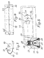
- Figure 1 shows a longitudinal section through a body which has a concave cavity which is elliptically curved in one direction and the surface of which is mirrored to form a mirror 1;
- the left and right mirror halves of the mirror 1 are designated by the reference numerals 2 and 3.
- the object 12 to be scanned is located in the plane, which is moved in the y-direction under the mirror 1.
- the mirror 1 has a slit-shaped opening 4 between the lamps 7, 7 ′ for masking out the imaging beam path 6 originating from the object 12 to the outside of the mirror 1.
- a deflecting mirror 5 is arranged along the same, which is inclined at 45 degrees for deflecting the imaging beam path 6, a lens 8 being located in the outer, deflected imaging beam path 6 ', in the image plane of which a line sensor 11 is arranged.
- a beam or color splitter 9 can be arranged in front of the line sensor 11, which splits the imaging beam path 6 ′ and directs it to further CCD line sensors 10.
- the mirror 1 can have an elongated blackened area 14 in the region of the apex and around the opening and the lamps 7, 7 '.
- the mirror 1 below the mirror halves 2 and 3 can be elongated, parallel to the opening 4 have blackened areas 13, 13 '; or these areas 13, 13 'can be roughened or structured non-reflecting, as can be seen in FIG. 2.
- the imaging beam path 6, 6 ' essentially consists of remitting components of the incident light from the lamps 7, 7'.
- the lighting maxima are on the edge of the image fields. This produces a distribution of the illuminance that is inverse to the shading of the lens, so that the overall sensitivity remains constant over the CCD line.
- the CCD line scanner or mirror 1 can be designed in a particularly small design according to FIGS. 1, 3 and 4 in a straight direction in an axial direction and in the cross-sectional plane perpendicular thereto as a partial ellipsoid or approximately as a partial ellipsoid, in which case the second focal line F2 , on which the object 12 is located in the plane, runs outside the mirror or reflector.
- FIG. 4 shows a technical embodiment of the lighting device according to the invention.
- a CCD line scanner consists of a reflector 17, which is elliptically curved in a cross-sectional plane and, in the vertical direction, is straight and elongated from a sheet metal or plastic part, the inner surface of which, as a mirror envelope, has half an ellipse 18 with the focal line F1 and is the outside focus line F2.
- the reflector 17 according to FIG. 4 has a longitudinal slot 19.
- the reflector 17 has longitudinally extending legs 21, 21 ′ which are bent over by approximately 90 degrees and in which bores 22 are arranged for fastening the reflector 17.
- FIG. 5 shows the arrangement of the reflector 17 within a complete lighting device, consisting of a holding element 34, which can be designed in a bow-shaped manner, also consisting of two brackets, and in which the reflector 17 is mounted.
- a holding element 34 On the inner focus line F1 of the reflector 17 and thus within it are two lamps 23, each of which is suspended from a lamp holder 28, both of which are fastened on the holding element 34 or holding elements are.
- the lamp holders 28 as well as the one or more holding elements 34 are designed such that the imaging beam path through the longitudinal slot 19 can fall onto a longitudinal mirror 29 located above the reflector 17 between the lamp holders 28, which deflects the imaging beam path onto a lens 30. From there, the redirected beam falls on a CCD line 31 or CCD matrix.
- a semi-transparent deflecting mirror 33 can be arranged within the imaging beam path after the objective 30, which deflects part of the beam path via a filter onto a further CCD line 32.
- a lamp backdrop 24 which causes shadowing of the light which projects from the lamps 23 downwards in a projection perpendicular to the object.
- This shading can be formed by a projection or a nose, which is arranged in a projecting manner on the scenes 24, the noses on the lamp scenes 24 being directed towards one another and in the vertical projection just the direct beam path of the lamps 23 downward on the Shade the object to avoid directly emitted light.
- a cover glass frame 26 is arranged below the reflector 17 and holds a cover glass 25 at the end of the reflector 17.
- an aperture 27 can be arranged on or below the cover slip 25.
- the cover slip frame 26 is screwed together with the reflector 17 by means of screws to the holding element or elements 34.
- the one or more holding elements 34 are held on a support frame 35, which also encloses the electrical and optical parts.
- the CCD line scanner according to the invention for the optical-electrical scanning of an object is particularly suitable for being used for the automatic detection of receipts or check cards, because it is used for reflections such as those from rapidly moving ( " fluttering") and shiny receipts Example checks or check cards that are generated are excluded.
Landscapes
- Engineering & Computer Science (AREA)
- Multimedia (AREA)
- Signal Processing (AREA)
- Physics & Mathematics (AREA)
- Electromagnetism (AREA)
- Toxicology (AREA)
- Health & Medical Sciences (AREA)
- General Health & Medical Sciences (AREA)
- Optics & Photonics (AREA)
- Artificial Intelligence (AREA)
- Computer Vision & Pattern Recognition (AREA)
- General Physics & Mathematics (AREA)
- Theoretical Computer Science (AREA)
- Facsimile Scanning Arrangements (AREA)
- Image Input (AREA)
- Inspection Of Paper Currency And Valuable Securities (AREA)
- Character Input (AREA)
Applications Claiming Priority (2)
| Application Number | Priority Date | Filing Date | Title |
|---|---|---|---|
| DE19535098A DE19535098C2 (de) | 1995-09-21 | 1995-09-21 | CCD-Zeilenscanner zum optisch-elektrischen Abtasten eines Objektes |
| DE19535098 | 1995-09-21 |
Publications (3)
| Publication Number | Publication Date |
|---|---|
| EP0764867A2 true EP0764867A2 (fr) | 1997-03-26 |
| EP0764867A3 EP0764867A3 (fr) | 1997-09-17 |
| EP0764867B1 EP0764867B1 (fr) | 2000-12-13 |
Family
ID=7772781
Family Applications (1)
| Application Number | Title | Priority Date | Filing Date |
|---|---|---|---|
| EP96115252A Expired - Lifetime EP0764867B1 (fr) | 1995-09-21 | 1996-09-23 | Dispositif de balayage en ligne CCD pour le balayage opto-électronique d'un objet |
Country Status (3)
| Country | Link |
|---|---|
| EP (1) | EP0764867B1 (fr) |
| DE (2) | DE19535098C2 (fr) |
| ES (1) | ES2154374T3 (fr) |
Families Citing this family (1)
| Publication number | Priority date | Publication date | Assignee | Title |
|---|---|---|---|---|
| DE10000030A1 (de) | 2000-01-03 | 2001-07-05 | Giesecke & Devrient Gmbh | Kamerasystem für die Bearbeitung von Dokumenten |
Family Cites Families (3)
| Publication number | Priority date | Publication date | Assignee | Title |
|---|---|---|---|---|
| GB1586572A (en) * | 1977-05-31 | 1981-03-18 | Xerox Corp | Optical illuminating systems |
| US4220978A (en) * | 1977-07-08 | 1980-09-02 | Burroughs Corporation | Electro-optical document reader |
| US4422100A (en) * | 1982-03-08 | 1983-12-20 | The Mead Corporation | Document scanning apparatus |
-
1995
- 1995-09-21 DE DE19535098A patent/DE19535098C2/de not_active Expired - Fee Related
-
1996
- 1996-09-23 DE DE59606207T patent/DE59606207D1/de not_active Expired - Lifetime
- 1996-09-23 EP EP96115252A patent/EP0764867B1/fr not_active Expired - Lifetime
- 1996-09-23 ES ES96115252T patent/ES2154374T3/es not_active Expired - Lifetime
Non-Patent Citations (1)
| Title |
|---|
| None |
Also Published As
| Publication number | Publication date |
|---|---|
| EP0764867A3 (fr) | 1997-09-17 |
| ES2154374T3 (es) | 2001-04-01 |
| DE19535098A1 (de) | 1997-03-27 |
| DE19535098C2 (de) | 1999-08-26 |
| DE59606207D1 (de) | 2001-01-18 |
| EP0764867B1 (fr) | 2000-12-13 |
Similar Documents
| Publication | Publication Date | Title |
|---|---|---|
| DE102014203335A1 (de) | Lichtmodul eines Kraftfahrzeugscheinwerfers und Scheinwerfer mit einem solchen Lichtmodul | |
| DE60032903T2 (de) | Kondensierendes und sammelndes optisches system, welches parabolreflektoren oder ein korrespondierendes elliptisch-hyperboloid-förmiges reflektorpaar verwendet | |
| DE3534019A1 (de) | Optische bahnueberwachungsvorrichtung | |
| DE3424211C2 (fr) | ||
| DE1497507C3 (de) | Optische Vorrichtung zum Projizieren einer Abbildung eines Objektes | |
| DE3804534C2 (de) | Spiegelsystem mit einem sammelnden Primärspiegel | |
| DE1472288B2 (de) | Schreibprojektor | |
| DE3151221A1 (de) | "abtastobjektiv fuer abtastung mit gleichmaessiger geschwindigkeit mit hohem aufloesungsvermoegen" | |
| DE4426968A1 (de) | Lichtleiter, vorzugsweise zur seitlichen Beleuchtung eines Objektes | |
| EP1483622B1 (fr) | Surface de support d'un appareil destine a la prise de vues optique d'objets | |
| EP0764867A2 (fr) | Dispositif de balayage en ligne CCD pour le balayage opto-électronique d'un objet | |
| DE3033758C2 (fr) | ||
| EP1507228B1 (fr) | Lecteur de codes optiques | |
| DE2623231A1 (de) | Optische einrichtung zur erfassung des von gluehlampen abgestrahlten lichtes | |
| DE3708647C2 (fr) | ||
| EP0199976B1 (fr) | Dispositif d'éclairage pour lecture automatique | |
| EP0603703B1 (fr) | Appareil de lecture | |
| DE19813126B4 (de) | Filmabtaster mit Prisma zur Abtastung der Perforationslöcher | |
| DE9202306U1 (de) | Beleuchtungseinrichtung, insbesondere für Bildverarbeitungssysteme | |
| DE1950423A1 (de) | Spiegelkondensor | |
| DE19925225A1 (de) | Vorlagenlesegerät und Lichtquellenbaugruppe hierfür | |
| DE19813124B4 (de) | Filmabtaster mit optisch durchlässigen Führungselementen | |
| DE1772064C2 (de) | Optisches Meßgerät | |
| DE700698C (de) | Vorrichtung zur Beleuchtung der gekruemmten spiegeoptischen Abbildung | |
| DE69328094T2 (de) | Abtastgerät |
Legal Events
| Date | Code | Title | Description |
|---|---|---|---|
| PUAI | Public reference made under article 153(3) epc to a published international application that has entered the european phase |
Free format text: ORIGINAL CODE: 0009012 |
|
| AK | Designated contracting states |
Kind code of ref document: A2 Designated state(s): CH DE ES FR GB IT LI |
|
| PUAL | Search report despatched |
Free format text: ORIGINAL CODE: 0009013 |
|
| AK | Designated contracting states |
Kind code of ref document: A3 Designated state(s): CH DE ES FR GB IT LI |
|
| 17P | Request for examination filed |
Effective date: 19980209 |
|
| RAP1 | Party data changed (applicant data changed or rights of an application transferred) |
Owner name: BAUMER OPTRONIC GMBH |
|
| 17Q | First examination report despatched |
Effective date: 19990405 |
|
| GRAG | Despatch of communication of intention to grant |
Free format text: ORIGINAL CODE: EPIDOS AGRA |
|
| GRAG | Despatch of communication of intention to grant |
Free format text: ORIGINAL CODE: EPIDOS AGRA |
|
| GRAH | Despatch of communication of intention to grant a patent |
Free format text: ORIGINAL CODE: EPIDOS IGRA |
|
| 17Q | First examination report despatched |
Effective date: 19990405 |
|
| GRAH | Despatch of communication of intention to grant a patent |
Free format text: ORIGINAL CODE: EPIDOS IGRA |
|
| GRAA | (expected) grant |
Free format text: ORIGINAL CODE: 0009210 |
|
| AK | Designated contracting states |
Kind code of ref document: B1 Designated state(s): CH DE ES FR GB IT LI |
|
| REG | Reference to a national code |
Ref country code: CH Ref legal event code: EP |
|
| GBT | Gb: translation of ep patent filed (gb section 77(6)(a)/1977) |
Effective date: 20001213 |
|
| REF | Corresponds to: |
Ref document number: 59606207 Country of ref document: DE Date of ref document: 20010118 |
|
| ITF | It: translation for a ep patent filed | ||
| REG | Reference to a national code |
Ref country code: CH Ref legal event code: NV Representative=s name: FREI PATENTANWALTSBUERO |
|
| REG | Reference to a national code |
Ref country code: ES Ref legal event code: FG2A Ref document number: 2154374 Country of ref document: ES Kind code of ref document: T3 |
|
| ET | Fr: translation filed | ||
| PLBE | No opposition filed within time limit |
Free format text: ORIGINAL CODE: 0009261 |
|
| STAA | Information on the status of an ep patent application or granted ep patent |
Free format text: STATUS: NO OPPOSITION FILED WITHIN TIME LIMIT |
|
| 26N | No opposition filed | ||
| REG | Reference to a national code |
Ref country code: GB Ref legal event code: IF02 |
|
| PGFP | Annual fee paid to national office [announced via postgrant information from national office to epo] |
Ref country code: ES Payment date: 20030929 Year of fee payment: 8 |
|
| PGFP | Annual fee paid to national office [announced via postgrant information from national office to epo] |
Ref country code: CH Payment date: 20030930 Year of fee payment: 8 |
|
| PG25 | Lapsed in a contracting state [announced via postgrant information from national office to epo] |
Ref country code: ES Free format text: LAPSE BECAUSE OF NON-PAYMENT OF DUE FEES Effective date: 20040924 |
|
| PG25 | Lapsed in a contracting state [announced via postgrant information from national office to epo] |
Ref country code: LI Free format text: LAPSE BECAUSE OF NON-PAYMENT OF DUE FEES Effective date: 20040930 Ref country code: CH Free format text: LAPSE BECAUSE OF NON-PAYMENT OF DUE FEES Effective date: 20040930 |
|
| REG | Reference to a national code |
Ref country code: CH Ref legal event code: PL |
|
| REG | Reference to a national code |
Ref country code: ES Ref legal event code: FD2A Effective date: 20040924 |
|
| PGFP | Annual fee paid to national office [announced via postgrant information from national office to epo] |
Ref country code: FR Payment date: 20080918 Year of fee payment: 13 |
|
| PGFP | Annual fee paid to national office [announced via postgrant information from national office to epo] |
Ref country code: GB Payment date: 20080917 Year of fee payment: 13 |
|
| PGFP | Annual fee paid to national office [announced via postgrant information from national office to epo] |
Ref country code: IT Payment date: 20080926 Year of fee payment: 13 |
|
| GBPC | Gb: european patent ceased through non-payment of renewal fee |
Effective date: 20090923 |
|
| REG | Reference to a national code |
Ref country code: FR Ref legal event code: ST Effective date: 20100531 |
|
| PG25 | Lapsed in a contracting state [announced via postgrant information from national office to epo] |
Ref country code: FR Free format text: LAPSE BECAUSE OF NON-PAYMENT OF DUE FEES Effective date: 20090930 |
|
| PG25 | Lapsed in a contracting state [announced via postgrant information from national office to epo] |
Ref country code: GB Free format text: LAPSE BECAUSE OF NON-PAYMENT OF DUE FEES Effective date: 20090923 |
|
| PGFP | Annual fee paid to national office [announced via postgrant information from national office to epo] |
Ref country code: DE Payment date: 20101126 Year of fee payment: 15 |
|
| PG25 | Lapsed in a contracting state [announced via postgrant information from national office to epo] |
Ref country code: IT Free format text: LAPSE BECAUSE OF NON-PAYMENT OF DUE FEES Effective date: 20090923 |
|
| REG | Reference to a national code |
Ref country code: DE Ref legal event code: R119 Ref document number: 59606207 Country of ref document: DE Effective date: 20120403 |
|
| PG25 | Lapsed in a contracting state [announced via postgrant information from national office to epo] |
Ref country code: DE Free format text: LAPSE BECAUSE OF NON-PAYMENT OF DUE FEES Effective date: 20120403 |