EP0765093A2 - Procédé pour la détection de situations de surcharge dans des modules de raccordement de postes d'abonné d'un système de communication - Google Patents
Procédé pour la détection de situations de surcharge dans des modules de raccordement de postes d'abonné d'un système de communication Download PDFInfo
- Publication number
- EP0765093A2 EP0765093A2 EP96113852A EP96113852A EP0765093A2 EP 0765093 A2 EP0765093 A2 EP 0765093A2 EP 96113852 A EP96113852 A EP 96113852A EP 96113852 A EP96113852 A EP 96113852A EP 0765093 A2 EP0765093 A2 EP 0765093A2
- Authority
- EP
- European Patent Office
- Prior art keywords
- overload
- utilization
- measured
- communication
- gzs
- Prior art date
- Legal status (The legal status is an assumption and is not a legal conclusion. Google has not performed a legal analysis and makes no representation as to the accuracy of the status listed.)
- Granted
Links
Images

Classifications
-
- H—ELECTRICITY
- H04—ELECTRIC COMMUNICATION TECHNIQUE
- H04Q—SELECTING
- H04Q11/00—Selecting arrangements for multiplex systems
- H04Q11/04—Selecting arrangements for multiplex systems for time-division multiplexing
- H04Q11/0428—Integrated services digital network, i.e. systems for transmission of different types of digitised signals, e.g. speech, data, telecentral, television signals
-
- H—ELECTRICITY
- H04—ELECTRIC COMMUNICATION TECHNIQUE
- H04Q—SELECTING
- H04Q2213/00—Indexing scheme relating to selecting arrangements in general and for multiplex systems
- H04Q2213/13096—Digital apparatus individually associated with a subscriber line, digital line circuits
-
- H—ELECTRICITY
- H04—ELECTRIC COMMUNICATION TECHNIQUE
- H04Q—SELECTING
- H04Q2213/00—Indexing scheme relating to selecting arrangements in general and for multiplex systems
- H04Q2213/13103—Memory
-
- H—ELECTRICITY
- H04—ELECTRIC COMMUNICATION TECHNIQUE
- H04Q—SELECTING
- H04Q2213/00—Indexing scheme relating to selecting arrangements in general and for multiplex systems
- H04Q2213/13106—Microprocessor, CPU
-
- H—ELECTRICITY
- H04—ELECTRIC COMMUNICATION TECHNIQUE
- H04Q—SELECTING
- H04Q2213/00—Indexing scheme relating to selecting arrangements in general and for multiplex systems
- H04Q2213/13164—Traffic (registration, measurement,...)
-
- H—ELECTRICITY
- H04—ELECTRIC COMMUNICATION TECHNIQUE
- H04Q—SELECTING
- H04Q2213/00—Indexing scheme relating to selecting arrangements in general and for multiplex systems
- H04Q2213/13166—Fault prevention
-
- H—ELECTRICITY
- H04—ELECTRIC COMMUNICATION TECHNIQUE
- H04Q—SELECTING
- H04Q2213/00—Indexing scheme relating to selecting arrangements in general and for multiplex systems
- H04Q2213/13176—Common channel signaling, CCS7
-
- H—ELECTRICITY
- H04—ELECTRIC COMMUNICATION TECHNIQUE
- H04Q—SELECTING
- H04Q2213/00—Indexing scheme relating to selecting arrangements in general and for multiplex systems
- H04Q2213/13204—Protocols
-
- H—ELECTRICITY
- H04—ELECTRIC COMMUNICATION TECHNIQUE
- H04Q—SELECTING
- H04Q2213/00—Indexing scheme relating to selecting arrangements in general and for multiplex systems
- H04Q2213/1332—Logic circuits
Definitions
- Program-controlled communication systems have a central controller and subscriber connection modules connected to it, by means of which communication connections are implemented for connecting communication terminals.
- a subscriber line module provides 24 communication lines to which at least 24 communication terminals can be connected.
- a signaling channel - known in the art as a D channel - with, for example, a standardized transmission capacity of 16 kbit / s is routed via each of these communication connections. Signaling messages are transmitted both to the communication terminal and to the communication system via the signaling channel.
- a considerably higher flow of signaling messages from the communication system to the communication terminals occurs. This can lead to an excessive flow of signaling messages to the communication terminal, and thus to an overload of the subscriber line modules, in particular for certain uses of the communication terminal.
- the subscriber line modules each have a microprocessor system, with the aid of which the processing requests transmitted by the processes implemented in the subscriber line modules are processed.
- the processes are organized as independent tasks, which have different priority levels with regard to message processing.
- the resource processing capacity of the Microprocessor system is provided within a subscriber line module for message processing in interprocess communication and for resource management of the other resources on the subscriber line module. An overload of the microprocessor system is caused both by a considerable flood of messages in the direction of communication terminals and by the messages to be transmitted to the central control.
- a known method of determining the overload of a subscriber line module is to use the number of free memory elements of a memory element pool managed by the operating system.
- the storage elements are temporarily assigned to the respective processes or tasks for intermediate storage before information, i.e. the respective process can save its data or information on the memory elements assigned to it.
- the object on which the invention is based is to design a method for detecting an overload of a subscriber line module in such a way that a general fault condition or failure of the subscriber line module is avoided after detection by targeted countermeasures.
- the object is achieved by the features of patent claim 1.
- the essential aspect of the method according to the invention is to be seen in that, in order to detect an overload, the load on the microprocessor system, the signaling channels directed to the communication terminals and the memory element pool is measured continuously, and the overload of the subscriber line module is detected by comparing the measured loads with predetermined load limits.
- targeted or general, fast-acting countermeasures can be initiated.
- One of these countermeasures can be seen, for example, in the fact that the formation and transmission of signaling messages, which significantly influence the processor processing resources, is restricted to the communication devices causing a flood of signaling messages.
- those communication terminals to which the greatest number of signaling messages are currently being transmitted and a corresponding countermeasure, namely no longer to transmit all signaling messages, can be specifically determined.
- individual or all communication connections can be taken out of operation in order to avoid a currently pending overload of the respective subscriber line module - claims 16 and 17.
- overload levels are advantageously identified by comparing the measured workloads with different, predetermined load limits - claim 2.
- This overload strategy is useful in a multi-level countermeasure strategy, the individual countermeasures representing part or parts of an overall strategy.
- the subscriber line module is overloaded detected when the measured workloads are exceeded above the specified workload limits. Consequently, falling below the predetermined utilization limits constitutes a normal load - claim 3. In order to suppress extremely short-term overloads and incorrect measurements, exceeding or falling below utilization limits is only determined if these are measured within a predetermined time interval - claim 4.
- the utilization of the microprocessor system is advantageously determined by the number of idle tasks processed within a predetermined time interval. If the measured number falls below a predetermined number of idle tasks representing the load limit, an overload of the microprocessor system is detected - claim 5. The number of idle tasks is advantageously detected by a counter - claim 6.
- the utilization of the signaling channel is measured particularly advantageously by determining an overall message length.
- the message lengths of the individual signaling messages are recorded for each signaling channel and summed to form a total message length. If this total message length exceeds a limit message length representing the utilization limit within a time interval, the overload is recognized by the signaling to the communication terminals.
- a first overload state of a subscriber line module is determined when the load limits are constantly exceeded within a overload interval.
- a message indicating the first overload condition is formed - claim 8. This additional measure avoids the initiation of countermeasures in the event of a short-term violation individual utilization limits and when they are identified, targeted countermeasures can be initiated.
- the overload of the memory element pool is advantageously determined by measuring the memory elements that are still free.
- the measured free memory elements are compared with a predetermined number representing the utilization limit, and if the number falls below the predetermined number, an overload of the memory element pool is determined - claim 9.
- the utilization of the memory element pool is advantageously measured after each transmission of a signaling message to a connected communication terminal - claim 10 This point in time is advantageous because if the utilization limit is exceeded, further transmission of messages can be avoided.
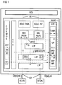
- Communication terminals KE can be connected to the communication system KS or the subscriber line module SLMO.
- the communication terminals KE are operated in the stimulus method (S) - all settings of the communication terminal KE are made from the communication system KS - or according to a protocol method (P) - after transmitting a signaling message si, the communication terminal KE independently carries out the settings.
- the signaling messages si are transmitted via a signaling channel D, each via a communication connection KA, together with the useful information ni, for example digitized voice information.
- the subscriber line module SLMO is connected to a control device CCU that coordinates and controls the communication system KS. 1 further shows the program structure of the subscriber line module SLMO shown as an example, a similar program structure being implemented in the other subscriber line modules SLMO (not shown).
- the program structure is structured in various processes explained below. The processes are organized as independent tasks, which have different priority levels with regard to message processing - messages from the central control device CCU or from the communication terminals KE or to these.
- HDLC TASK Communication between the central control device CCU and the subscriber line module SLMO is implemented in this by the two HDLC transmission routines HDLC TASK, HDLC INT.
- Both HDLC transmission routines HDLC TASK, HDLC INT contain driver routines for message traffic, the first HDLC transmission routine HDLC TASK for sending messages m to the central control unit CCU and the second HDLC transmission routine HDLC INT for receiving Messages m from the central control unit CCU is responsible.
- the requirements of the HDLC transmission routines HDLC TASK, HDLC INT are processed with the highest priority.
- the two HDLC transmission routines HDLC TASK, HDLC INT communicate with an apron device handler VDH, in which a processing preprocessing (call processing) of the signaling information si transmitted by the communication terminals KE is carried out.
- a processing preprocessing call processing
- the apron device handler VDH is a process realized by a program module IWU-S for the preprocessing of switching procedures of a stimulus communication terminal KE (S) and further a process realized by a program IWU-S0 for processing the switching messages a "protocol" communication terminal KE (P) - for example an ISDN communication terminal with an S0 interface - is provided.
- a layer 3 program L3P which communicates in particular with the program IWU-S via a defined interface IS, is included in particular for the formation of special messages for the display devices of stimulus communication terminals KE (S).
- the layer 3 program L3P is preferably provided for the formation and handling of display messages for all stimulus communication terminals KE (S) connected to the respective subscriber line module SLMO, the information content of these display messages being visual in the respective stimulus communication terminals KE in a display device is shown.
- layer 2 is implemented according to the OSI reference model for user network signaling and information transfer both in the direction of the central control device CCU and in the direction of the communication terminals KE. This layer 2 takes over for the layer 3, ie the network layer, the secure transmission of the signaling information si in both directions.
- the layer 2 program L2P communicates with a layer 1 program L1P, which represents the link to the circuitry transmission and power supply devices for the respectively connected communication terminals KE.
- This layer 1 program L1P activates and deactivates the communication connections KA, controls test loops and performs power management.
- An operating system COSMOS is implemented for the administration and operation of the microprocessor system resources.
- This operating system COSMOS also manages the memory elements SE of a memory element pool SEP and temporarily allocates them to the respective processes or program modules, as required - in particular for message processing - the memory element pool SEP with its memory elements SE is indicated by a dashed rectangle in the operating system block.
- a counter Z is provided in the operating system COSMOS, with the aid of which the still free memory elements SE of the memory element pool SEP are counted.
- a safety and operating technology program module STB For operational control, i.e. The operational settings of the SLMO subscriber connection module are provided by a safety and operating technology program module STB.
- This operating technology program module STB also provides all operating parameters with regard to the load limits required for overload detection. These are, in particular, operating parameters via a microprocessor system utilization limit GZS, the total limit message length gznl, and the interval times IV and a memory element pool utilization limit GZ.
- the message lengths L of the signaling messages si to be transmitted in each case in the direction of the communication terminal KE are ascertained in the layer 2 program L2P and transmitted to an overload routine URL.
- the overload routine URL has a memory element pool measuring routine SEP-MR, a signaling channel measuring routine D-MR, an overload program UP and a communication port-related signaling channel measuring routine KAD-MR.
- the overload status is communicated in particular to the process implemented by the program IWU-S for the control of stimulus communication terminals KE (S) by level 1 and level 2 overload messages by 1.2.
- the overload messages By transmitting the overload messages by 1.2, the transmission of display messages to individual, particularly overloaded communication connections KA or to all or the transmission of all signaling messages si to individual or particularly overloaded communication connections KA is prevented.
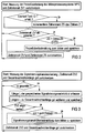
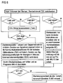
- FIGS. 2 to 6 The methods implemented in the measurement routines D-MR, SEP-MR and in the overload program UP are shown in FIGS. 2 to 6.
- the respective flowcharts are essentially self-explanatory and in particular show the method steps leading to the detection of an overload with regard to measuring the process load of the microprocessor MPS, measuring the signaling channel load, measuring the load of the memory element pool SEP, measuring the communication port-specific signaling channel load and one Detect overload, including different levels of overload.
- FIG. 1 The respective flowcharts are essentially self-explanatory and in particular show the method steps leading to the detection of an overload with regard to measuring the process load of the microprocessor MPS, measuring the signaling channel load, measuring the load of the memory element pool SEP, measuring the communication port-specific signaling channel load and one Detect overload, including different levels of overload.
Landscapes
- Engineering & Computer Science (AREA)
- Computer Networks & Wireless Communication (AREA)
- Exchange Systems With Centralized Control (AREA)
- Monitoring And Testing Of Exchanges (AREA)
Applications Claiming Priority (2)
| Application Number | Priority Date | Filing Date | Title |
|---|---|---|---|
| DE19534940A DE19534940C2 (de) | 1995-09-20 | 1995-09-20 | Verfahren zum Erkennen von Überlastsituationen in Teilnehmeranschlußmodulen eines Kommunikationssystems |
| DE19534940 | 1995-09-20 |
Publications (3)
| Publication Number | Publication Date |
|---|---|
| EP0765093A2 true EP0765093A2 (fr) | 1997-03-26 |
| EP0765093A3 EP0765093A3 (fr) | 2000-01-05 |
| EP0765093B1 EP0765093B1 (fr) | 2006-10-18 |
Family
ID=7772690
Family Applications (1)
| Application Number | Title | Priority Date | Filing Date |
|---|---|---|---|
| EP96113852A Expired - Lifetime EP0765093B1 (fr) | 1995-09-20 | 1996-08-29 | Procédé pour la détection de situations de surcharge dans des modules de raccordement de postes d'abonné d'un système de communication |
Country Status (4)
| Country | Link |
|---|---|
| US (1) | US5964840A (fr) |
| EP (1) | EP0765093B1 (fr) |
| CN (1) | CN1085455C (fr) |
| DE (1) | DE19534940C2 (fr) |
Cited By (1)
| Publication number | Priority date | Publication date | Assignee | Title |
|---|---|---|---|---|
| DE10056523A1 (de) * | 2000-11-15 | 2002-05-23 | Tenovis Gmbh & Co Kg | Verfahren zum Erzeugen von Gebühreninformationen in einem Telekommunikationsnetz |
Families Citing this family (3)
| Publication number | Priority date | Publication date | Assignee | Title |
|---|---|---|---|---|
| US6718170B1 (en) * | 1999-07-01 | 2004-04-06 | Qualcomm Incorporated | Dynamic allocation of microprocessor resources in a wireless communication device |
| US20020120702A1 (en) * | 2001-02-26 | 2002-08-29 | Schiavone Vincent J. | Method and apparatus for dynamic prioritization of electronic mail messages |
| US8954549B2 (en) * | 2010-06-07 | 2015-02-10 | Red Hat Israel, Ltd. | Automatic detection of a network interface on a host for accessing networked storage |
Family Cites Families (10)
| Publication number | Priority date | Publication date | Assignee | Title |
|---|---|---|---|---|
| DE3311912A1 (de) * | 1983-03-31 | 1984-10-11 | Siemens AG, 1000 Berlin und 8000 München | Schaltungsanordnung fuer fernmeldeanlagen, insbesondere fernsprechvermittlungsanlagen mit informationsverabeitenden schaltwerken und einrichtungen zur abwehr von ueberbelastungen |
| US4511762A (en) * | 1983-06-06 | 1985-04-16 | Siemens Corporate Research & Support, Inc. | Overload detection and control system for a telecommunications exchange |
| US4905171A (en) * | 1987-11-09 | 1990-02-27 | International Business Machines Corporation | Workstation controller performance monitor |
| DE4202816C1 (de) * | 1992-01-31 | 1993-09-30 | Siemens Ag | Fernsprechnebenstellenanlage mit Sammelanschluß |
| US5313454A (en) * | 1992-04-01 | 1994-05-17 | Stratacom, Inc. | Congestion control for cell networks |
| GB2278027B (en) * | 1993-04-19 | 1997-04-09 | Hewlett Packard Co | Methods and apparatus for monitoring networks |
| US5604866A (en) * | 1993-09-30 | 1997-02-18 | Silicon Graphics, Inc. | Flow control system having a counter in transmitter for decrementing and incrementing based upon transmitting and received message size respectively for indicating free space in receiver |
| US5574861A (en) * | 1993-12-21 | 1996-11-12 | Lorvig; Don | Dynamic allocation of B-channels in ISDN |
| JPH088971A (ja) * | 1994-06-20 | 1996-01-12 | Nec Corp | 分散型パケット交換機及びそのフロー制御実行制 御方法 |
| US5487072A (en) * | 1994-06-30 | 1996-01-23 | Bell Communications Research Inc. | Error monitoring algorithm for broadband signaling |
-
1995
- 1995-09-20 DE DE19534940A patent/DE19534940C2/de not_active Expired - Fee Related
-
1996
- 1996-08-29 EP EP96113852A patent/EP0765093B1/fr not_active Expired - Lifetime
- 1996-09-19 US US08/715,913 patent/US5964840A/en not_active Expired - Lifetime
- 1996-09-20 CN CN96112344A patent/CN1085455C/zh not_active Expired - Lifetime
Cited By (2)
| Publication number | Priority date | Publication date | Assignee | Title |
|---|---|---|---|---|
| DE10056523A1 (de) * | 2000-11-15 | 2002-05-23 | Tenovis Gmbh & Co Kg | Verfahren zum Erzeugen von Gebühreninformationen in einem Telekommunikationsnetz |
| DE10056523B4 (de) * | 2000-11-15 | 2006-06-01 | Tenovis Gmbh & Co. Kg | Verfahren zum Erzeugen von Gebühreninformationen in einem Telekommunikationsnetz |
Also Published As
| Publication number | Publication date |
|---|---|
| US5964840A (en) | 1999-10-12 |
| EP0765093A3 (fr) | 2000-01-05 |
| CN1151642A (zh) | 1997-06-11 |
| DE19534940A1 (de) | 1997-03-27 |
| EP0765093B1 (fr) | 2006-10-18 |
| DE19534940C2 (de) | 1998-07-02 |
| CN1085455C (zh) | 2002-05-22 |
Similar Documents
| Publication | Publication Date | Title |
|---|---|---|
| DE69632240T2 (de) | Verfahren und Anlage zur Kontrolle von Übertragungsgeschwindigkeiten von Quellen in ATM-Netzwerken | |
| DE69829759T2 (de) | Verteilung von nachrichten zu dienststeuereinrichtungen | |
| DE60132312T2 (de) | Lastregelung | |
| DE3300262C2 (fr) | ||
| DE69224403T2 (de) | Verfahren und System für die Überwachung der Paketrate in einem Paketnetz | |
| DE69529823T2 (de) | Verfahren zur überwachung des zustands eines verbindungsnetzes | |
| EP0470283B1 (fr) | Méthode et dispositif pour déterminer la qualité de circuits virtuels transitant par un dispositif de commutation ATM | |
| DE69838204T2 (de) | Integrierte Überlaststeuerung für verteilte Echtzeitsysteme | |
| DE69130910T2 (de) | Überlastungsregelungsverfahren für ISDN D Kanal | |
| EP0510222B1 (fr) | Procédé pour défense de surcharge dans un central d'un réseau de communication | |
| EP4070508B1 (fr) | Procédé, dispositif et système d'optimisation de la transmission de données entre des dispositifs de commande et des systèmes en nuage | |
| DE69908782T2 (de) | Fehlerkontrolle und -korrektur in einem datenkommunikationssystem | |
| DE69015165T2 (de) | Einrichtung zur Bewertung der Übertragungsqualität. | |
| DE69427320T2 (de) | Verfahren und Gerät zur Überwachung von Telekommunikationsnetzwerken | |
| EP0765093B1 (fr) | Procédé pour la détection de situations de surcharge dans des modules de raccordement de postes d'abonné d'un système de communication | |
| EP0360917A1 (fr) | Méthode et circuit pour la commande d'un circuit d'interface série | |
| DE4417777C2 (de) | Kommunikationssystem | |
| DE10325263A1 (de) | Sicherstellung von maximalen Reaktionszeiten in komplexen oder verteilten sicheren und/oder nicht sicheren Systemen | |
| DE19532929C2 (de) | Verfahren zur Verringerung von Alarmmeldungen in Lastsituationen | |
| DE3613898A1 (de) | Kommunikationssystem mit mehreren auf ein gemeinsames uebertragungsnetzwerk zugreifenden teilnehmerstationen | |
| EP1298840A1 (fr) | Gestion de la performance d'un réseau | |
| EP1001646B1 (fr) | Methode permettant de déterminer pour chaque connexion individuelle le débit actuellement admissible de transfert de cellules ATM | |
| EP1255378B1 (fr) | Adaptation de la taille de la fenêtre en fonction de la capacité en cas de surcharge I/O | |
| EP0380957B1 (fr) | Circuit pour centraux de télécommunications, en particulier centraux téléphoniques, avec des commutateurs à distance, des groupes de commutateurs distribués et des dispositifs de commutation centraux | |
| EP0477613A2 (fr) | Procédé pour la sélection uniforme des événements se produisent dans un système de communication |
Legal Events
| Date | Code | Title | Description |
|---|---|---|---|
| PUAI | Public reference made under article 153(3) epc to a published international application that has entered the european phase |
Free format text: ORIGINAL CODE: 0009012 |
|
| AK | Designated contracting states |
Kind code of ref document: A2 Designated state(s): BE FR GB NL |
|
| PUAL | Search report despatched |
Free format text: ORIGINAL CODE: 0009013 |
|
| AK | Designated contracting states |
Kind code of ref document: A3 Designated state(s): BE FR GB NL |
|
| RIC1 | Information provided on ipc code assigned before grant |
Free format text: 7H 04Q 3/545 A, 7H 04Q 11/04 B |
|
| 17P | Request for examination filed |
Effective date: 20000531 |
|
| GRAP | Despatch of communication of intention to grant a patent |
Free format text: ORIGINAL CODE: EPIDOSNIGR1 |
|
| GRAS | Grant fee paid |
Free format text: ORIGINAL CODE: EPIDOSNIGR3 |
|
| GRAA | (expected) grant |
Free format text: ORIGINAL CODE: 0009210 |
|
| AK | Designated contracting states |
Kind code of ref document: B1 Designated state(s): BE FR GB NL |
|
| PG25 | Lapsed in a contracting state [announced via postgrant information from national office to epo] |
Ref country code: NL Free format text: LAPSE BECAUSE OF FAILURE TO SUBMIT A TRANSLATION OF THE DESCRIPTION OR TO PAY THE FEE WITHIN THE PRESCRIBED TIME-LIMIT Effective date: 20061018 |
|
| REG | Reference to a national code |
Ref country code: GB Ref legal event code: FG4D Free format text: NOT ENGLISH |
|
| GBT | Gb: translation of ep patent filed (gb section 77(6)(a)/1977) |
Effective date: 20070104 |
|
| NLV1 | Nl: lapsed or annulled due to failure to fulfill the requirements of art. 29p and 29m of the patents act | ||
| ET | Fr: translation filed | ||
| PLBE | No opposition filed within time limit |
Free format text: ORIGINAL CODE: 0009261 |
|
| STAA | Information on the status of an ep patent application or granted ep patent |
Free format text: STATUS: NO OPPOSITION FILED WITHIN TIME LIMIT |
|
| 26N | No opposition filed |
Effective date: 20070719 |
|
| BERE | Be: lapsed |
Owner name: SIEMENS A.G. Effective date: 20070831 |
|
| PG25 | Lapsed in a contracting state [announced via postgrant information from national office to epo] |
Ref country code: BE Free format text: LAPSE BECAUSE OF NON-PAYMENT OF DUE FEES Effective date: 20070831 |
|
| REG | Reference to a national code |
Ref country code: GB Ref legal event code: 732E Free format text: REGISTERED BETWEEN 20090604 AND 20090610 |
|
| REG | Reference to a national code |
Ref country code: FR Ref legal event code: TP |
|
| REG | Reference to a national code |
Ref country code: FR Ref legal event code: PLFP Year of fee payment: 20 |
|
| PGFP | Annual fee paid to national office [announced via postgrant information from national office to epo] |
Ref country code: FR Payment date: 20150624 Year of fee payment: 20 |
|
| PGFP | Annual fee paid to national office [announced via postgrant information from national office to epo] |
Ref country code: GB Payment date: 20150728 Year of fee payment: 20 |
|
| REG | Reference to a national code |
Ref country code: GB Ref legal event code: PE20 Expiry date: 20160828 |
|
| PG25 | Lapsed in a contracting state [announced via postgrant information from national office to epo] |
Ref country code: GB Free format text: LAPSE BECAUSE OF EXPIRATION OF PROTECTION Effective date: 20160828 |