EP0765145B1 - Vorrichtung zum gebrauch in transplantationen von knochengewebe in einen knochenhohlraum - Google Patents
Vorrichtung zum gebrauch in transplantationen von knochengewebe in einen knochenhohlraum Download PDFInfo
- Publication number
- EP0765145B1 EP0765145B1 EP95919723A EP95919723A EP0765145B1 EP 0765145 B1 EP0765145 B1 EP 0765145B1 EP 95919723 A EP95919723 A EP 95919723A EP 95919723 A EP95919723 A EP 95919723A EP 0765145 B1 EP0765145 B1 EP 0765145B1
- Authority
- EP
- European Patent Office
- Prior art keywords
- compacting
- cavity
- bone
- compacting means
- tissue material
- Prior art date
- Legal status (The legal status is an assumption and is not a legal conclusion. Google has not performed a legal analysis and makes no representation as to the accuracy of the status listed.)
- Expired - Lifetime
Links
- 210000000988 bone and bone Anatomy 0.000 title claims abstract description 57
- 239000000463 material Substances 0.000 title claims abstract description 39
- 238000002054 transplantation Methods 0.000 title claims abstract description 24
- 238000005056 compaction Methods 0.000 claims description 11
- 239000007788 liquid Substances 0.000 claims description 11
- 238000006073 displacement reaction Methods 0.000 claims description 4
- 238000003780 insertion Methods 0.000 claims description 4
- 230000037431 insertion Effects 0.000 claims description 4
- 230000015572 biosynthetic process Effects 0.000 claims description 3
- 238000005755 formation reaction Methods 0.000 claims description 3
- 230000000694 effects Effects 0.000 description 5
- 210000001981 hip bone Anatomy 0.000 description 3
- 210000004394 hip joint Anatomy 0.000 description 3
- 206010065687 Bone loss Diseases 0.000 description 2
- 239000008280 blood Substances 0.000 description 2
- 210000004369 blood Anatomy 0.000 description 2
- 238000007596 consolidation process Methods 0.000 description 2
- 210000001519 tissue Anatomy 0.000 description 2
- 210000000689 upper leg Anatomy 0.000 description 2
- XLYOFNOQVPJJNP-UHFFFAOYSA-N water Substances O XLYOFNOQVPJJNP-UHFFFAOYSA-N 0.000 description 2
- 239000002639 bone cement Substances 0.000 description 1
- 230000001419 dependent effect Effects 0.000 description 1
- 238000000034 method Methods 0.000 description 1
- 238000012986 modification Methods 0.000 description 1
- 230000004048 modification Effects 0.000 description 1
- 239000002245 particle Substances 0.000 description 1
Images

Classifications
-
- A—HUMAN NECESSITIES
- A61—MEDICAL OR VETERINARY SCIENCE; HYGIENE
- A61B—DIAGNOSIS; SURGERY; IDENTIFICATION
- A61B17/00—Surgical instruments, devices or methods
- A61B17/56—Surgical instruments or methods for treatment of bones or joints; Devices specially adapted therefor
- A61B17/58—Surgical instruments or methods for treatment of bones or joints; Devices specially adapted therefor for osteosynthesis, e.g. bone plates, screws or setting implements
- A61B17/88—Osteosynthesis instruments; Methods or means for implanting or extracting internal or external fixation devices
- A61B17/885—Tools for expanding or compacting bones or discs or cavities therein
-
- A—HUMAN NECESSITIES
- A61—MEDICAL OR VETERINARY SCIENCE; HYGIENE
- A61F—FILTERS IMPLANTABLE INTO BLOOD VESSELS; PROSTHESES; DEVICES PROVIDING PATENCY TO, OR PREVENTING COLLAPSING OF, TUBULAR STRUCTURES OF THE BODY, e.g. STENTS; ORTHOPAEDIC, NURSING OR CONTRACEPTIVE DEVICES; FOMENTATION; TREATMENT OR PROTECTION OF EYES OR EARS; BANDAGES, DRESSINGS OR ABSORBENT PADS; FIRST-AID KITS
- A61F2/00—Filters implantable into blood vessels; Prostheses, i.e. artificial substitutes or replacements for parts of the body; Appliances for connecting them with the body; Devices providing patency to, or preventing collapsing of, tubular structures of the body, e.g. stents
- A61F2/02—Prostheses implantable into the body
- A61F2/30—Joints
- A61F2/46—Special tools for implanting artificial joints
- A61F2/4601—Special tools for implanting artificial joints for introducing bone substitute, for implanting bone graft implants or for compacting them in the bone cavity
-
- A—HUMAN NECESSITIES
- A61—MEDICAL OR VETERINARY SCIENCE; HYGIENE
- A61B—DIAGNOSIS; SURGERY; IDENTIFICATION
- A61B17/00—Surgical instruments, devices or methods
- A61B2017/0046—Surgical instruments, devices or methods with a releasable handle; with handle and operating part separable
-
- A—HUMAN NECESSITIES
- A61—MEDICAL OR VETERINARY SCIENCE; HYGIENE
- A61F—FILTERS IMPLANTABLE INTO BLOOD VESSELS; PROSTHESES; DEVICES PROVIDING PATENCY TO, OR PREVENTING COLLAPSING OF, TUBULAR STRUCTURES OF THE BODY, e.g. STENTS; ORTHOPAEDIC, NURSING OR CONTRACEPTIVE DEVICES; FOMENTATION; TREATMENT OR PROTECTION OF EYES OR EARS; BANDAGES, DRESSINGS OR ABSORBENT PADS; FIRST-AID KITS
- A61F2/00—Filters implantable into blood vessels; Prostheses, i.e. artificial substitutes or replacements for parts of the body; Appliances for connecting them with the body; Devices providing patency to, or preventing collapsing of, tubular structures of the body, e.g. stents
- A61F2/02—Prostheses implantable into the body
- A61F2/30—Joints
- A61F2/46—Special tools for implanting artificial joints
- A61F2/4603—Special tools for implanting artificial joints for insertion or extraction of endoprosthetic joints or of accessories thereof
-
- A—HUMAN NECESSITIES
- A61—MEDICAL OR VETERINARY SCIENCE; HYGIENE
- A61F—FILTERS IMPLANTABLE INTO BLOOD VESSELS; PROSTHESES; DEVICES PROVIDING PATENCY TO, OR PREVENTING COLLAPSING OF, TUBULAR STRUCTURES OF THE BODY, e.g. STENTS; ORTHOPAEDIC, NURSING OR CONTRACEPTIVE DEVICES; FOMENTATION; TREATMENT OR PROTECTION OF EYES OR EARS; BANDAGES, DRESSINGS OR ABSORBENT PADS; FIRST-AID KITS
- A61F2/00—Filters implantable into blood vessels; Prostheses, i.e. artificial substitutes or replacements for parts of the body; Appliances for connecting them with the body; Devices providing patency to, or preventing collapsing of, tubular structures of the body, e.g. stents
- A61F2/02—Prostheses implantable into the body
- A61F2/30—Joints
- A61F2/46—Special tools for implanting artificial joints
- A61F2/4603—Special tools for implanting artificial joints for insertion or extraction of endoprosthetic joints or of accessories thereof
- A61F2/4609—Special tools for implanting artificial joints for insertion or extraction of endoprosthetic joints or of accessories thereof of acetabular cups
-
- A—HUMAN NECESSITIES
- A61—MEDICAL OR VETERINARY SCIENCE; HYGIENE
- A61F—FILTERS IMPLANTABLE INTO BLOOD VESSELS; PROSTHESES; DEVICES PROVIDING PATENCY TO, OR PREVENTING COLLAPSING OF, TUBULAR STRUCTURES OF THE BODY, e.g. STENTS; ORTHOPAEDIC, NURSING OR CONTRACEPTIVE DEVICES; FOMENTATION; TREATMENT OR PROTECTION OF EYES OR EARS; BANDAGES, DRESSINGS OR ABSORBENT PADS; FIRST-AID KITS
- A61F2/00—Filters implantable into blood vessels; Prostheses, i.e. artificial substitutes or replacements for parts of the body; Appliances for connecting them with the body; Devices providing patency to, or preventing collapsing of, tubular structures of the body, e.g. stents
- A61F2/02—Prostheses implantable into the body
- A61F2/28—Bones
- A61F2002/2835—Bone graft implants for filling a bony defect or an endoprosthesis cavity, e.g. by synthetic material or biological material
-
- A—HUMAN NECESSITIES
- A61—MEDICAL OR VETERINARY SCIENCE; HYGIENE
- A61F—FILTERS IMPLANTABLE INTO BLOOD VESSELS; PROSTHESES; DEVICES PROVIDING PATENCY TO, OR PREVENTING COLLAPSING OF, TUBULAR STRUCTURES OF THE BODY, e.g. STENTS; ORTHOPAEDIC, NURSING OR CONTRACEPTIVE DEVICES; FOMENTATION; TREATMENT OR PROTECTION OF EYES OR EARS; BANDAGES, DRESSINGS OR ABSORBENT PADS; FIRST-AID KITS
- A61F2/00—Filters implantable into blood vessels; Prostheses, i.e. artificial substitutes or replacements for parts of the body; Appliances for connecting them with the body; Devices providing patency to, or preventing collapsing of, tubular structures of the body, e.g. stents
- A61F2/02—Prostheses implantable into the body
- A61F2/30—Joints
- A61F2/46—Special tools for implanting artificial joints
- A61F2002/4681—Special tools for implanting artificial joints by applying mechanical shocks, e.g. by hammering
Definitions
- This invention relates to a device for use in transplantation of bone tissue material in a cavity in bone, said device comprising means for compacting the bone tissue material in the cavity.
- a device comprising the features of the preamble of claim 1 is disclosed in EP-A-0 555 004.
- a particularly preferred application according to my prior Swedish patent applications relates to preparation of cavities in femurs as to receive a portion of a hip joint prosthesis.
- the invention thereby related to could be applied also in other cases where arbitrary prostheses, for example joint prostheses, are to be applied in a bone of the individual.
- the invention according to the present application as well as the invention aspects treated in my prior Swedish patent applications are based upon that a bone transplant formed by a bone tissue material is inserted into the cavity, said bone tissue being present in the bone transplant in the form of a plurality of small pieces or particles, i.e. in a ground or finely divided state.
- the bone tissue material is brought into a suitable consistency, such as paste or pulp.
- the bone tissue material then contains a suitable liquid.
- This liquid may comprise tissue liquid, such as blood.
- the liquid comprises suitably also water.
- the liquid may include fat, preferably in the form of living tissue.
- the present invention is based upon the knowledge of that the compacting of the bone tissue material into the cavity, which is of considerable importance for the transplantation, is difficult to accomplish as the bone transplant comprises fat and blood tends to flow into the bone transplant from the bottom side. As one then tries to accomplish the compaction of the bone transplant by means of the compacting means, said transplant tends to displace itself upwards along the sides of the compacting means instead of letting itself get compacted effectively deeper in the cavity.
- These problems are present in the application primarily related to according to my prior patent applications, that is for the preparation of cavities in femurs for the purpose of receiving hip joint prostheses, as well as in the application primarily foreseen in the present invention, that is bone transplantation in a joint socket.
- This joint socket may for instance be intended to receive the joint ball of a hip joint prosthesis.
- the object of the present invention is to further develop prior technique so that the compacting means is designed in a way to make it capable of exerting an effective compacting effect while avoiding the bone transplant from tending to get pressed out of the cavity along the sides to an unacceptable degree. It is emphasised that the compacting means thereby is intended to make bone transplantation possible in all sorts of present cavities in bones, i.e. not only joint sockets of the kind discussed above. Accordingly it is particularly noted that the invention here aimed at also can find its application at the compacting means cited in my Swedish patent applications 9200501-6 and 9300572-6.
- the object according to the invention is primarily provided for as the compacting means has a relief like structure on its compacting surface for contact with the bone tissue material.
- the object of this relief like structure is to obstruct the bones transplant from gliding or displacing along the compacting surface and going out of the cavity around the compacting means.
- the relief like structure will accordingly tend to act entrainingly upon the bone transplantation material.
- one here relates to a structure presenting ridges and recesses following each other alternatingly to make the compacting surface of the compacting means tend to entrain the transplantation material located nearest to the compacting means.
- the relief like structure is at least partly formed by grooves.
- the compacting means has a collar which extends fully or partly around the compacting surface to counteract displacement of transplantation material out of the cavity during the compaction.
- the compacting means according to the invention is provided in different sizes in accordance with the size of the cavity aimed at and the size of which will be defined by the compacting means, and, besides, the collar of the compacting means may also have a varying shape in accordance with the shape of the bone material portions surrounding the joint socket or other cavity which is to be repaired by means of a transplant.
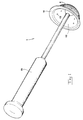
- the device according to the invention comprises a means 1 for the compaction of the bone tissue material in the cavity in question and more closely illustrated in the drawing figures.
- a joint socket in the hip bone of a patient is illustrated as a cavity 2.
- This joint socket has, through bone losses, been widened up to an undue degree and might even have been perforated somewhere, in general in the bottom of the socket.
- Fig 3 it is shown how the bone tissue material 3 may be compacted in the cavity 2 by means of the compacting means 1 to make the compacting means leave a joint socket in the hip bone after the execution of the compaction, said joint socket having a satisfactory wall thickness. After a certain period an intergrowth between the bone material of the hip bone and the transplantation material has taken place.
- the compacting means 1 has a relief like structure on its compacting surface 4 for contact with the bone tissue material 3.
- This relief structure comprises ridges 5 and recesses 6 having the task of acting entrainingly upon the transplantation material during the execution of the compaction.
- the ridges 5 and recesses 6 should at least partly be orientated on the compacting surface 4 to extend crossways or at least with an angle to the relative direction of movement between the compacting means and the bone transplantation material during the execution of the compaction for the obtaining of the discussed entraining effect upon the transplantation material.
- the relief like structure is at least partly formed as grooves which form said ridges and recesses respectively.
- the grooves extend generally transversely to the direction (arrow 7 in Fig 3) of insertion of the compacting means into the cavity 2.
- the compacting surface 4 of the compacting means forms a projection.
- the grooves 5, 6 extend fully or partly around the projection 4 on its outer surface. In practice it is preferred that the grooves extend circularly on the compacting surface 4 in planes generally perpendicular to the extension direction of the projection 4 and, accordingly, perpendicular to the direction (arrow 7) of insertion of the compacting means into the cavity 2.
- the projection has a generally part-spherical shape. More specifically, the projection 4 may have the character of a half sphere.
- the grooves form step formations with step surfaces 8 which to a major degree extend along the lengthwise axle 9 of the compacting means.
- the step formations further comprise step surfaces 10 which to a major degree extend radially in relation to the lengthwise axle 9 of the compacting means.
- the step surfaces 8 may be generally axially extending while the step surfaces 10 extend generally radially.
- variations are possible within the frame of the idea of the invention here aimed at; as can be seen in Fig 2, the angle between adjoining step surfaces 8 and 10 may vary. Through such a variation of angle the entraining effect of the compacting means to the transplantation material can be adapted as requested.
- the compacting surface 4 of the compacting means is defined by a jacket 11, which has an inner cavity 12.
- the jacket 11 is provided with openings 13 for allowing liquid to pass from the surrounding bone tissue material through the jacket 11 and into the cavity 12. From this cavity 12 the liquid can flow away thanks to the effect of the gravitational force or, alternatively, any known water suction equipment may be used to suck away the excessive liquid.
- the departure of liquid from the transplant means a consolidation of the same and a reduced tendency of the transplant to unintentionally diverge to the sides.
- the compacting means 1 has a collar 14, which extends fully or partly around the compacting surface 4 to counteract the displacement of transplantation material out of the cavity 2 during the compaction.
- the collar 14 has the character of a radially projecting flange and it may have, in correspondence with the intended use of the compacting means, different radial projection length out from the compacting surface 4 along the periphery of the latter.
- the very jacket 11 of the compacting means has the character of a hollow bowl.
- the compacting means 1 has a handle 15 which is fastened to the jacket 11 in the bottom of the cavity 12 of the latter.
- This handle 15 should be designed for allowing striking thereon to effectively press the compacting means against the bone transplant.
- the bone transplant is first arranged in the cavity 2 in question. Thereafter a compacting means with a shape suited for the purpose is chosen and the bone transplant is compacted by means of the compacting means to a required degree.
- the relief like structure on the compacting surface 4 of the compacting means reduces the tendency of the bone transplant to glide away and this effect is promoted by the collar 14 of the compacting means.
- a consolidation of the bone transplantation material takes place and the tendency thereof to unintentionally glide away along the sides of the compacting means from the bottom area in the cavity 2 during the compaction is reduced.
- the member for example a joint ball, which is to be received in the cavity can be arranged in its place and the operation be finished.
- a transplantation executed in this way can possibly immediately be subjected to a load via the joint ball, for example such load that arises during walking, or one can also, so as to be on the safe side, permit a certain period of intergrowth of the transplantation material before such loading.
- the idea of the invention is not at all constricted to compacting means with a shape suited for creating cavities suited for joint balls.
- the compacting means may have other shapes for the creation of other types of cavities in bones. Also other modifications are possible within the frame of the invention here related to.
Landscapes
- Health & Medical Sciences (AREA)
- Orthopedic Medicine & Surgery (AREA)
- Life Sciences & Earth Sciences (AREA)
- Animal Behavior & Ethology (AREA)
- Public Health (AREA)
- Engineering & Computer Science (AREA)
- Biomedical Technology (AREA)
- Heart & Thoracic Surgery (AREA)
- Surgery (AREA)
- Transplantation (AREA)
- Veterinary Medicine (AREA)
- General Health & Medical Sciences (AREA)
- Medical Informatics (AREA)
- Nuclear Medicine, Radiotherapy & Molecular Imaging (AREA)
- Physical Education & Sports Medicine (AREA)
- Molecular Biology (AREA)
- Cardiology (AREA)
- Oral & Maxillofacial Surgery (AREA)
- Vascular Medicine (AREA)
- Prostheses (AREA)
Claims (10)
- Ein Gerät zur Verwendung bei der Transplantation von Knochengewebsmaterial (3) in eine Knochenhöhle (2), wobei das besagte Gerät Mittel (1) zum Verdichten des Knochengewebsmaterials in der Höhle zum nachfolgenden Einsetzen einer Prothese in die Höhle umfaßt, und wobei das genannte Verdichtungsmittel (1) einen Stiel (15) umfaßt, dadurch gekennzeichnet, daß das Verdichtungsmittel auf seiner verdichtenden Oberfläche (4) eine reliefartige Struktur aufweist zum Kontakt mit dem Knochengewebsmaterial, um zu bezwecken, daß während des Verdichtens der Verdrängung des Knochengewebsmaterials entlang der verdichtenden Oberfläche und dem Entweichen des Knochengewebsmaterials aus der Höhle um das verdichtende Mittel herum entgegengewirkt wird.
- Ein Gerät nach Anspruch 1, dadurch gekennzeichnet, daß die reliefartige Struktur zumindest teilweise durch Rillen (5,6) gebildet wird.
- Ein Gerät nach Anspruch 2, dadurch gekennzeichnet, daß sich die Rillen (5,6) im großen und ganzen quer zu der Richtung der Einführung des Verdichtungsmittels in die Höhle erstrecken.
- Ein Gerät nach einem der Ansprüche 1 bis 3, dadurch gekennzeichnet, daß die verdichtende Oberfläche (4) des Verdichtungsmittels eine Erhebung bildet.
- Ein Gerät nach Anspruch 4, dadurch gekennzeichnet, daß sich die Rillen vollständig oder teilweise um die Erhebung herum erstrecken.
- Ein Gerät nach Anspruch 4, dadurch gekennzeichnet, daß die Erhebung eine im großen und ganzen teilsphärische Form hat.
- Ein Gerät nach einem der Ansprüche 2 bis 6, dadurch gekennzeichnet, daß die Rillen Stufengebilde mit Stufenflächen ausbilden (8; 10), welche sich sowohl im großen und ganzen in axialer Richtung als auch im großen und ganzen in radialer Richtung erstrecken, bezogen auf die von der verdichtenden Oberfläche (4) des Verdichtungsmittels gebildete Erhebung.
- Ein Gerät nach einem der vorangehenden Ansprüche, dadurch gekennzeichnet, daß die verdichtende Oberfläche (4) des Verdichtungsmittels (1) durch eine Glocke (11) bestimmt wird, die einen inneren Hohlraum (12) aufweist, und daß die Glocke mit Öffnungen (13) ausgestattet ist, welche das Einströmen von Flüssigkeit aus dem umgebenden Knochengewebsmaterial durch die Glocke hindurch und in den Hohlraum hinein ermöglichen.
- Ein Gerät nach einem der vorangehenden Ansprüche,
dadurch gekennzeichnet, daß das Verdichtungsmittel (1) einen Wulst (14) aufweist, der sich vollständig oder teilweise um eine verdichtende Oberfläche (4) herum erstreckt, um während des Verdichtens einer Verdrängung des Transplantationsmaterials aus der Höhle heraus entgegenzuwirken. - Ein Gerät nach Anspruch 8, dadurch gekennzeichnet, daß der Stiel (15) an der Glocke (11) des Verdichtungsmittels (1) im Boden des inneren Hohlraums (12 des Verdichtungsmittels (1) befestigt ist.
Applications Claiming Priority (3)
| Application Number | Priority Date | Filing Date | Title |
|---|---|---|---|
| SE9401683 | 1994-05-16 | ||
| SE9401683A SE509200C2 (sv) | 1994-05-16 | 1994-05-16 | Anordning för användning vid transplantation av benvävnadsmaterial i ett hålrum i ben |
| PCT/SE1995/000542 WO1995031159A1 (en) | 1994-05-16 | 1995-05-15 | A device for use in transplantation of bone tissue material in a cavity in bone |
Publications (2)
| Publication Number | Publication Date |
|---|---|
| EP0765145A1 EP0765145A1 (de) | 1997-04-02 |
| EP0765145B1 true EP0765145B1 (de) | 2001-12-19 |
Family
ID=20394020
Family Applications (1)
| Application Number | Title | Priority Date | Filing Date |
|---|---|---|---|
| EP95919723A Expired - Lifetime EP0765145B1 (de) | 1994-05-16 | 1995-05-15 | Vorrichtung zum gebrauch in transplantationen von knochengewebe in einen knochenhohlraum |
Country Status (6)
| Country | Link |
|---|---|
| US (1) | US5879355A (de) |
| EP (1) | EP0765145B1 (de) |
| AT (1) | ATE210945T1 (de) |
| DE (1) | DE69524753T2 (de) |
| SE (1) | SE509200C2 (de) |
| WO (1) | WO1995031159A1 (de) |
Families Citing this family (24)
| Publication number | Priority date | Publication date | Assignee | Title |
|---|---|---|---|---|
| SE503270C2 (sv) * | 1994-08-22 | 1996-04-29 | Harry Wexell | Kvarn, förfarande för tillverkning av bentransplantationsmaterial och användning av kvarn för sådan tillverkning |
| US6019765A (en) * | 1998-05-06 | 2000-02-01 | Johnson & Johnson Professional, Inc. | Morsellized bone allograft applicator device |
| RU2152764C1 (ru) * | 1999-12-07 | 2000-07-20 | Колесник Александр Иванович | Устройство для ориентирования положения чашки эндопротеза при эндопротезировании тазобедренного сустава |
| US7572259B2 (en) * | 2002-09-16 | 2009-08-11 | Greatbatch Ltd. | Inset acetabular reamer coupling |
| US7329284B2 (en) * | 2002-09-27 | 2008-02-12 | Depuy Products, Inc. | Concave resurfacing prosthesis |
| US8096300B2 (en) * | 2004-12-03 | 2012-01-17 | Dale Medical Products, Inc. | Endotracheal tube holder |
| US20090287309A1 (en) | 2007-01-30 | 2009-11-19 | Tornier Sas | Intra-articular joint replacement |
| FR2911773B1 (fr) | 2007-01-30 | 2009-03-27 | Tornier Sas | Methode et ensemble d'instrumentation chirurgicale pour poser une prothese totale d'epaule inversee,et prothese correspondante |
| US8556897B2 (en) * | 2007-02-09 | 2013-10-15 | Christopher G. Sidebotham | Modular spherical hollow reamer assembly for medical applications |
| CA2781407A1 (en) | 2008-01-14 | 2009-07-23 | Michael P. Brenzel | Apparatus and methods for fracture repair |
| WO2011088172A1 (en) | 2010-01-15 | 2011-07-21 | Brenzel Michael P | Rotary-rigid orthopaedic rod |
| ES2733729T3 (es) | 2010-01-20 | 2019-12-02 | Conventus Orthopaedics Inc | Aparato para el acceso a huesos y para la preparación de cavidades |
| CN107569279A (zh) | 2010-03-08 | 2018-01-12 | 康文图斯整形外科公司 | 用于骨修复的装置及方法 |
| US9408652B2 (en) * | 2010-04-27 | 2016-08-09 | Tornier Sas | Intra-articular joint replacement and method |
| DE102010054663B3 (de) * | 2010-12-15 | 2012-06-28 | Heraeus Medical Gmbh | Formwerkzeug zum Ausformen einer Hüftpfanne |
| EP2704651A4 (de) * | 2011-05-03 | 2014-10-08 | Smith & Nephew Inc | Patientenspezifische führungen für orthopädische implantate |
| US10022132B2 (en) | 2013-12-12 | 2018-07-17 | Conventus Orthopaedics, Inc. | Tissue displacement tools and methods |
| GB201322237D0 (en) | 2013-12-16 | 2014-01-29 | Depuy Ireland Ltd | Surgical reamer |
| US10092304B2 (en) | 2014-09-30 | 2018-10-09 | Depuy Ireland Unlimited Company | Orthopaedic surgical instrument assembly for reaming a patient's acetabulum |
| US10543003B2 (en) | 2014-09-30 | 2020-01-28 | Depuy Ireland Unlimited Company | Orthopaedic surgical instrument assembly and method of manufacturing same |
| US9675364B2 (en) | 2014-09-30 | 2017-06-13 | Depuy Ireland Unlimited Company | Grater and trial liner |
| US10631881B2 (en) | 2017-03-09 | 2020-04-28 | Flower Orthopedics Corporation | Plating depth gauge and countersink instrument |
| US10918426B2 (en) | 2017-07-04 | 2021-02-16 | Conventus Orthopaedics, Inc. | Apparatus and methods for treatment of a bone |
| WO2021050214A1 (en) * | 2019-09-11 | 2021-03-18 | Cedars-Sinai Medical Center | Apparatus and method for forming a custom cement-on-cement articulating hip spacer |
Family Cites Families (17)
| Publication number | Priority date | Publication date | Assignee | Title |
|---|---|---|---|---|
| DE2543723C3 (de) * | 1975-10-01 | 1978-04-06 | Aesculap-Werke Ag Vormals Jetter & Scheerer, 7200 Tuttlingen | Fräswerkzeug für chirurgische Zwecke |
| US4662891A (en) * | 1983-11-21 | 1987-05-05 | Joint Medical Products Corporation | Fixation elements for artificial joints |
| US4919153A (en) * | 1988-10-11 | 1990-04-24 | Origin Medsystems, Inc. | Method and apparatus for removing pre-placed prosthetic joints and preparing for their replacement |
| US5116339A (en) * | 1990-07-11 | 1992-05-26 | Glock Steven R | Acetabular cup installation tool and method of installing an acetabular cup |
| US5047035A (en) * | 1990-08-10 | 1991-09-10 | Mikhail Michael W E | System for performing hip prosthesis revision surgery |
| US5080680A (en) * | 1990-09-04 | 1992-01-14 | Mikhail Michael W E | Femoral stem prosthesis with preapplied cement mantle |
| US5116165A (en) * | 1991-03-11 | 1992-05-26 | Othy, Inc. | Acetabular reamer cup |
| US5171313A (en) * | 1991-05-08 | 1992-12-15 | Othy, Inc. | Tool driver |
| GB9202248D0 (en) * | 1992-02-03 | 1992-03-18 | Howmedica | Prosthesis for attachement without bone cement and method of attaching |
| US5282864A (en) * | 1992-02-19 | 1994-02-01 | Joint Medical Products Corporation | Acetabular prosthesis having a metal socket bearing |
| SE510358C2 (sv) * | 1992-02-20 | 1999-05-17 | Goesta Ullmark | Anordning för användning vid transplantation av benvävnadsmaterial i ett hålrum i ben |
| US5358532A (en) * | 1992-06-16 | 1994-10-25 | Smith & Nephew Richards Inc. | Cementless acetabular cup |
| DE4236324C1 (de) * | 1992-10-28 | 1993-09-02 | Schott Glaswerke, 55122 Mainz, De | |
| GB9322327D0 (en) * | 1993-10-29 | 1993-12-15 | Howmedica | Method and apparatus for implanting an acetabular cup |
| US5443519A (en) * | 1993-04-22 | 1995-08-22 | Implex Corporation | Prosthetic ellipsoidal acetabular cup |
| US5383932A (en) * | 1993-04-27 | 1995-01-24 | Johnson & Johnson Professional, Inc. | Absorbable medullary plug |
| GB9416215D0 (en) * | 1994-08-11 | 1994-10-05 | Howmedica | Acetabular bone graft impactor |
-
1994
- 1994-05-16 SE SE9401683A patent/SE509200C2/sv not_active IP Right Cessation
-
1995
- 1995-05-15 US US08/737,612 patent/US5879355A/en not_active Expired - Fee Related
- 1995-05-15 EP EP95919723A patent/EP0765145B1/de not_active Expired - Lifetime
- 1995-05-15 DE DE69524753T patent/DE69524753T2/de not_active Expired - Fee Related
- 1995-05-15 AT AT95919723T patent/ATE210945T1/de not_active IP Right Cessation
- 1995-05-15 WO PCT/SE1995/000542 patent/WO1995031159A1/en not_active Ceased
Also Published As
| Publication number | Publication date |
|---|---|
| DE69524753D1 (de) | 2002-01-31 |
| SE509200C2 (sv) | 1998-12-14 |
| DE69524753T2 (de) | 2003-02-27 |
| WO1995031159A1 (en) | 1995-11-23 |
| SE9401683D0 (sv) | 1994-05-16 |
| SE9401683L (sv) | 1995-11-17 |
| EP0765145A1 (de) | 1997-04-02 |
| US5879355A (en) | 1999-03-09 |
| ATE210945T1 (de) | 2002-01-15 |
Similar Documents
| Publication | Publication Date | Title |
|---|---|---|
| US5879355A (en) | Device for use in transplantation of bone tissue material in a cavity in bone | |
| US7115146B2 (en) | Multipiece implants formed of bone material | |
| DE69323503T2 (de) | Prothese für zementfreie Befestigung | |
| US4488549A (en) | Pressurization of cement in bones | |
| EP0169978B1 (de) | Aus einem inneren Pfannenkörper und einer Aussenschale bestehende Endoprothese für eine Hüftgelenkspfanne | |
| US20020029084A1 (en) | Bone implants with central chambers | |
| US20060241763A1 (en) | Multipiece bone implant | |
| WO2005094735A2 (de) | Füllmittel und zuführvorrichtung zum ausbilden einer stützstruktur in einem knocheninnenraum | |
| JPH04501223A (ja) | 既設の補綴を除去する方法と装置 | |
| EP1296620B1 (de) | Mehrteilige implantate aus knochenmaterial | |
| EP0243585B1 (de) | In einem Knochenhohlraum zu implantierender Prothesenschaft und Prothese mit dem Schaft | |
| KR101063114B1 (ko) | 대퇴부의 골수강 내에 고정된 샤프트를 포함하는 힙 보철물 | |
| EP1208821A2 (de) | Knochentransplantatverdichter | |
| AU2004257400B9 (en) | Hip prosthesis provided with a shaft inserted into the femur | |
| EP0143847A1 (de) | Intramedulärer zapfen | |
| GB2192543A (en) | Peg for use in prosthetic devices | |
| DE19604458A1 (de) | Gelenkpfanne | |
| EP1316297A1 (de) | Vorrichtung zum Einbringen von Knochenzement in eine Spongiosa | |
| GB2104390A (en) | Pressurisation of cement in bones | |
| DE3714468A1 (de) | Kuenstliche hueftgelenkspfanne | |
| JPS6031708Y2 (ja) | 線付き髄内栓用のセメント充填具 | |
| HK1081096B (en) | Prosthesis fixation with mechanically compacted biocompatible granules | |
| HK1081096A1 (zh) | 具有机械压缩的生物相容性颗粒的假体固定元件 |
Legal Events
| Date | Code | Title | Description |
|---|---|---|---|
| PUAI | Public reference made under article 153(3) epc to a published international application that has entered the european phase |
Free format text: ORIGINAL CODE: 0009012 |
|
| 17P | Request for examination filed |
Effective date: 19961107 |
|
| AK | Designated contracting states |
Kind code of ref document: A1 Designated state(s): AT BE CH DE DK ES FR GB IT LI NL PT SE |
|
| 17Q | First examination report despatched |
Effective date: 19990715 |
|
| GRAG | Despatch of communication of intention to grant |
Free format text: ORIGINAL CODE: EPIDOS AGRA |
|
| GRAG | Despatch of communication of intention to grant |
Free format text: ORIGINAL CODE: EPIDOS AGRA |
|
| GRAH | Despatch of communication of intention to grant a patent |
Free format text: ORIGINAL CODE: EPIDOS IGRA |
|
| GRAH | Despatch of communication of intention to grant a patent |
Free format text: ORIGINAL CODE: EPIDOS IGRA |
|
| GRAA | (expected) grant |
Free format text: ORIGINAL CODE: 0009210 |
|
| AK | Designated contracting states |
Kind code of ref document: B1 Designated state(s): AT BE CH DE DK ES FR GB IT LI NL PT SE |
|
| PG25 | Lapsed in a contracting state [announced via postgrant information from national office to epo] |
Ref country code: NL Free format text: LAPSE BECAUSE OF FAILURE TO SUBMIT A TRANSLATION OF THE DESCRIPTION OR TO PAY THE FEE WITHIN THE PRESCRIBED TIME-LIMIT Effective date: 20011219 Ref country code: LI Free format text: LAPSE BECAUSE OF FAILURE TO SUBMIT A TRANSLATION OF THE DESCRIPTION OR TO PAY THE FEE WITHIN THE PRESCRIBED TIME-LIMIT Effective date: 20011219 Ref country code: IT Free format text: LAPSE BECAUSE OF FAILURE TO SUBMIT A TRANSLATION OF THE DESCRIPTION OR TO PAY THE FEE WITHIN THE PRESCRIBED TIME-LIMIT;WARNING: LAPSES OF ITALIAN PATENTS WITH EFFECTIVE DATE BEFORE 2007 MAY HAVE OCCURRED AT ANY TIME BEFORE 2007. THE CORRECT EFFECTIVE DATE MAY BE DIFFERENT FROM THE ONE RECORDED. Effective date: 20011219 Ref country code: CH Free format text: LAPSE BECAUSE OF FAILURE TO SUBMIT A TRANSLATION OF THE DESCRIPTION OR TO PAY THE FEE WITHIN THE PRESCRIBED TIME-LIMIT Effective date: 20011219 Ref country code: BE Free format text: LAPSE BECAUSE OF FAILURE TO SUBMIT A TRANSLATION OF THE DESCRIPTION OR TO PAY THE FEE WITHIN THE PRESCRIBED TIME-LIMIT Effective date: 20011219 Ref country code: AT Free format text: LAPSE BECAUSE OF FAILURE TO SUBMIT A TRANSLATION OF THE DESCRIPTION OR TO PAY THE FEE WITHIN THE PRESCRIBED TIME-LIMIT Effective date: 20011219 |
|
| REF | Corresponds to: |
Ref document number: 210945 Country of ref document: AT Date of ref document: 20020115 Kind code of ref document: T |
|
| REG | Reference to a national code |
Ref country code: CH Ref legal event code: EP |
|
| REG | Reference to a national code |
Ref country code: GB Ref legal event code: IF02 |
|
| REF | Corresponds to: |
Ref document number: 69524753 Country of ref document: DE Date of ref document: 20020131 |
|
| PG25 | Lapsed in a contracting state [announced via postgrant information from national office to epo] |
Ref country code: SE Free format text: LAPSE BECAUSE OF FAILURE TO SUBMIT A TRANSLATION OF THE DESCRIPTION OR TO PAY THE FEE WITHIN THE PRESCRIBED TIME-LIMIT Effective date: 20020319 Ref country code: PT Free format text: LAPSE BECAUSE OF FAILURE TO SUBMIT A TRANSLATION OF THE DESCRIPTION OR TO PAY THE FEE WITHIN THE PRESCRIBED TIME-LIMIT Effective date: 20020319 Ref country code: DK Free format text: LAPSE BECAUSE OF FAILURE TO SUBMIT A TRANSLATION OF THE DESCRIPTION OR TO PAY THE FEE WITHIN THE PRESCRIBED TIME-LIMIT Effective date: 20020319 |
|
| PGFP | Annual fee paid to national office [announced via postgrant information from national office to epo] |
Ref country code: GB Payment date: 20020507 Year of fee payment: 8 |
|
| PGFP | Annual fee paid to national office [announced via postgrant information from national office to epo] |
Ref country code: FR Payment date: 20020530 Year of fee payment: 8 |
|
| NLV1 | Nl: lapsed or annulled due to failure to fulfill the requirements of art. 29p and 29m of the patents act | ||
| ET | Fr: translation filed | ||
| PG25 | Lapsed in a contracting state [announced via postgrant information from national office to epo] |
Ref country code: ES Free format text: LAPSE BECAUSE OF FAILURE TO SUBMIT A TRANSLATION OF THE DESCRIPTION OR TO PAY THE FEE WITHIN THE PRESCRIBED TIME-LIMIT Effective date: 20020627 |
|
| REG | Reference to a national code |
Ref country code: CH Ref legal event code: PL |
|
| PLBE | No opposition filed within time limit |
Free format text: ORIGINAL CODE: 0009261 |
|
| STAA | Information on the status of an ep patent application or granted ep patent |
Free format text: STATUS: NO OPPOSITION FILED WITHIN TIME LIMIT |
|
| 26N | No opposition filed | ||
| PG25 | Lapsed in a contracting state [announced via postgrant information from national office to epo] |
Ref country code: GB Free format text: LAPSE BECAUSE OF NON-PAYMENT OF DUE FEES Effective date: 20030515 |
|
| NLV1 | Nl: lapsed or annulled due to failure to fulfill the requirements of art. 29p and 29m of the patents act | ||
| GBPC | Gb: european patent ceased through non-payment of renewal fee |
Effective date: 20030515 |
|
| PG25 | Lapsed in a contracting state [announced via postgrant information from national office to epo] |
Ref country code: FR Free format text: LAPSE BECAUSE OF NON-PAYMENT OF DUE FEES Effective date: 20040130 |
|
| REG | Reference to a national code |
Ref country code: FR Ref legal event code: ST |
|
| PGFP | Annual fee paid to national office [announced via postgrant information from national office to epo] |
Ref country code: DE Payment date: 20040525 Year of fee payment: 10 |
|
| PG25 | Lapsed in a contracting state [announced via postgrant information from national office to epo] |
Ref country code: DE Free format text: LAPSE BECAUSE OF NON-PAYMENT OF DUE FEES Effective date: 20051201 |