EP0765680A1 - Element und Rückhaltevorrichtung für einen Snowboardschuh - Google Patents
Element und Rückhaltevorrichtung für einen Snowboardschuh Download PDFInfo
- Publication number
- EP0765680A1 EP0765680A1 EP96112650A EP96112650A EP0765680A1 EP 0765680 A1 EP0765680 A1 EP 0765680A1 EP 96112650 A EP96112650 A EP 96112650A EP 96112650 A EP96112650 A EP 96112650A EP 0765680 A1 EP0765680 A1 EP 0765680A1
- Authority
- EP
- European Patent Office
- Prior art keywords
- shoe
- slide
- movable
- jaw
- element according
- Prior art date
- Legal status (The legal status is an assumption and is not a legal conclusion. Google has not performed a legal analysis and makes no representation as to the accuracy of the status listed.)
- Withdrawn
Links
- 230000007246 mechanism Effects 0.000 claims abstract description 22
- 230000006835 compression Effects 0.000 claims description 8
- 238000007906 compression Methods 0.000 claims description 8
- 238000006386 neutralization reaction Methods 0.000 claims description 6
- 230000014759 maintenance of location Effects 0.000 claims description 3
- 230000000903 blocking effect Effects 0.000 claims 1
- 210000002310 elbow joint Anatomy 0.000 abstract 1
- 230000001105 regulatory effect Effects 0.000 abstract 1
- 230000000694 effects Effects 0.000 description 10
- 238000010276 construction Methods 0.000 description 9
- 239000000523 sample Substances 0.000 description 7
- 238000006073 displacement reaction Methods 0.000 description 4
- 230000000295 complement effect Effects 0.000 description 3
- 238000013016 damping Methods 0.000 description 3
- 230000000670 limiting effect Effects 0.000 description 3
- 230000006978 adaptation Effects 0.000 description 2
- 229920001971 elastomer Polymers 0.000 description 2
- 239000000806 elastomer Substances 0.000 description 2
- 239000012530 fluid Substances 0.000 description 2
- 210000003127 knee Anatomy 0.000 description 2
- 239000000463 material Substances 0.000 description 2
- 230000036961 partial effect Effects 0.000 description 2
- 229920001343 polytetrafluoroethylene Polymers 0.000 description 2
- 239000004810 polytetrafluoroethylene Substances 0.000 description 2
- 210000001015 abdomen Anatomy 0.000 description 1
- 230000005540 biological transmission Effects 0.000 description 1
- 238000006243 chemical reaction Methods 0.000 description 1
- 239000011248 coating agent Substances 0.000 description 1
- 238000000576 coating method Methods 0.000 description 1
- 230000007423 decrease Effects 0.000 description 1
- 230000003472 neutralizing effect Effects 0.000 description 1
- 230000010355 oscillation Effects 0.000 description 1
- -1 polytetrafluoroethylene Polymers 0.000 description 1
- 238000003825 pressing Methods 0.000 description 1
- 230000002829 reductive effect Effects 0.000 description 1
- 230000000284 resting effect Effects 0.000 description 1
- 230000000717 retained effect Effects 0.000 description 1
- 238000005096 rolling process Methods 0.000 description 1
- 239000000725 suspension Substances 0.000 description 1
Images




Classifications
-
- A—HUMAN NECESSITIES
- A63—SPORTS; GAMES; AMUSEMENTS
- A63C—SKATES; SKIS; ROLLER SKATES; DESIGN OR LAYOUT OF COURTS, RINKS OR THE LIKE
- A63C7/00—Devices preventing skis from slipping back; Ski-stoppers or ski-brakes
- A63C7/10—Hinged stoppage blades attachable to the skis in such manner that these blades can be moved out of the operative position
- A63C7/1006—Ski-stoppers
- A63C7/1013—Ski-stoppers actuated by the boot
-
- A—HUMAN NECESSITIES
- A63—SPORTS; GAMES; AMUSEMENTS
- A63C—SKATES; SKIS; ROLLER SKATES; DESIGN OR LAYOUT OF COURTS, RINKS OR THE LIKE
- A63C9/00—Ski bindings
- A63C9/003—Non-swivel sole plate fixed on the ski
-
- A—HUMAN NECESSITIES
- A63—SPORTS; GAMES; AMUSEMENTS
- A63C—SKATES; SKIS; ROLLER SKATES; DESIGN OR LAYOUT OF COURTS, RINKS OR THE LIKE
- A63C9/00—Ski bindings
- A63C9/08—Ski bindings yieldable or self-releasing in the event of an accident, i.e. safety bindings
- A63C9/085—Ski bindings yieldable or self-releasing in the event of an accident, i.e. safety bindings with sole hold-downs, e.g. swingable
- A63C9/08507—Ski bindings yieldable or self-releasing in the event of an accident, i.e. safety bindings with sole hold-downs, e.g. swingable with a plurality of mobile jaws
- A63C9/08521—Ski bindings yieldable or self-releasing in the event of an accident, i.e. safety bindings with sole hold-downs, e.g. swingable with a plurality of mobile jaws pivoting about a vertical axis, e.g. side release
-
- A—HUMAN NECESSITIES
- A63—SPORTS; GAMES; AMUSEMENTS
- A63C—SKATES; SKIS; ROLLER SKATES; DESIGN OR LAYOUT OF COURTS, RINKS OR THE LIKE
- A63C9/00—Ski bindings
- A63C9/08—Ski bindings yieldable or self-releasing in the event of an accident, i.e. safety bindings
- A63C9/085—Ski bindings yieldable or self-releasing in the event of an accident, i.e. safety bindings with sole hold-downs, e.g. swingable
- A63C9/08535—Ski bindings yieldable or self-releasing in the event of an accident, i.e. safety bindings with sole hold-downs, e.g. swingable with a mobile body or base or single jaw
- A63C9/08542—Ski bindings yieldable or self-releasing in the event of an accident, i.e. safety bindings with sole hold-downs, e.g. swingable with a mobile body or base or single jaw pivoting about a transversal axis
-
- A—HUMAN NECESSITIES
- A63—SPORTS; GAMES; AMUSEMENTS
- A63C—SKATES; SKIS; ROLLER SKATES; DESIGN OR LAYOUT OF COURTS, RINKS OR THE LIKE
- A63C9/00—Ski bindings
- A63C9/08—Ski bindings yieldable or self-releasing in the event of an accident, i.e. safety bindings
- A63C9/085—Ski bindings yieldable or self-releasing in the event of an accident, i.e. safety bindings with sole hold-downs, e.g. swingable
- A63C9/08557—Details of the release mechanism
- A63C9/08564—Details of the release mechanism using cam or slide surface
-
- A—HUMAN NECESSITIES
- A63—SPORTS; GAMES; AMUSEMENTS
- A63C—SKATES; SKIS; ROLLER SKATES; DESIGN OR LAYOUT OF COURTS, RINKS OR THE LIKE
- A63C9/00—Ski bindings
- A63C9/005—Ski bindings with means for adjusting the position of a shoe holder or of the complete binding relative to the ski
-
- A—HUMAN NECESSITIES
- A63—SPORTS; GAMES; AMUSEMENTS
- A63C—SKATES; SKIS; ROLLER SKATES; DESIGN OR LAYOUT OF COURTS, RINKS OR THE LIKE
- A63C9/00—Ski bindings
- A63C9/08—Ski bindings yieldable or self-releasing in the event of an accident, i.e. safety bindings
- A63C9/0805—Adjustment of the toe or heel holders; Indicators therefor
-
- A—HUMAN NECESSITIES
- A63—SPORTS; GAMES; AMUSEMENTS
- A63C—SKATES; SKIS; ROLLER SKATES; DESIGN OR LAYOUT OF COURTS, RINKS OR THE LIKE
- A63C9/00—Ski bindings
- A63C9/08—Ski bindings yieldable or self-releasing in the event of an accident, i.e. safety bindings
- A63C9/084—Ski bindings yieldable or self-releasing in the event of an accident, i.e. safety bindings with heel hold-downs, e.g. swingable
- A63C9/0841—Ski bindings yieldable or self-releasing in the event of an accident, i.e. safety bindings with heel hold-downs, e.g. swingable with a single jaw
- A63C9/0842—Ski bindings yieldable or self-releasing in the event of an accident, i.e. safety bindings with heel hold-downs, e.g. swingable with a single jaw the jaw pivoting on the body or base about a transverse axis
Definitions
- the invention relates to a shoe retaining element on a gliding board, in particular on an alpine ski.
- the invention also relates to an assembly for retaining a boot on a gliding board, in particular an alpine ski.
- the invention relates to a fixing assembly intended to retain a boot bearing on a ski.
- Each retaining element generally has a jaw carried by a body, the body being connected to the ski by a base.
- the jaw is movable between a position where it retains the shoe, and a position where it allows the release of the shoe.
- An elastic return mechanism generally constituted by a compression spring, opposes a force of resistance to the movement of the jaw.
- the resistance force is determined by the stiffness of the spring, as well as by an adjustment means, usually a screw or a threaded plug, which makes it possible to adjust the initial compression of the spring.
- the adjusting means usually makes it possible to adjust the hardness of the fastening element on a hardness scale which is defined by the nature of the spring. The hardness is significant of the effort that the shoe must overcome to be released.
- the problem posed by the invention is to improve the operation of the existing retaining elements.
- the invention proposes to adapt, during skiing, the hardness of the binding element to the conditions of use of the binding element.
- Another object of the invention is to propose a device which adapts the hardness of the fastening element, the effect of which is neutralized under certain circumstances, in particular in certain configurations of falls.
- Another object of the invention is to propose a binding assembly which has an action on the pressure distribution of the ski on the snow.
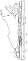
- Figure 1 is a general side view of a set of fasteners implementing the invention.
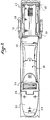
- Figure 2 is a partial top view of the assembly of Figure 1.
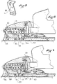
- FIG. 3 is a side view in section of the front fixing element of FIG. 1.
- FIG. 4 represents in top view and in two half-sections along different planes the fixing element of FIG. 3.
- Figure 5 is a view similar to Figure 1, in the presence of the shoe.
- Figure 6 shows in side view and in partial section the assembly of Figure 1 at the rear fixing element.
- FIG. 7 is a front view of a component of the fixing element shown in FIG. 3.
- Figure 8 is a view similar to Figure 1, and illustrates the mode of operation of the device.
- Figure 9 is a view similar to Figures 1 and 8 and illustrates another phase of operation of the device.
- Figure 10 shows an alternative embodiment of the device of the invention.
- FIG 11 shows schematically another alternative embodiment of the invention.
- FIG. 1 represents the middle part of a ski which is equipped with a set of fastening elements comprising a front retaining element and a rear retaining element, and an intermediate connection between the two elements.
- the front fixing element 1 represented in the embodiment of FIGS. 1 to 6 is essentially known from the French patent application published under the number FR 2 640 516.
- the base has a "U" shape open towards the rear, with two lateral branches 3a and 3b.
- the body is movable vertically relative to the base, for example by a deformable link, located in zone 9 at the junction between the body and the base.
- the body and the base are connected continuously by this deformable zone and form a one-piece element.
- the body has in its lower part a centering stud 2a, which is designed to be engaged between the two branches 3a and 3b of the base.
- the body 2 carries a jaw 4 for retaining the front end of the shoe.
- the jaw 4 comprises two lateral retaining wings 5 and 6, respectively articulated to the body 2 around axes 7 and 8.
- the jaw 4 also includes a sole clamp 12 for vertical retention of the shoe.
- the wings 5 and 6 are movable in response to the stresses of the shoe, against the restoring force applied to them by a spring 15.
- the spring 15 is housed in the body. It actuates a piston 16 also housed and guided in the body for a longitudinal translational movement.
- the figures show that the piston is housed and guided in a housing 17 of the body, and that the spring is engaged inside the piston. Its front end bears against the bottom of the piston, located on the front side of the fixing element.
- a screw 20, the head of which is retained at the front of the body moreover passes through the piston and the spring, and has a nut 21 towards the rear which retains the rear end of the spring. A rotation of the screw moves the rear end of the spring 15, which makes it possible to adjust the initial compression of the spring.
- the wings 5 and 6 have, beyond their axis of articulation to the body 7 and 8, a small arm 5a, 6a, which drives the piston 16 towards the rear, bearing against a shoulder 23 situated in the upper rear part of the piston 16.
- the fastening element 1 also comprises a support device for the front end of the shoe sole.
- the support device has a support plate 25 on which the shoe sole rests.
- the plate 25 can be equipped in its upper part with any suitable coating intended to facilitate lateral sliding of the shoe, for example a PTFE (polytetrafluoroethylene) plate. It has a width which is of the order of the width of the ski at this level.
- the plate 25 is articulated around a transverse axis 26, which is carried by a bearing secured to the base 3 or connected integrally to the ski.
- the element 1 shown in the embodiment of FIGS. 1 to 7 also has a compensation mechanism which alleviates the restoring force that the spring 15 exerts on the wings 5 and 6.
- This mechanism comprises a rocker 30 which is partly housed between the branches 3a and 3b of the base 3.
- the rocker is articulated around an axis 32 carried by these branches.
- the rocker 30 has an approximately horizontal wing 33 which is accessible on the rear of the fixing element between the branches 3a and 3b of the base.
- the front of the plate 25 is designed to be able to rest on the end of the branch 33.
- the rocker 30 also has an approximately vertical arm formed by two lateral pads which pass on each side of the piston 16, and which each carry on a shoulder 37 which the piston presents under the shoulder 23 of the wings. Only the shoe 35 is visible in FIGS. 4 and 5.
- a spring 38 recalls the plate 25 in a rest position which places its front end above the wing 33 of the rocker. When the shoe is engaged, the plate is lowered until it comes into contact with the branch 33. An automatic adaptation of the fastening element to the thickness of the shoe sole is thus achieved.
- the rocker has dimensions such that a vertical downward force exerted on its branch 33 is transmitted to the piston 16 in the form of a rearward stress, that is to say in the same direction as the stresses from the wings.
- the rearward movement of the piston 17 is accompanied by a rotation of the rocker 30 about the axis 32.
- the stress transmitted by the rocker to the piston 17 decreases the force as much as one of the wings must itself even exercise on the piston to move it enough back so that the opening of the wing allows the release of the wing.
- This mechanism compensates for the increase in friction between the shoe sole and the support plate 26 in the event of a front fall.
- a connecting rod 39 also connects the rocker, in front of the axis 32, to the upper part of the body.
- the body 2 rises by deformation of the zone 9. This movement is transmitted to the rocker by the link 39.
- This causes a stress on the piston which goes in the same direction as the previous stress. . This compensates for the increase in friction between the shoe and the sole clamp. If the stress on the sole is strong enough, the sole clamp lets the shoe sole escape upwards.
- the construction of the fixing element in itself is not limiting. It shows a mode of construction of the fastening element with which the present invention is compatible. Other constructions are suitable, in particular other simplified constructions.
- the assembly shown in FIG. 1 also has a rear retaining element 40.
- This element is of a known type. It has in particular a movable jaw 41 carried by a body 42. In a manner also known, the body 42 is movable along a slide 43.
- the fastening assembly also has a support plate 44 for the rear of the shoe sole which is located in front of the slide 43.
- the device according to the invention has a feeler capable of picking up stresses on the shoe.
- connection is intended to increase the restoring force that the spring opposes to the opening of a wing with the intensity of the stress picked up by the probe.
- the probe is the support plate 44 located at the front of the slide 43.
- the connection between the probe and the front element comprises a plate 46, the front end of which is connected to the front fixing element, and the rear end of which is movable.
- the rear end has a pallet 45 on which the shoe rests which arrives at the support plate 44 in the presence of the shoe.
- the plate 46 is in two parts assembled together, to be able to adapt the length of the plate to the spacing of the front and rear retaining elements.
- the slide is connected to the ski by a base plate 48 to which it is articulated around a transverse axis 49.
- the transverse axis is materialized by the cooperation of the rear end of the slide with the rear edge of the base plate.
- a hinge pin formed by a pin or any other suitable means may also be suitable.
- the connection between the slide and the base is provided to allow the front end of the slide to lower vertically, and to impede the roll movements between the slide and the base, so as to allow vertical suspension of the shoe while preserving good transmission of lateral forces, in particular when taking edges.
- the block 50 can be replaced by any suitable means, for example a spring.
- the slide can thus oscillate vertically downwards from the position defined by the stop 51, against the return force of the block 50.
- the slide can oscillate towards the bottom under the impulse of the solicitations of the shoe.
- the support plate 44 then forms a feeler which picks up the vertical stresses on the shoe, or more precisely the variations in the support force exerted by the rear end of the shoe sole.
- Figure 6 best illustrates the connection between the plate 46 and the slide 43.
- a rocker 52 articulated around a transverse axis 53 carried by the base 48.
- the rocker has a horizontal branch 55 engaged under the slide, and it further has a substantially vertical bearing face 56 against which comes a complementary face 57 located at the rear end of the plate, when the plate is in the low position.
- the plate 46 is preferably connected at the front by a hinge, and at its rear end, it is urged upwards by a device forming a ski brake 58.
- this device comprises two articulated arms 59 recalled by a spring 60.
- the front fastening element is itself mounted on a base plate 62 integrally connected to the ski.
- the base plate extends between the base and the ski. It is provided with a longitudinal housing inside which a slide 63 is guided.
- the slide opens out at the rear of the base plate and it is connected to the front of the plate 46 by articulation produced for example by the cooperation of complementary forms.
- connection is also ensured by a flexible tongue 64, each end of which is secured to the base plate and to the plate, respectively. Any other means of connection may also be suitable.
- the slide is in abutment against the lower end of a lever 66.
- This part enters the body 3 by a vertical recess 67 located on the front, its central part is crossed by the screw 20 and takes support under the screw head. Its upper end rests on the body beyond the screw.
- the lever 66 acts on the screw head like a lever, resting on the body 2. At rest, the screw head presses the lever 66 against the wall 68 of the recess 67.
- the device comprises a means which neutralizes the action of the slide on the spring in certain circumstances, in particular in certain cases of fall.
- a rear fall for example, each shoe of the skier exerts an upward force on the jaw of the front retaining element, and a downward force on the support plate which supports the heel of the shoe, that is to say here the support plate 44.
- an increase in the hardness of the spring is not desirable in these circumstances.
- the neutralization means is shown in the form of a toggle 69, which is integrated in the slide 63.
- the toggle 69 comprises two levers 70 and 71 connected together by a joint.
- the joint is located under an element of the body which moves vertically when the body lifts.
- this element is the centering stud 2a which passes through the base 3 of the retaining element.
- the stud 2a maintains the knee switch in the flattened position in a position close to the total extension, without however reaching this extension.
- the articulation of the two levers can move longitudinally under the stud with the displacement of the slide 63.
- a wedge or any other suitable means can be provided to prevent the levers of the toggle joint from reaching and exceeding a fully extended position.
- the toggle joint is capable of transmitting the longitudinal forces coming from the connecting plate 46. It is also capable of imposing on the entire slide the longitudinal movement which is imparted by the connecting plate 46. Given the fact that the toggle is close to the extension, the vertical reaction induced in the pad 20 is relatively weak.
- the kneepad tends to fold back.
- the lever 66 and the screw 20, if they had previously moved, are returned by the spring 15 to the rest position, that is to say the position where the lever 66 is in abutment against the wall 68.
- the longitudinal movement of the connecting plate 46 is then absorbed in the folding of the toggle joint, and the vertical forces of the shoe on the plate 44 are taken up by the block 50.
- the compensation mechanism of the retaining element is activated due to the elevation of the body.
- the rod 30 translates upward, causing with it the rotation of the rocker 30.
- the rocker exerts a thrust on the piston 16 which adds to the stresses coming from one or the other of the wings which is requested upon opening. The release of the shoe is thus facilitated.
- This operating phase of the retaining element is illustrated in FIG. 9.
- the body In the event that the stress is not sufficient to cause the release of the shoe, the body returns to its initial position when the stress ceases.
- the rocker 30 pivots towards its initial position, the stud 2a, by lowering, recalls the two levers of the toggle joint substantially in alignment with one another, the toggle joint is again ready to transmit the forces and the longitudinal movements of the connecting plate.
- the compensation mechanism for the fastening element is also active in the case of a front fall, that is to say a fall where the front of the shoe exerts a strong pressure on its support plate 25.
- the support plate 25 exerts on the rocker 30 a force which has the same effect on the compensation mechanism as a force due to a rear fall.
- the support plate 25 transmits the support force to the rocker 30 which in turn transmits it to the piston 16. The opening of the wings is facilitated in this case.
- the body of the retaining element does not rise due to the link with play between the rocker 30 and the link 39.
- the opening of the toggle joint 69 is not modified in this case.
- the folding amplitude of the toggle joint 69 can be modified by varying the position of the stud relative to the hinge zone 9 of the body, or else the length of the links.
- the stud as an element which controls the means for neutralizing the toggle joint is not limiting, and any other appropriate element could provide this control function, for example one of the branches of the rocker 30, or still the support plate 25 or an element controlled by this support plate.
- FIG. 10 illustrates an alternative embodiment of the invention.
- This figure shows a front retaining element 81, of the same type as the previous element, to which a connection plate 83 is connected.
- the rest of the fixing assembly is identical to what has been previously described.
- the front fixing element 81 is essentially identical to the element previously described. The difference lies in the means which connect the slide 86 and the front retaining element. The function of these means is here to slow down, or even block, the movement of the slide when its effect is not desired.
- the retaining element shown has a centering stud 87 provided with an opening 88 which the slide 86 passes right through.
- the slide has a reduced thickness.
- the centering stud has in its lower part a shoe 89 which delimits the lower part of the opening 88.
- Braking can also be achieved progressively by inserting a block of deformable material, for example an elastomer block, between the pad and the slide.
- a block of deformable material for example an elastomer block
- the effect of the displacement of the connecting plate on the spring is neutralized in certain circumstances, for example in the case of a fall backwards.
- the same result can be achieved in the case of a forward fall, or any other type of fall.
- the braking action of the slide can be coupled to a compensation effect, for example according to one of the modes described above.
- FIG. 11 illustrates another variant implementation of the invention.
- the support plate 90 on which the front of the shoe rests, or one end thereof, is held suspended by a spring 91 or any other suitable means, for example an elastomer block.
- a lock 92 slidably mounted in a vertical direction.
- the lock has a central housing which is traversed by the slide 93. This housing is delimited downwards by the upper surface of a shoe 95 for braking the slide.
- a spring 96 or any other suitable means resiliently recalls the latch upwards.
- the set has dimensions and characteristics such that in the absence of a stress raised downwards exerted by the shoe on its support plate, the latch 92 is recalled upwards by the spring 96. It slows any movement of the slide forward.
- the surfaces of the shoe and of the slide in contact can be coated with complementary toothing or any suitable means for achieving unidirectional braking, which blocks the movement of the slide forwards while allowing it to return to the rear.
- the slide can drive the lever 97 forward, under the impulse of a force exerted on the rear support plate and transmitted by the connection plate.
- the invention is not limited to the front fastening element which has been described. It applies to any other known construction of a front retaining element.
- the invention is also not limited to the case where the probe is associated with the rear fixing element.
- the probe that causes the longitudinal displacement of the slide could be located in another area of the shoe.
- the movement of the probe is not necessarily vertical.
- the feeler could also pick up the rolling stresses of the front or rear end of the shoe.
Landscapes
- Footwear And Its Accessory, Manufacturing Method And Apparatuses (AREA)
Applications Claiming Priority (2)
| Application Number | Priority Date | Filing Date | Title |
|---|---|---|---|
| FR9511640A FR2739301B1 (fr) | 1995-09-28 | 1995-09-28 | Element et ensemble de retenue d'une chaussure sur une planche de glisse |
| FR9511640 | 1995-09-28 |
Publications (1)
| Publication Number | Publication Date |
|---|---|
| EP0765680A1 true EP0765680A1 (de) | 1997-04-02 |
Family
ID=9483208
Family Applications (1)
| Application Number | Title | Priority Date | Filing Date |
|---|---|---|---|
| EP96112650A Withdrawn EP0765680A1 (de) | 1995-09-28 | 1996-08-06 | Element und Rückhaltevorrichtung für einen Snowboardschuh |
Country Status (3)
| Country | Link |
|---|---|
| EP (1) | EP0765680A1 (de) |
| JP (1) | JPH09117544A (de) |
| FR (1) | FR2739301B1 (de) |
Cited By (2)
| Publication number | Priority date | Publication date | Assignee | Title |
|---|---|---|---|---|
| FR2965187A1 (fr) * | 2010-09-28 | 2012-03-30 | Rossignol Sa | Dispositif de fixation de chaussure sur un ski avec interface de securite |
| EP2907556A1 (de) * | 2014-02-13 | 2015-08-19 | Tyrolia Technology GmbH | Vorderbacken einer Sicherheitsskibindung |
Citations (4)
| Publication number | Priority date | Publication date | Assignee | Title |
|---|---|---|---|---|
| FR2633994A1 (fr) * | 1988-07-08 | 1990-01-12 | Salomon Sa | Amortisseur hydraulique |
| WO1993014837A1 (fr) * | 1992-01-31 | 1993-08-05 | Salomon S.A. | Dispositif pour modifier la repartition d'un ski sur sa surface de glisse |
| FR2688144A1 (fr) * | 1991-10-10 | 1993-09-10 | Tyrolia Freizeitgeraete | Machoire avant pour fixation de chaussures de ski. |
| EP0674925A1 (de) * | 1994-03-30 | 1995-10-04 | Salomon S.A. | Skibindung |
-
1995
- 1995-09-28 FR FR9511640A patent/FR2739301B1/fr not_active Expired - Fee Related
-
1996
- 1996-08-06 EP EP96112650A patent/EP0765680A1/de not_active Withdrawn
- 1996-09-26 JP JP8254223A patent/JPH09117544A/ja active Pending
Patent Citations (4)
| Publication number | Priority date | Publication date | Assignee | Title |
|---|---|---|---|---|
| FR2633994A1 (fr) * | 1988-07-08 | 1990-01-12 | Salomon Sa | Amortisseur hydraulique |
| FR2688144A1 (fr) * | 1991-10-10 | 1993-09-10 | Tyrolia Freizeitgeraete | Machoire avant pour fixation de chaussures de ski. |
| WO1993014837A1 (fr) * | 1992-01-31 | 1993-08-05 | Salomon S.A. | Dispositif pour modifier la repartition d'un ski sur sa surface de glisse |
| EP0674925A1 (de) * | 1994-03-30 | 1995-10-04 | Salomon S.A. | Skibindung |
Cited By (4)
| Publication number | Priority date | Publication date | Assignee | Title |
|---|---|---|---|---|
| FR2965187A1 (fr) * | 2010-09-28 | 2012-03-30 | Rossignol Sa | Dispositif de fixation de chaussure sur un ski avec interface de securite |
| EP2438969A1 (de) * | 2010-09-28 | 2012-04-11 | Skis Rossignol | Skibindung mit Sicherheitsschnittstelle |
| US8585074B2 (en) | 2010-09-28 | 2013-11-19 | Skis Rossignol | Boot-attachment device on a ski with safety interface |
| EP2907556A1 (de) * | 2014-02-13 | 2015-08-19 | Tyrolia Technology GmbH | Vorderbacken einer Sicherheitsskibindung |
Also Published As
| Publication number | Publication date |
|---|---|
| FR2739301B1 (fr) | 1997-12-12 |
| FR2739301A1 (fr) | 1997-04-04 |
| JPH09117544A (ja) | 1997-05-06 |
Similar Documents
| Publication | Publication Date | Title |
|---|---|---|
| EP0556610B1 (de) | Vorrichtung zum Verändern der natürlichen Druckverteilung eines Skis auf seine Gleitfläche | |
| EP0530449B1 (de) | Vorrichtung zur Änderung der Druckverteilung eines Skis auf seiner Gleitfläche | |
| EP0624113B1 (de) | Vorrichtung zum verändern der natürlichen druckverteilung eines skis auf einer gleitfläche | |
| FR2471795A1 (fr) | Butee-avant de fixation de ski | |
| EP0617638B1 (de) | Einrichtung zur druckverteilung eines schis auf der gleitläche | |
| EP0674925B1 (de) | Skibindung | |
| EP0102868B1 (de) | Vorderbacken für eine Skisicherheitsbindung | |
| EP0692288B1 (de) | Bindung für Alpinski | |
| EP0653231B1 (de) | Bindungselement für Skier | |
| WO1996032992A1 (fr) | Fixation de securite pour le ski de telemark, la randonnee nordique et le saut a ski | |
| EP0658360A1 (de) | Vorrichtung zwischen Ski und Bindung | |
| EP0641233B1 (de) | Vorrichtung zum verändern der natürlichen druckverteilung eines skis auf seinegleitfläche | |
| EP0634196B1 (de) | Bindungselement für einen alphinen Ski | |
| CH660976A5 (fr) | Fixation de securite pour ski. | |
| EP0765680A1 (de) | Element und Rückhaltevorrichtung für einen Snowboardschuh | |
| CH673776A5 (de) | ||
| EP0667174B1 (de) | Sicherheitsbindung für Skier mit Ausgleichsvorrichtung | |
| EP0639393A1 (de) | Skibindungsteil | |
| EP0660740B1 (de) | Vorrichtung zum verteilen des drucks eines skis auf einer gleitenden fläche | |
| EP0627947B1 (de) | Sohlenplatte verbunden mit einem vorderbacken einer sicherheitsskibindung | |
| EP0495737B1 (de) | Skibremse | |
| EP0829278B1 (de) | Vorderbacken einer Sicherheitsgleitbrettbindung | |
| FR2582951A1 (fr) | Frein de ski | |
| FR2754727A1 (fr) | Butee avant de fixation de securite pour ski, a ajustage automatique de la durete de declenchement | |
| FR2657269A1 (fr) | Fixation de securite de ski alpin. |
Legal Events
| Date | Code | Title | Description |
|---|---|---|---|
| PUAI | Public reference made under article 153(3) epc to a published international application that has entered the european phase |
Free format text: ORIGINAL CODE: 0009012 |
|
| AK | Designated contracting states |
Kind code of ref document: A1 Designated state(s): AT CH DE IT LI |
|
| 17P | Request for examination filed |
Effective date: 19970917 |
|
| 17Q | First examination report despatched |
Effective date: 20000503 |
|
| STAA | Information on the status of an ep patent application or granted ep patent |
Free format text: STATUS: THE APPLICATION IS DEEMED TO BE WITHDRAWN |
|
| 18D | Application deemed to be withdrawn |
Effective date: 20000914 |