EP0765711A1 - Verfahren zur Herstellung einer hohlen Turbinenschaufel - Google Patents
Verfahren zur Herstellung einer hohlen Turbinenschaufel Download PDFInfo
- Publication number
- EP0765711A1 EP0765711A1 EP96402041A EP96402041A EP0765711A1 EP 0765711 A1 EP0765711 A1 EP 0765711A1 EP 96402041 A EP96402041 A EP 96402041A EP 96402041 A EP96402041 A EP 96402041A EP 0765711 A1 EP0765711 A1 EP 0765711A1
- Authority
- EP
- European Patent Office
- Prior art keywords
- blade
- manufacturing
- welded
- primary
- mask
- Prior art date
- Legal status (The legal status is an assumption and is not a legal conclusion. Google has not performed a legal analysis and makes no representation as to the accuracy of the status listed.)
- Granted
Links
- 238000004519 manufacturing process Methods 0.000 title claims description 34
- 238000009792 diffusion process Methods 0.000 claims abstract description 32
- 238000003754 machining Methods 0.000 claims abstract description 20
- 238000005520 cutting process Methods 0.000 claims abstract description 15
- 230000004888 barrier function Effects 0.000 claims abstract description 10
- 238000000151 deposition Methods 0.000 claims abstract description 7
- 239000000463 material Substances 0.000 claims abstract description 7
- 238000003466 welding Methods 0.000 claims abstract description 7
- 239000003351 stiffener Substances 0.000 claims description 26
- 238000000034 method Methods 0.000 claims description 18
- 239000000126 substance Substances 0.000 claims description 6
- 238000004140 cleaning Methods 0.000 claims description 5
- 239000011248 coating agent Substances 0.000 claims description 3
- 238000000576 coating method Methods 0.000 claims description 3
- 238000011960 computer-aided design Methods 0.000 claims description 3
- 238000005242 forging Methods 0.000 claims description 3
- 230000008021 deposition Effects 0.000 claims description 2
- 238000007789 sealing Methods 0.000 claims description 2
- 238000000926 separation method Methods 0.000 claims description 2
- 238000007493 shaping process Methods 0.000 claims 1
- 238000010137 moulding (plastic) Methods 0.000 abstract 1
- 238000009497 press forging Methods 0.000 abstract 1
- 230000003014 reinforcing effect Effects 0.000 abstract 1
- 229920000297 Rayon Polymers 0.000 description 14
- 239000002964 rayon Substances 0.000 description 14
- 206010040844 Skin exfoliation Diseases 0.000 description 10
- 230000015572 biosynthetic process Effects 0.000 description 7
- 230000008569 process Effects 0.000 description 7
- 239000000470 constituent Substances 0.000 description 5
- RTAQQCXQSZGOHL-UHFFFAOYSA-N Titanium Chemical compound [Ti] RTAQQCXQSZGOHL-UHFFFAOYSA-N 0.000 description 4
- 230000007547 defect Effects 0.000 description 4
- 210000004027 cell Anatomy 0.000 description 3
- 238000010276 construction Methods 0.000 description 3
- 241000920340 Pion Species 0.000 description 2
- 241001080024 Telles Species 0.000 description 2
- 239000010953 base metal Substances 0.000 description 2
- 230000015556 catabolic process Effects 0.000 description 2
- 230000006835 compression Effects 0.000 description 2
- 238000007906 compression Methods 0.000 description 2
- 238000006731 degradation reaction Methods 0.000 description 2
- 238000006073 displacement reaction Methods 0.000 description 2
- 238000007254 oxidation reaction Methods 0.000 description 2
- 229910001069 Ti alloy Inorganic materials 0.000 description 1
- 238000005452 bending Methods 0.000 description 1
- 239000011230 binding agent Substances 0.000 description 1
- 230000003749 cleanliness Effects 0.000 description 1
- 238000005056 compaction Methods 0.000 description 1
- 230000006866 deterioration Effects 0.000 description 1
- 238000001035 drying Methods 0.000 description 1
- 230000000694 effects Effects 0.000 description 1
- 238000010894 electron beam technology Methods 0.000 description 1
- 230000037406 food intake Effects 0.000 description 1
- 239000012535 impurity Substances 0.000 description 1
- 238000009434 installation Methods 0.000 description 1
- 238000005457 optimization Methods 0.000 description 1
- 230000003647 oxidation Effects 0.000 description 1
- 230000009467 reduction Effects 0.000 description 1
- 238000005507 spraying Methods 0.000 description 1
- 239000010936 titanium Substances 0.000 description 1
- 229910052719 titanium Inorganic materials 0.000 description 1
- 230000007704 transition Effects 0.000 description 1
Images



Classifications
-
- B—PERFORMING OPERATIONS; TRANSPORTING
- B21—MECHANICAL METAL-WORKING WITHOUT ESSENTIALLY REMOVING MATERIAL; PUNCHING METAL
- B21D—WORKING OR PROCESSING OF SHEET METAL OR METAL TUBES, RODS OR PROFILES WITHOUT ESSENTIALLY REMOVING MATERIAL; PUNCHING METAL
- B21D26/00—Shaping without cutting otherwise than using rigid devices or tools or yieldable or resilient pads, i.e. applying fluid pressure or magnetic forces
- B21D26/02—Shaping without cutting otherwise than using rigid devices or tools or yieldable or resilient pads, i.e. applying fluid pressure or magnetic forces by applying fluid pressure
- B21D26/053—Shaping without cutting otherwise than using rigid devices or tools or yieldable or resilient pads, i.e. applying fluid pressure or magnetic forces by applying fluid pressure characterised by the material of the blanks
- B21D26/055—Blanks having super-plastic properties
-
- B—PERFORMING OPERATIONS; TRANSPORTING
- B23—MACHINE TOOLS; METAL-WORKING NOT OTHERWISE PROVIDED FOR
- B23K—SOLDERING OR UNSOLDERING; WELDING; CLADDING OR PLATING BY SOLDERING OR WELDING; CUTTING BY APPLYING HEAT LOCALLY, e.g. FLAME CUTTING; WORKING BY LASER BEAM
- B23K20/00—Non-electric welding by applying impact or other pressure, with or without the application of heat, e.g. cladding or plating
- B23K20/02—Non-electric welding by applying impact or other pressure, with or without the application of heat, e.g. cladding or plating by means of a press ; Diffusion bonding
- B23K20/023—Thermo-compression bonding
-
- B—PERFORMING OPERATIONS; TRANSPORTING
- B23—MACHINE TOOLS; METAL-WORKING NOT OTHERWISE PROVIDED FOR
- B23K—SOLDERING OR UNSOLDERING; WELDING; CLADDING OR PLATING BY SOLDERING OR WELDING; CUTTING BY APPLYING HEAT LOCALLY, e.g. FLAME CUTTING; WORKING BY LASER BEAM
- B23K20/00—Non-electric welding by applying impact or other pressure, with or without the application of heat, e.g. cladding or plating
- B23K20/18—Zonal welding by interposing weld-preventing substances between zones not to be welded
-
- B—PERFORMING OPERATIONS; TRANSPORTING
- B23—MACHINE TOOLS; METAL-WORKING NOT OTHERWISE PROVIDED FOR
- B23P—METAL-WORKING NOT OTHERWISE PROVIDED FOR; COMBINED OPERATIONS; UNIVERSAL MACHINE TOOLS
- B23P15/00—Making specific metal objects by operations not covered by a single other subclass or a group in this subclass
- B23P15/04—Making specific metal objects by operations not covered by a single other subclass or a group in this subclass turbine or like blades from several pieces
-
- Y—GENERAL TAGGING OF NEW TECHNOLOGICAL DEVELOPMENTS; GENERAL TAGGING OF CROSS-SECTIONAL TECHNOLOGIES SPANNING OVER SEVERAL SECTIONS OF THE IPC; TECHNICAL SUBJECTS COVERED BY FORMER USPC CROSS-REFERENCE ART COLLECTIONS [XRACs] AND DIGESTS
- Y10—TECHNICAL SUBJECTS COVERED BY FORMER USPC
- Y10T—TECHNICAL SUBJECTS COVERED BY FORMER US CLASSIFICATION
- Y10T29/00—Metal working
- Y10T29/49—Method of mechanical manufacture
- Y10T29/49316—Impeller making
- Y10T29/49336—Blade making
-
- Y—GENERAL TAGGING OF NEW TECHNOLOGICAL DEVELOPMENTS; GENERAL TAGGING OF CROSS-SECTIONAL TECHNOLOGIES SPANNING OVER SEVERAL SECTIONS OF THE IPC; TECHNICAL SUBJECTS COVERED BY FORMER USPC CROSS-REFERENCE ART COLLECTIONS [XRACs] AND DIGESTS
- Y10—TECHNICAL SUBJECTS COVERED BY FORMER USPC
- Y10T—TECHNICAL SUBJECTS COVERED BY FORMER US CLASSIFICATION
- Y10T29/00—Metal working
- Y10T29/49—Method of mechanical manufacture
- Y10T29/49316—Impeller making
- Y10T29/49336—Blade making
- Y10T29/49339—Hollow blade
-
- Y—GENERAL TAGGING OF NEW TECHNOLOGICAL DEVELOPMENTS; GENERAL TAGGING OF CROSS-SECTIONAL TECHNOLOGIES SPANNING OVER SEVERAL SECTIONS OF THE IPC; TECHNICAL SUBJECTS COVERED BY FORMER USPC CROSS-REFERENCE ART COLLECTIONS [XRACs] AND DIGESTS
- Y10—TECHNICAL SUBJECTS COVERED BY FORMER USPC
- Y10T—TECHNICAL SUBJECTS COVERED BY FORMER US CLASSIFICATION
- Y10T29/00—Metal working
- Y10T29/49—Method of mechanical manufacture
- Y10T29/49826—Assembling or joining
- Y10T29/49895—Associating parts by use of aligning means [e.g., use of a drift pin or a "fixture"]
Definitions
- the present invention relates to a method for manufacturing a hollow turbine engine blade.
- the fan blade has a specific geometry linked to the small hub dimension which leads to having a very arched blade at the foot and a very flat profile at the top of the blade for a compression rate that is substantially constant over the height.
- the manufacturing process must allow the production of parts with evolving geometric parameters (variation in thickness of primary skins of the stiffener, variation in the forming angle of the stiffener, variation in the width of the welded zones, etc.).
- the manufactured part must indeed comply with the requirements of an optimized geometry having good resistance to vibration fatigue, good resistance to ingestion and fulfilling all the design conditions for the desired service life on the engine.
- the object of the invention is to provide the numerous known processes for the manufacture of hollow blades with substantial improvements or specificities aimed in particular at obtaining blades having mechanical characteristics under the conditions of use, thanks to an adequate geometry, particularly with regard to the realization of the dawn cavity.
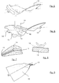
- a hollow blade 1 for a turbomachine, in particular a fan blade with a large cord intended for example for a turbofan engine is schematically represented in FIGS. 1 and 2.
- the blade 1 consists of a lower surface skin 2, an upper surface skin 3, these skins being separated to form an internal cavity 4 in the laqueile an element 5 forming multiple stiffeners 6 which provide the connection between the skins 2 and 3.
- said skins 2 and 3 are welded on their edges to form a leading edge 7 and a trailing edge 8 and the cavity 4 of the blade 1 has a radius 9 on the side of the leading edge and a radius 10 on the side of the trailing edge 8.
- the element 5 has welded areas, one on the lower surface 2 and the other on the upper surface 3 and thus the connections between the stiffeners 6 and the skins 2 and 3 form spokes such as 11 and 12, as shown on Figure 3.
- the first step (a) of the method, in accordance with the invention, of manufacturing a hollow blade such as 1 of a turbomachine fan comprises, from the drawing of the finished part, a study using means known per se of Computer Aided Design and Manufacturing or CAD / CAM.
- This study makes it possible to simulate a deflation of the upper surface skin 3 and the construction of the element 5 or central sheet so as to rest these two elements on the lower surface sheet or to place them at a known distance.
- the simulation software used makes it possible to specify the relative movement of the sheets during forming.
- each constituent element of the blade, respectively 2, 3 and 5, called the primary part receives extra thicknesses compatible with the forging process provided, as shown diagrammatically in FIG. 4.
- FIG. 5 shows the blanks 13 at the origin of these constituent elements 2, 3 and 5 of the blade with their machining allowance and which are obtained by forcing and stamping on a press.
- This improved process provides very precise geometry and product with improved mechanical characteristics, according to step (b) of the process.
- step (c) the raw parts 13 are machined, as shown in FIG. 6.
- the finishing of the internal surface of the primary parts is carried out by any machining process known per se.
- an excess thickness of material can be arranged on the primary skins around the entire periphery of the zone of these skins intended to form the blade cavity.
- This extra thickness portion 14 then constitutes a creep zone intended to be subsequently plastically deformed.
- a part 15 in excess thickness around the perimeter of the part is intended to ensure during assembly a spacing between the sheets.
- FIG. 7 shows a detail of these extra thicknesses 14 and 15.
- the cutting can thus be carried out using a wheel such as 21 having asymmetrical sides 22 and 23, on a machine with digital control.
- the determined shape of the wheel 21 and a judicious adjustment of the tool pressure ensure high precision cutting.
- This cutting operation can also be carried out by means of a scalpel controlled by an electro-pneumatic system so as to ensure a clean cut without creating damage to the primary part 13.
- low-power laser machining can be used for a clean cut without creating damage to the primary part 13.
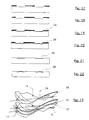
- Sub-step (d3) comprises the peeling of the non-welded zones 24, as shown diagrammatically in FIG. 12.
- Figure 24 shows schematically the completion of this assembly.
- the contour of the sandwich 30 obtained is closed, for example by means of a TIG arc weld 31, by electron beam or by laser.
- tubes 30 are welded and by means of these tubes 32, the vacuum is produced uniformly inside the sandwich 30 and is then maintained by sealing these tubes 32.
- the presence of the extra thickness 15 at the periphery of the pressure skins 28 and upper surface 27 allows a constant space to be provided between the component parts of the blade, during assembly.
- the sandwich 30 is welded by diffusion in an isostatic compression enclosure, so as to ensure intimate contact with the parts 13, 27 and 28 constituting the blade.
- FIGS. 25 and 26 show in one case the presence of positive flats 16 and lateral grooves 25 and in the other case of negative flats 33 and lateral grooves 25 on the primary parts in the zones intended for constitute the connections between stiffeners and skins as shown in the detail of the part in FIG. 3.
- the presence of the grooves 25 protects this limit of anti-diffusion product on the component parts of the blade by placing it at; below the level of the welding plane.
- the constituent parts of the blade 1 are formed under superplastic conditions by applying an inflation pressure in the internal cavity 4 so as to obtain, as shown diagrammatically in FIG. 2, the profile sought on the aerodynamic surfaces of the blade blade on the pressure side 2 and suction side 3 and the installation of stiffeners 6 from the central primary part 13.
- the sandwich 30 is placed in a mold 34 schematically represented in Figure 27.
- the mold 34 is in two parts 35 and 36 and its characteristics ensure precise relative positioning of the two parts 35 and 36, according to the six degrees of freedom.
- the mold 34 comprises in particular anti-rotation stops 37 whose position as well as the determined mold closing means make it possible to block the parts 35 and 36 in horizontal rotation and in translation, from the start of the forming cycle.
- the centering Vs 38 of the lower part 35 in line with the pins 17 and 18, at the ends of the part, ensure the adequate position of the latter in the mold 34. Thanks to this rigorous positioning of the blade blank in the mold 34 avoids any offset of the blade, in particular a lateral displacement which would have the effect of crushing the radii of cavity 9 and 10. These positioning characteristics of the mold and of the blade thus contribute to obtaining the dimensions and shapes of the departure radii of the vane cavity sought for the finished vane.
- a sub-step (f1) is carried out before inflation starts, comprising detachment of the primary cold parts which is required by the state of compaction of the anti-diffusion product.
- a predetermined forming pressurization cycle is then applied comprising in particular mechanical pressurization from the start of inflation, so as to ensure that there are no defects on the part obtained.
- a control is notably established between the clamping pressure of the mold and the inflation pressure.
- a sub-step (f2) occurs after the closure of the mold 34 during which a creep of the extra thickness 14 located around the area of formation of the blade cavity and previously mentioned is carried out.
- a controlled sequence of successive phases, creep then inflation simultaneously makes it possible to generate the internal geometry of the blade and to avoid skin defects at the start of cavities.
- the cycle defined for the application of the internal gas pressure may in particular respect a controlled deformation speed, so as to ensure the obtaining of cavity spokes, spokes in the connection zones between skins and stiffeners, the required radius surface condition as well as the absence of stiffening of the stiffener.
- FIG. 28 thus shows a detail of necking defect 39 on a stiffener which is avoided by the method according to the invention. Controlling the rate of deformation obtained thanks to the positioning characteristics of the mold and the application of the forming cycle ensures the desired value of the radii 9,10,11 and 12.
- the blade 1 is extracted from the mold 34 by mechanical means, including a constraint which maintains the geometry of the part during this operation which is carried out while maintaining the temperature forming.
Landscapes
- Engineering & Computer Science (AREA)
- Mechanical Engineering (AREA)
- Physics & Mathematics (AREA)
- Fluid Mechanics (AREA)
- Turbine Rotor Nozzle Sealing (AREA)
- Structures Of Non-Positive Displacement Pumps (AREA)
- Pressure Welding/Diffusion-Bonding (AREA)
- Forging (AREA)
Applications Claiming Priority (2)
| Application Number | Priority Date | Filing Date | Title |
|---|---|---|---|
| FR9511300 | 1995-09-27 | ||
| FR9511300A FR2739045B1 (fr) | 1995-09-27 | 1995-09-27 | Procede de fabrication d'une aube creuse de turbomachine |
Publications (2)
| Publication Number | Publication Date |
|---|---|
| EP0765711A1 true EP0765711A1 (de) | 1997-04-02 |
| EP0765711B1 EP0765711B1 (de) | 2000-01-05 |
Family
ID=9482942
Family Applications (1)
| Application Number | Title | Priority Date | Filing Date |
|---|---|---|---|
| EP96402041A Expired - Lifetime EP0765711B1 (de) | 1995-09-27 | 1996-09-26 | Verfahren zur Herstellung einer hohlen Turbinenschaufel |
Country Status (7)
| Country | Link |
|---|---|
| US (1) | US5826332A (de) |
| EP (1) | EP0765711B1 (de) |
| JP (1) | JP3281551B2 (de) |
| CA (1) | CA2186562C (de) |
| DE (1) | DE69605998T2 (de) |
| ES (1) | ES2140805T3 (de) |
| FR (1) | FR2739045B1 (de) |
Cited By (16)
| Publication number | Priority date | Publication date | Assignee | Title |
|---|---|---|---|---|
| RU2293020C2 (ru) * | 2001-02-01 | 2007-02-10 | Снекма Мотёр | Установка для формования детали и способ для его осуществления |
| EP2014387A1 (de) * | 2007-07-13 | 2009-01-14 | Rolls-Royce plc | Verfahren zum Herstellen einer Schaufel mit Dämpfungsfüller |
| EP2223766A1 (de) * | 2009-02-27 | 2010-09-01 | Rolls-Royce plc | Verfahren zur Herstellung einer Schaufel |
| EP2223767A1 (de) * | 2009-02-27 | 2010-09-01 | Rolls-Royce plc | Verfahren zur Herstellung einer Schaufel |
| EP2273069A3 (de) * | 2009-07-02 | 2011-10-12 | Rolls-Royce plc | Verfahren zum Bilden einer inneren Struktur in einer Hohlkomponente |
| US8241004B2 (en) | 2008-05-15 | 2012-08-14 | Rolls-Royce, Plc | Component structure |
| CN102862035A (zh) * | 2012-09-24 | 2013-01-09 | 西北工业大学 | 薄壁叶片分区域对称精密切削加工方法及其专用夹具 |
| US8365388B2 (en) | 2009-01-28 | 2013-02-05 | Rolls-Royce Plc | Method of joining plates of material to form a structure |
| CN103089323A (zh) * | 2011-10-31 | 2013-05-08 | 中航商用航空发动机有限责任公司 | 一种空心风扇叶片及其制造方法 |
| US8529720B2 (en) | 2008-07-24 | 2013-09-10 | Rolls-Royce, Plc | Aerofoil sub-assembly, an aerofoil and a method of making an aerofoil |
| US8701286B2 (en) | 2010-06-02 | 2014-04-22 | Rolls-Royce Plc | Rotationally balancing a rotating part |
| US8920893B2 (en) | 2009-01-27 | 2014-12-30 | Rolls-Royce Plc | Article with an internal structure |
| US8986490B2 (en) | 2010-11-26 | 2015-03-24 | Rolls-Royce Plc | Method of manufacturing a component |
| CN105773085A (zh) * | 2016-04-26 | 2016-07-20 | 杭州中水科技股份有限公司 | 一种扭曲叶片类工件的数控加工方法 |
| FR3032636A1 (fr) * | 2015-02-17 | 2016-08-19 | Inst De Rech Tech Jules Verne | Procede pour la fabrication d'une piece creuse raidie et vrillee de grande dimension et piece obtenue par un tel procede |
| CN106271447A (zh) * | 2016-08-31 | 2017-01-04 | 中国航天科技集团公司烽火机械厂 | 一种抖轮的制造方法 |
Families Citing this family (31)
| Publication number | Priority date | Publication date | Assignee | Title |
|---|---|---|---|---|
| FR2752388B1 (fr) * | 1996-08-14 | 1998-09-18 | Snecma | Procede de fabrication d'une aube creuse de turbomachine comportant un decollement apres soudage |
| FR2752539B1 (fr) | 1996-08-22 | 1998-09-18 | Snecma | Procede de fabrication d'une aube creuse de turbomachine et equipement de vrillage evolutif a chaud utilise |
| FR2754478B1 (fr) * | 1996-10-16 | 1998-11-20 | Snecma | Procede de fabrication d'une aube creuse de turbomachine |
| DE10145241C2 (de) * | 2001-09-13 | 2003-07-17 | Benteler Automobiltechnik Gmbh | Verfahren zur Herstellung von in der Dicke variierenden Blechprodukten |
| GB0203955D0 (en) | 2002-02-20 | 2002-04-03 | Rolls Royce Plc | A method of manufacturing an article by diffusion bonding and super[lastic forming |
| US6705011B1 (en) | 2003-02-10 | 2004-03-16 | United Technologies Corporation | Turbine element manufacture |
| FR2852537B1 (fr) * | 2003-03-21 | 2005-06-17 | Snecma Moteurs | Ensemble permettant la fabrication d'une piece mecanique creuse par soudage-diffusion et formage superplastique, utilisation d'un tel ensemble et procede de fabrication d'une telle piece mecanique |
| FR2853572B1 (fr) * | 2003-04-10 | 2005-05-27 | Snecma Moteurs | Procede de fabrication d'une piece mecanique creuse par soudage-diffusion et formage superplastique |
| DE102004001666A1 (de) * | 2004-01-12 | 2005-08-04 | Mtu Aero Engines Gmbh | Verfahren zur Herstellung von Hohlschaufeln |
| FR2871397B1 (fr) * | 2004-06-11 | 2006-09-22 | Snecma Moteurs Sa | Installation de conformation d'une aube creuse |
| FR2874339B1 (fr) * | 2004-08-23 | 2008-12-05 | Snecma Moteurs Sa | Procede de fabrication de pieces constitutives d'une aube creuse par forage sur presse |
| GB0522121D0 (en) * | 2005-10-29 | 2005-12-07 | Rolls Royce Plc | A blade |
| GB0614186D0 (en) * | 2006-07-18 | 2006-08-23 | Rolls Royce Plc | Blades |
| GB2450935B (en) * | 2007-07-13 | 2009-06-03 | Rolls Royce Plc | Component with internal damping |
| RU2412017C2 (ru) * | 2008-12-24 | 2011-02-20 | ОАО "Авиадвигатель" | Способ изготовления полой вентиляторной лопатки |
| GB0903613D0 (en) * | 2009-03-04 | 2009-04-08 | Rolls Royce Plc | Method of manufacturing an aerofoil |
| JP5205499B2 (ja) * | 2011-08-11 | 2013-06-05 | 橋田技研工業株式会社 | 蒸気タービン用静翼の製造法 |
| CN103089317B (zh) * | 2011-10-31 | 2015-06-10 | 中航商用航空发动机有限责任公司 | 一种空心风扇叶片及其制造方法 |
| US11000899B2 (en) | 2012-01-29 | 2021-05-11 | Raytheon Technologies Corporation | Hollow airfoil construction utilizing functionally graded materials |
| FR2994887B1 (fr) * | 2012-08-28 | 2016-04-15 | Snecma | Dispositif et procede pour la realisation de preformes |
| GB2510562B (en) | 2013-02-06 | 2015-02-25 | Rolls Royce Plc | Method of forming a bonded assembly |
| JP5858007B2 (ja) * | 2013-07-01 | 2016-02-10 | トヨタ自動車株式会社 | バルブシート用の肉盛方法及びシリンダヘッドの製造方法 |
| US9765623B2 (en) * | 2013-07-23 | 2017-09-19 | General Electric Company | Methods for modifying cooling holes with recess-shaped modifications |
| US9416667B2 (en) | 2013-11-22 | 2016-08-16 | General Electric Company | Modified turbine components with internally cooled supplemental elements and methods for making the same |
| CN104227103A (zh) * | 2014-07-24 | 2014-12-24 | 西安航空学院 | 薄壁件阶梯对称铣削加工方法 |
| RU2711697C1 (ru) * | 2019-04-15 | 2020-01-21 | Научно-производственная ассоциация "Технопарк Авиационных Технологий" | Способ изготовления упрочняющей накладки передней кромки лопатки вентилятора |
| CN113020476A (zh) * | 2021-03-05 | 2021-06-25 | 北京航空航天大学 | 一种空心叶片的塑性成形装置及方法 |
| CN113523728B (zh) * | 2021-08-04 | 2023-01-03 | 哈尔滨汽轮机厂有限责任公司 | 一种空心导叶片的特种加工方法 |
| CN114289595B (zh) * | 2021-12-21 | 2024-04-16 | 北京星航机电装备有限公司 | 一种半封闭舱体及其成形方法 |
| CN115921904B (zh) * | 2022-12-05 | 2026-04-17 | 国营川西机器厂 | 用于航空发动机铝合金叶片磨损的修复方法及加工工装 |
| CN119057394B (zh) * | 2024-09-04 | 2025-09-16 | 中国航空制造技术研究院 | 一种高刚性空心夹层结构及制造方法 |
Citations (7)
| Publication number | Priority date | Publication date | Assignee | Title |
|---|---|---|---|---|
| US4882823A (en) * | 1988-01-27 | 1989-11-28 | Ontario Technologies Corp. | Superplastic forming diffusion bonding process |
| EP0500458A1 (de) * | 1991-02-20 | 1992-08-26 | Societe Nationale D'etude Et De Construction De Moteurs D'aviation "Snecma" | Verfahren zur Herstellung einer hohlen Schauffel für eine Turbomaschine |
| GB2261032A (en) * | 1991-08-23 | 1993-05-05 | Mitsubishi Heavy Ind Ltd | Gas turbine blade with skin and core construction |
| EP0549172A1 (de) * | 1991-12-09 | 1993-06-30 | General Electric Company | Entwurf und Verfahren zur Herstellung von Hohlschaufeln (drei-Stücke Konzept) |
| US5269058A (en) * | 1992-12-16 | 1993-12-14 | General Electric Company | Design and processing method for manufacturing hollow airfoils |
| GB2269555A (en) * | 1992-08-14 | 1994-02-16 | Rolls Royce Plc | A method of manufacturing an article by superplastic forming and diffusion bonding |
| EP0700738A1 (de) * | 1994-09-07 | 1996-03-13 | Societe Nationale D'etude Et De Construction De Moteurs D'aviation "Snecma" | Verfahren zur Herstellung einer hohlen Turbinenschaufel |
Family Cites Families (4)
| Publication number | Priority date | Publication date | Assignee | Title |
|---|---|---|---|---|
| US5063662A (en) * | 1990-03-22 | 1991-11-12 | United Technologies Corporation | Method of forming a hollow blade |
| US5083371A (en) * | 1990-09-14 | 1992-01-28 | United Technologies Corporation | Hollow metal article fabrication |
| US5253419A (en) * | 1991-02-20 | 1993-10-19 | Societe Nationale D'etude Et De Construction De Moteurs D'aviation "S.N.E.C.M.A." | Method of manufacturing a hollow blade for a turboshaft engine |
| US5581882A (en) * | 1994-06-07 | 1996-12-10 | Rolls-Royce Plc | Method of manufacturing an article by superplastic forming and diffusion bonding |
-
1995
- 1995-09-27 FR FR9511300A patent/FR2739045B1/fr not_active Expired - Fee Related
-
1996
- 1996-09-26 CA CA002186562A patent/CA2186562C/fr not_active Expired - Fee Related
- 1996-09-26 EP EP96402041A patent/EP0765711B1/de not_active Expired - Lifetime
- 1996-09-26 DE DE69605998T patent/DE69605998T2/de not_active Expired - Lifetime
- 1996-09-26 US US08/721,352 patent/US5826332A/en not_active Expired - Lifetime
- 1996-09-26 ES ES96402041T patent/ES2140805T3/es not_active Expired - Lifetime
- 1996-09-27 JP JP25680996A patent/JP3281551B2/ja not_active Expired - Fee Related
Patent Citations (7)
| Publication number | Priority date | Publication date | Assignee | Title |
|---|---|---|---|---|
| US4882823A (en) * | 1988-01-27 | 1989-11-28 | Ontario Technologies Corp. | Superplastic forming diffusion bonding process |
| EP0500458A1 (de) * | 1991-02-20 | 1992-08-26 | Societe Nationale D'etude Et De Construction De Moteurs D'aviation "Snecma" | Verfahren zur Herstellung einer hohlen Schauffel für eine Turbomaschine |
| GB2261032A (en) * | 1991-08-23 | 1993-05-05 | Mitsubishi Heavy Ind Ltd | Gas turbine blade with skin and core construction |
| EP0549172A1 (de) * | 1991-12-09 | 1993-06-30 | General Electric Company | Entwurf und Verfahren zur Herstellung von Hohlschaufeln (drei-Stücke Konzept) |
| GB2269555A (en) * | 1992-08-14 | 1994-02-16 | Rolls Royce Plc | A method of manufacturing an article by superplastic forming and diffusion bonding |
| US5269058A (en) * | 1992-12-16 | 1993-12-14 | General Electric Company | Design and processing method for manufacturing hollow airfoils |
| EP0700738A1 (de) * | 1994-09-07 | 1996-03-13 | Societe Nationale D'etude Et De Construction De Moteurs D'aviation "Snecma" | Verfahren zur Herstellung einer hohlen Turbinenschaufel |
Cited By (25)
| Publication number | Priority date | Publication date | Assignee | Title |
|---|---|---|---|---|
| RU2293020C2 (ru) * | 2001-02-01 | 2007-02-10 | Снекма Мотёр | Установка для формования детали и способ для его осуществления |
| US8381398B2 (en) | 2007-07-13 | 2013-02-26 | Rolls-Royce Plc | Component with a damping filler and method |
| EP2014387A1 (de) * | 2007-07-13 | 2009-01-14 | Rolls-Royce plc | Verfahren zum Herstellen einer Schaufel mit Dämpfungsfüller |
| EP2014388A1 (de) * | 2007-07-13 | 2009-01-14 | Rolls-Royce plc | Schaufel für Turbomaschine mit Dämpfungsfüller sowie Verfahren zu ihrer Herstellung |
| EP2014386A1 (de) | 2007-07-13 | 2009-01-14 | Rolls-Royce plc | Komponente mit Dämpfungsfüller |
| US8857054B2 (en) | 2007-07-13 | 2014-10-14 | Rolls-Royce Plc | Method of forming an aerofoil with a damping filler |
| US8182233B2 (en) | 2007-07-13 | 2012-05-22 | Rolls-Royce Plc | Component with a damping filler |
| US8241004B2 (en) | 2008-05-15 | 2012-08-14 | Rolls-Royce, Plc | Component structure |
| US8529720B2 (en) | 2008-07-24 | 2013-09-10 | Rolls-Royce, Plc | Aerofoil sub-assembly, an aerofoil and a method of making an aerofoil |
| US8920893B2 (en) | 2009-01-27 | 2014-12-30 | Rolls-Royce Plc | Article with an internal structure |
| US8365388B2 (en) | 2009-01-28 | 2013-02-05 | Rolls-Royce Plc | Method of joining plates of material to form a structure |
| EP2223766A1 (de) * | 2009-02-27 | 2010-09-01 | Rolls-Royce plc | Verfahren zur Herstellung einer Schaufel |
| US8382441B2 (en) | 2009-02-27 | 2013-02-26 | Rolls-Royce Plc | Method of manufacturing a blade |
| US8555501B2 (en) | 2009-02-27 | 2013-10-15 | Rolls-Royce Plc | Method of manufacturing a blade |
| EP2223767A1 (de) * | 2009-02-27 | 2010-09-01 | Rolls-Royce plc | Verfahren zur Herstellung einer Schaufel |
| EP2273069A3 (de) * | 2009-07-02 | 2011-10-12 | Rolls-Royce plc | Verfahren zum Bilden einer inneren Struktur in einer Hohlkomponente |
| US8701286B2 (en) | 2010-06-02 | 2014-04-22 | Rolls-Royce Plc | Rotationally balancing a rotating part |
| US8986490B2 (en) | 2010-11-26 | 2015-03-24 | Rolls-Royce Plc | Method of manufacturing a component |
| CN103089323A (zh) * | 2011-10-31 | 2013-05-08 | 中航商用航空发动机有限责任公司 | 一种空心风扇叶片及其制造方法 |
| CN103089323B (zh) * | 2011-10-31 | 2015-01-14 | 中航商用航空发动机有限责任公司 | 一种空心风扇叶片及其制造方法 |
| CN102862035B (zh) * | 2012-09-24 | 2015-01-28 | 西北工业大学 | 薄壁叶片分区域对称精密切削加工方法及其专用夹具 |
| CN102862035A (zh) * | 2012-09-24 | 2013-01-09 | 西北工业大学 | 薄壁叶片分区域对称精密切削加工方法及其专用夹具 |
| FR3032636A1 (fr) * | 2015-02-17 | 2016-08-19 | Inst De Rech Tech Jules Verne | Procede pour la fabrication d'une piece creuse raidie et vrillee de grande dimension et piece obtenue par un tel procede |
| CN105773085A (zh) * | 2016-04-26 | 2016-07-20 | 杭州中水科技股份有限公司 | 一种扭曲叶片类工件的数控加工方法 |
| CN106271447A (zh) * | 2016-08-31 | 2017-01-04 | 中国航天科技集团公司烽火机械厂 | 一种抖轮的制造方法 |
Also Published As
| Publication number | Publication date |
|---|---|
| CA2186562C (fr) | 2004-05-25 |
| US5826332A (en) | 1998-10-27 |
| ES2140805T3 (es) | 2000-03-01 |
| CA2186562A1 (fr) | 1997-03-28 |
| FR2739045B1 (fr) | 1997-10-31 |
| EP0765711B1 (de) | 2000-01-05 |
| DE69605998D1 (de) | 2000-02-10 |
| FR2739045A1 (fr) | 1997-03-28 |
| JPH09125903A (ja) | 1997-05-13 |
| JP3281551B2 (ja) | 2002-05-13 |
| DE69605998T2 (de) | 2000-06-29 |
Similar Documents
| Publication | Publication Date | Title |
|---|---|---|
| EP0765711B1 (de) | Verfahren zur Herstellung einer hohlen Turbinenschaufel | |
| EP1695789B1 (de) | Verfahren zur Reparatur einer integral beschaufelten Rotorscheibe, Prüfling für den Anfang und das Ende des Verfahrens | |
| JP4267856B2 (ja) | 溝付きブリスクおよびそれを作る方法 | |
| CA2509803C (fr) | Procede de reparation d'un element d'aube | |
| EP1574270B1 (de) | Verfahren zur herstellung einer verstärkungs-anstrom oder hinterkante für eine gebläseschaufel | |
| EP0303535B1 (de) | Herstellungsverfahren von Kompressor- oder Turbinenstatorstufen, so hergestellte Schaufeln und Schaufelgitter | |
| CA2823497C (fr) | Procede de realisation d'un renfort metallique | |
| CA2823525C (fr) | Procede de realisation d'un renfort metallique | |
| CA2870229C (fr) | Procede de realisation d'un renfort metallique avec insert pour la protection d'un bord d'attaque en materiau composite | |
| EP0500458B1 (de) | Verfahren zur Herstellung einer hohlen Schauffel für eine Turbomaschine | |
| FR2695163A1 (fr) | Aube creuse pour turbomachine et son procédé de fabrication. | |
| EP2735706B1 (de) | Gleichrichter mit Laufradschaufeln eines Kompressors eines axialen Turbotriebwerks, und Herstellungsverfahren | |
| FR3046557A1 (fr) | Procede de fabrication d'un bouclier de bord d'attaque comprenant une etape de fabrication additive et bouclier de bord d'attaque | |
| CA2514106C (fr) | Procede de fabrication de pieces constitutives d'une aube creuse par laminage | |
| FR2631268A1 (fr) | Procede de reparation d'aubes pour disques ailetes de rotor de turbomachine et roue a aubes de rotor obtenue par ledit procede | |
| FR2739832A1 (fr) | Structure metallique creuse monobloc et dissymetrique telle qu'un bord de fuite d'un bec d'attaque d'une voilure d'aeronef et son procede de fabrication | |
| EP3898073A1 (de) | Verfahren zur herstellung einer metallverstärkung für eine turbomaschinenschaufel | |
| EP1721698A1 (de) | Herstellungsverfahren für eine Hohlschaufel mit Schaufelspitze und Reparaturverfahren für eine solche Schaufel | |
| EP1481755B1 (de) | Verfahren zur Herstellung einer hohlen Schaufel für Strömungsmaschine | |
| WO2013088078A1 (fr) | Secteur de redresseur pour un compresseur de turbomachine réalisé par brasage d'une plate-forme de ses aubes sur une virole | |
| FR2514072A1 (fr) | Procede de fabrication d'une aube pour moteur a turbine a gaz |
Legal Events
| Date | Code | Title | Description |
|---|---|---|---|
| PUAI | Public reference made under article 153(3) epc to a published international application that has entered the european phase |
Free format text: ORIGINAL CODE: 0009012 |
|
| 17P | Request for examination filed |
Effective date: 19961007 |
|
| AK | Designated contracting states |
Kind code of ref document: A1 Designated state(s): BE CH DE ES FR GB IT LI SE |
|
| GRAG | Despatch of communication of intention to grant |
Free format text: ORIGINAL CODE: EPIDOS AGRA |
|
| GRAG | Despatch of communication of intention to grant |
Free format text: ORIGINAL CODE: EPIDOS AGRA |
|
| GRAH | Despatch of communication of intention to grant a patent |
Free format text: ORIGINAL CODE: EPIDOS IGRA |
|
| 17Q | First examination report despatched |
Effective date: 19990615 |
|
| GRAH | Despatch of communication of intention to grant a patent |
Free format text: ORIGINAL CODE: EPIDOS IGRA |
|
| GRAA | (expected) grant |
Free format text: ORIGINAL CODE: 0009210 |
|
| ITF | It: translation for a ep patent filed | ||
| AK | Designated contracting states |
Kind code of ref document: B1 Designated state(s): BE CH DE ES FR GB IT LI SE |
|
| REG | Reference to a national code |
Ref country code: CH Ref legal event code: NV Representative=s name: MICHELI & CIE INGENIEURS-CONSEILS Ref country code: CH Ref legal event code: EP |
|
| REF | Corresponds to: |
Ref document number: 69605998 Country of ref document: DE Date of ref document: 20000210 |
|
| GBT | Gb: translation of ep patent filed (gb section 77(6)(a)/1977) |
Effective date: 20000125 |
|
| REG | Reference to a national code |
Ref country code: ES Ref legal event code: FG2A Ref document number: 2140805 Country of ref document: ES Kind code of ref document: T3 |
|
| PLBE | No opposition filed within time limit |
Free format text: ORIGINAL CODE: 0009261 |
|
| STAA | Information on the status of an ep patent application or granted ep patent |
Free format text: STATUS: NO OPPOSITION FILED WITHIN TIME LIMIT |
|
| 26N | No opposition filed | ||
| REG | Reference to a national code |
Ref country code: GB Ref legal event code: IF02 |
|
| REG | Reference to a national code |
Ref country code: FR Ref legal event code: TP Ref country code: FR Ref legal event code: CD |
|
| REG | Reference to a national code |
Ref country code: ES Ref legal event code: PC2A |
|
| REG | Reference to a national code |
Ref country code: CH Ref legal event code: PUE Owner name: DASSAULT AVIATION Free format text: DASSAULT AVIATION#9, ROND POINT DES CHAMPS ELYSEES, MARCEL DASSAULT#F-75008 PARIS (FR) $ SOCIETE NATIONALE D'ETUDE ET DE CONSTRUCTION DE MOTEURS D'AVIATION, "S.N.E.C.M.A."#2, BOULEVARD DU GENERAL MARTIAL VALIN#75015 PARIS (FR) -TRANSFER TO- DASSAULT AVIATION#9, ROND POINT DES CHAMPS ELYSEES, MARCEL DASSAULT#F-75008 PARIS (FR) $ LEXVALL#2, BOULEVARD DU GENERAL MARTIAL VALIN#75015 PARIS (FR) Ref country code: CH Ref legal event code: PFA Owner name: DASSAULT AVIATION Free format text: DASSAULT AVIATION#9, ROND POINT DES CHAMPS ELYSEES, MARCEL DASSAULT#F-75008 PARIS (FR) $ LEXVALL#2, BOULEVARD DU GENERAL MARTIAL VALIN#75015 PARIS (FR) -TRANSFER TO- DASSAULT AVIATION#9, ROND POINT DES CHAMPS ELYSEES, MARCEL DASSAULT#F-75008 PARIS (FR) $ SNECMA MOTEURS#2, BOULEVARD DU GENERAL MARTIAL VALIN#75015 PARIS (FR) |
|
| REG | Reference to a national code |
Ref country code: FR Ref legal event code: CD |
|
| REG | Reference to a national code |
Ref country code: CH Ref legal event code: PFA Owner name: DASSAULT AVIATION Free format text: DASSAULT AVIATION#9, ROND POINT DES CHAMPS ELYSEES, MARCEL DASSAULT#F-75008 PARIS (FR) $ SNECMA MOTEURS#2, BOULEVARD DU GENERAL MARTIAL VALIN#75015 PARIS (FR) -TRANSFER TO- DASSAULT AVIATION#9, ROND POINT DES CHAMPS ELYSEES, MARCEL DASSAULT#F-75008 PARIS (FR) $ SNECMA#2, BOULEVARD DU GENERAL MARTIAL VALIN#75015 PARIS (FR) |
|
| REG | Reference to a national code |
Ref country code: ES Ref legal event code: PC2A |
|
| REG | Reference to a national code |
Ref country code: GB Ref legal event code: 732E Free format text: REGISTERED BETWEEN 20120927 AND 20121003 |
|
| PGFP | Annual fee paid to national office [announced via postgrant information from national office to epo] |
Ref country code: CH Payment date: 20140826 Year of fee payment: 19 Ref country code: DE Payment date: 20140822 Year of fee payment: 19 |
|
| PGFP | Annual fee paid to national office [announced via postgrant information from national office to epo] |
Ref country code: GB Payment date: 20140822 Year of fee payment: 19 Ref country code: SE Payment date: 20140826 Year of fee payment: 19 Ref country code: ES Payment date: 20140910 Year of fee payment: 19 |
|
| PGFP | Annual fee paid to national office [announced via postgrant information from national office to epo] |
Ref country code: IT Payment date: 20140826 Year of fee payment: 19 |
|
| PGFP | Annual fee paid to national office [announced via postgrant information from national office to epo] |
Ref country code: BE Payment date: 20140825 Year of fee payment: 19 Ref country code: FR Payment date: 20140905 Year of fee payment: 19 |
|
| REG | Reference to a national code |
Ref country code: DE Ref legal event code: R119 Ref document number: 69605998 Country of ref document: DE |
|
| PG25 | Lapsed in a contracting state [announced via postgrant information from national office to epo] |
Ref country code: IT Free format text: LAPSE BECAUSE OF NON-PAYMENT OF DUE FEES Effective date: 20150926 |
|
| REG | Reference to a national code |
Ref country code: CH Ref legal event code: PL |
|
| REG | Reference to a national code |
Ref country code: SE Ref legal event code: EUG |
|
| GBPC | Gb: european patent ceased through non-payment of renewal fee |
Effective date: 20150926 |
|
| PG25 | Lapsed in a contracting state [announced via postgrant information from national office to epo] |
Ref country code: SE Free format text: LAPSE BECAUSE OF NON-PAYMENT OF DUE FEES Effective date: 20150927 |
|
| REG | Reference to a national code |
Ref country code: FR Ref legal event code: ST Effective date: 20160531 |
|
| PG25 | Lapsed in a contracting state [announced via postgrant information from national office to epo] |
Ref country code: GB Free format text: LAPSE BECAUSE OF NON-PAYMENT OF DUE FEES Effective date: 20150926 Ref country code: LI Free format text: LAPSE BECAUSE OF NON-PAYMENT OF DUE FEES Effective date: 20150930 Ref country code: DE Free format text: LAPSE BECAUSE OF NON-PAYMENT OF DUE FEES Effective date: 20160401 Ref country code: CH Free format text: LAPSE BECAUSE OF NON-PAYMENT OF DUE FEES Effective date: 20150930 |
|
| PG25 | Lapsed in a contracting state [announced via postgrant information from national office to epo] |
Ref country code: FR Free format text: LAPSE BECAUSE OF NON-PAYMENT OF DUE FEES Effective date: 20150930 |
|
| REG | Reference to a national code |
Ref country code: ES Ref legal event code: FD2A Effective date: 20161026 |
|
| PG25 | Lapsed in a contracting state [announced via postgrant information from national office to epo] |
Ref country code: ES Free format text: LAPSE BECAUSE OF NON-PAYMENT OF DUE FEES Effective date: 20150927 |
|
| PG25 | Lapsed in a contracting state [announced via postgrant information from national office to epo] |
Ref country code: BE Free format text: LAPSE BECAUSE OF NON-PAYMENT OF DUE FEES Effective date: 20150930 |