EP0765836A2 - Dispositif de positionnement pour ascenseur - Google Patents
Dispositif de positionnement pour ascenseur Download PDFInfo
- Publication number
- EP0765836A2 EP0765836A2 EP96307153A EP96307153A EP0765836A2 EP 0765836 A2 EP0765836 A2 EP 0765836A2 EP 96307153 A EP96307153 A EP 96307153A EP 96307153 A EP96307153 A EP 96307153A EP 0765836 A2 EP0765836 A2 EP 0765836A2
- Authority
- EP
- European Patent Office
- Prior art keywords
- elevator
- group
- position apparatus
- sensor modules
- sensor
- Prior art date
- Legal status (The legal status is an assumption and is not a legal conclusion. Google has not performed a legal analysis and makes no representation as to the accuracy of the status listed.)
- Withdrawn
Links
Images


Classifications
-
- B—PERFORMING OPERATIONS; TRANSPORTING
- B66—HOISTING; LIFTING; HAULING
- B66B—ELEVATORS; ESCALATORS OR MOVING WALKWAYS
- B66B1/00—Control systems of elevators in general
- B66B1/34—Details, e.g. call counting devices, data transmission from car to control system, devices giving information to the control system
- B66B1/3492—Position or motion detectors or driving means for the detector
Definitions
- the present invention relates generally to elevators and, in particular, relates to elevator position detection.
- an elevator system To stop an elevator smoothly and level with a sill, an elevator system must know when to initiate a stop, when to go into a leveling mode of operation, and when to begin opening the landing doors.
- the elevator system initiates a leveling mode of operation when the car reaches a leveling zone in the hoistway. Most elevators begin opening the landing doors two to three inches (50-75 mm) before the elevator platform is actually level with the sill to speed-up passenger transfer. This zone is known as a door zone. To perform these functions accurately, it is necessary to know the exact location of the car at all times. As a consequence, elevator position devices are used to monitor elevator car position.
- One existing elevator position device includes steel bars, vanes or magnets attached to a floating steel tape, running the length of the hoistway, and a hoistway position reader box mounted on the car.
- the steel bars, vanes or magnets are located on the steel tape with respect to their corresponding landing sills to mark the door zone position and the approximate distance from the door zone for deceleration.
- the reader box contains a fixed number of sensors that sense the location of each steel bar, vane or magnet as the car travels up and down the hoistway such that the elevator system may determine, among other things, if the elevator car is within the door zone corresponding to a particular landing.
- the sensors In response to detecting the steel bars, vanes or magnets, the sensors transmit signals to a shared printed circuit board ("PCB") so that the signals can be processed and transmitted to an elevator controller.
- PCBs are designed for a fixed number of signals.
- the existing floating tape devices have a shared and fixed configuration to interface with the elevator controller.
- Elevator systems have a variety of sensor configurations that are dependent upon the particular elevator system's requirements and its associated costs.
- the existing floating tape devices are not interchangeable between many elevator systems without significant modification of the PCB and/or the reader box. Additionally, if the elevator system is upgraded ("modernized") such that additional features are required for the position detection device, the PCB and/or the reader box must be modified or replaced.
- the group of sensor modules correspond to an elevator system of the plurality of elevator systems such that the group of sensor modules provide sensor signals to the elevator system in response to said encoded medium.
- the group of apertures have a subgroup of apertures for receiving the group of sensor modules corresponding to the elevator system.
- the group of apertures is configured for receiving other groups of sensor modules such that the elevator position apparatus is configured for each of the plurality of elevator systems.
- an elevator system 10 employing a preferred embodiment of an elevator position apparatus 11 is shown.
- An elevator car 12 is disposed in a hoistway 14 such that the elevator car 12 may travel along elevator guide rails 16 disposed vertically in the hoistway 14.
- a door operator 18 is disposed on the elevator car 12 so that the door operator 18 may open and close the elevator door(s) 20 as needed.
- An elevator controller 22 is disposed in a machine room 24 which monitors and provides system control of the elevator system 10.
- a traveling cable 26 is used to provide an electrical connection between the elevator controller 22 and electrical equipment in the hoistway 14.
- the present invention can be used in conjunction with other elevator systems including hydraulic and linear motor systems, among others.
- the elevator position apparatus 11 is used in conjunction with the elevator system 10 to accurately determine the position of the elevator car 12 within the hoistway 14.
- the elevator position apparatus 11 includes an encoded medium 28, a group of sensor modules 31, and a universal reader 44.
- a preferred embodiment of the encoded medium 28 is shown that includes a steel tape 29, having outer edges 30, disposed vertically in the hoistway 14.
- the steel tape 29 is attached to upper and lower horizontal supports 32, 34 by upper and lower tape hitches 36, 38 respectively.
- the upper and lower supports 32, 34 provide vertical support to the steel tape 29 and are attached to the guide rails 16.
- a spring 40 is used in conjunction with the lower hitch 38 for providing tension in the steel tape 29.
- the encoded medium 28 may be encoded using various methods. For example, optical or mechanical encoding methods can be used.
- the encoded medium 28 is encoded by disposing magnets 42 on the steel tape 29 in predetermined positions.
- magnets 42 are located on the steel tape 29 with respect to their corresponding hoistway landings (not shown) to mark the appropriate door zone.
- the steel tape 29 includes one to three discrete vertical planes ("traces") 46 for placing magnets 42. Each magnet 42 is positioned along one of the traces 46 in the steel tape 29.
- traces discrete vertical planes
- sensor modules 31 are used to detect the encoding embodied in the encoded medium 28.
- the sensor modules 31 are hall effect devices which produce electrical sensor signals when placed in close proximity to the magnets 42.
- Each sensor module 31 of the present invention includes a hall sensor 48, voltage stabilization circuitry 50 and power circuitry 52.
- the hall sensor 48 provides a sensor signal in response to sensing the magnets 42.
- the voltage stabilization circuitry 50 stabilizes an unregulated voltage provided by either the controller 22 or a battery (not shown) and provides the stabilized voltage to the hall sensor 48.
- the power circuitry 52 provides amplification to the sensor signal so that the sensor signal can activate a relay or a lamp located in the controller 22 or the machine room 24. Thus, the sensor signal can be directly transmitted from the sensor module 31 to the machine room 24 without further modification. Suitable designs for the voltage stabilization circuitry 50 and the power circuitry 52 are known to those skilled in the art.
- the sensor modules 31 eliminate the need for a separate PCB because each individual sensor module 31 provides voltage regulation and sensor signal amplification functions previously provided by the PCB.
- the sensor modules 31 provide the advantage of improved fault isolation and facilitate replacement of faulty equipment because only faulty sensor modules need to be replaced in the event of a sensor failure; as opposed to additionally testing and replacing the PCB. It also provides the advantage of adaptability as is explained hereinbelow.
- the sensor modules 31 are disposed in the universal reader 44 as is also described hereinbelow.
- the universal reader 44 as shown in Figs. 2, 3, is attached to an angle bracket 54 which is attached to mounting channels 56 which in turn are attached to the crosshead 58 of the elevator car 12. As a result, the universal reader 44 moves with the elevator car 12 as the elevator car 12 moves up and down the hoistway 14. The universal reader 44 moves the sensor modules 31 along the encoded medium 28 as the elevator car 12 travels in the hoistway 14.
- the universal reader 44 includes guides 60 and a channel 62 having a mounting plate 63 and two supports 65 extending at ninety degrees from the mounting plate 63.
- the mounting plate 63 has a group of apertures 64 for receiving the sensor modules 31.
- four guides 60 are attached to the channel 62 for facilitating movement of the universal reader 44 along the encoded medium 28.
- Each guide 60 has a longitudinal groove 66 defining an area formed therein such that the groove 66 is adapted to receive and retain the outer edges 30 of the steel tape 29.
- the universal reader 44 travels in the same direction with the outer edges 30 of the steel tape 29 traversing through the grooves 66 formed in the guides 60.
- a constant distance between the sensor modules 31 and the steel tape 29 is maintained as the universal reader 44 travels in the hoistway 14.
- the group of apertures 64 is configured for receiving various groups of sensor modules 31 such that the elevator position apparatus 11 may be used with a plurality of elevator systems.
- the channel 62 is interchangeable within any of the plurality of elevator systems without modification.
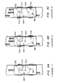
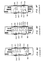
- the channel 62 facilitates placement of sensor modules 31 in different elevator systems by including a group of apertures 64 having subgroups of apertures 68 (shown in Fig. 9) corresponding to each group of sensor modules 31 in each of the plurality of elevator systems.
- the sensor modules 31 are disposed in the apertures such that the sensor modules 31 face the steel tape 29 and are affixed to the channel 62 in a conventional manner by use of a known fastening means such as a threaded nut 70.
- the sensor modules 31 are disposed in the same trace 46 as their corresponding magnets 42 so that the sensor modules 31 detect the location of their corresponding magnets 42 as the elevator car 12 and the universal reader 44 travel in the hoistway 14.
- a large variety of sensor module arrangements may be used as is described below.
- the sensor module arrangements corresponding to the plurality of elevator systems include six versions according to a preferred embodiment of the present invention.
- Each sensor module arrangement corresponds to one subgroup 68 of the group 64 of sensor modules 31.
- a low cost elevator system may only require two leveling sensors modules 1LV, 2LV, one door zone sensor module DZI and one performance monitoring sensor module SAC.
- the elevator system of version 1 only requires two traces 46 for the placement of two magnets 42 corresponding to the sensor modules 1LV, 2LV, DZI, SAC; one magnet corresponds to the two leveling sensors 1LV, 2LV and the door zone magnet DZI disposed at each landing and the other magnet corresponds to the performance monitoring sensor SAC disposed at a main floor.
- Version 2 illustrates an elevator system that further includes limit switch sensor modules 1LS, 2LS for determining the top and bottom terminal positions.
- the ability to determine the top and bottom terminals is useful, for example, in elevator systems which perform correction runs after a power failure.
- the elevator position apparatus 11 embodying the principles of the present invention is easily and inexpensively modified to version 2 by simply installing the 1LV, 2LV, DZI 1LS, 2LS and SAC sensor modules into the universal reader 44 and properly placing magnets 42 on the steel tape 29 without the need for further modification.
- Version 3 illustrates a similar elevator system with a larger distance between the leveling sensor modules 1LV, 2LV to provide additional information derived from measurements of level signals produced by the sensor modules 1LV, 2LV.
- Version 4 further includes releveling sensors UIS, DIS for providing a more advanced leveling performance.
- Version 5 further includes a deceleration down sensor module IPD, a deceleration up sensor module IPU, and a delayed releveling sensor module DIS1.
- the deceleration up and down sensor modules IPU, IPD are required by elevator systems that are not able to derive the position at which to begin a deceleration for stopping at a landing (i.e., an elevator system without a speed encoder).
- the delayed releveling sensor module DIS1 provides additional information for advanced leveling functions that are required by some elevator systems. For example, hydraulic elevators have different leveling requirements at the bottom terminal and thus require a delayed releveling sensor DIS1.
- Version 6 illustrates a sensor module configuration similar to version 5 with the exception of not including releveling functions and including a different distance between the leveling sensors 1LV, 2LV.
- the present invention allows the number of sensor modules 31 to be optimized to each elevator system without altering the physical components of the universal reader 44.
- the only physical change required to adapt the elevator position apparatus of the present invention from one elevator system to another with different sensor requirements consists of adding or subtracting a given number of sensor modules 31 and their associated magnets 42. Therefore, the elevator position apparatus 11 of the present invention provides a significant cost reduction in terms of both physical components and the amount of time spent on installing or modifying the elevator position apparatus.
- each sensor module 31 includes the electrical components required to directly transmit signals between the sensor modules 31 and the elevator controller 22.
- each sensor module 31 can provide sensor signals directly to the controller without the need for further signal processing.
- Elimination of the PCB provides the ability to easily modify the position detection apparatus 11 by adding or subtracting sensor modules 31 and their associated magnets 42 without the need for modifying a controller interface, such as the PCB. Eliminating the PCB also provides the advantage of improved fault detection and system repair because only the malfunctioning sensor modules need to be removed and replaced, as opposed to replacing or repairing the PCB.
Landscapes
- Engineering & Computer Science (AREA)
- Automation & Control Theory (AREA)
- Computer Networks & Wireless Communication (AREA)
- Indicating And Signalling Devices For Elevators (AREA)
Applications Claiming Priority (2)
| Application Number | Priority Date | Filing Date | Title |
|---|---|---|---|
| US53672795A | 1995-09-29 | 1995-09-29 | |
| US536727 | 1995-09-29 |
Publications (2)
| Publication Number | Publication Date |
|---|---|
| EP0765836A2 true EP0765836A2 (fr) | 1997-04-02 |
| EP0765836A3 EP0765836A3 (fr) | 1997-06-04 |
Family
ID=24139685
Family Applications (1)
| Application Number | Title | Priority Date | Filing Date |
|---|---|---|---|
| EP96307153A Withdrawn EP0765836A3 (fr) | 1995-09-29 | 1996-09-30 | Dispositif de positionnement pour ascenseur |
Country Status (3)
| Country | Link |
|---|---|
| EP (1) | EP0765836A3 (fr) |
| CZ (1) | CZ280096A3 (fr) |
| PL (1) | PL316331A1 (fr) |
Cited By (4)
| Publication number | Priority date | Publication date | Assignee | Title |
|---|---|---|---|---|
| EP0982258A1 (fr) * | 1998-08-21 | 2000-03-01 | Inventio Ag | Dispositif pour générer des informations de cage dans une installation d'ascenseur |
| EP1726553A1 (fr) * | 2005-05-27 | 2006-11-29 | STEM S.r.l. | Arrangement pour le positionnement d'aimants le long de rails de guidage pour cabines d'ascenseur |
| EP1813564A1 (fr) * | 2006-01-27 | 2007-08-01 | Inventio Ag | Dispositif destiné à la production d'informations d'extraction |
| WO2018234210A1 (fr) * | 2017-06-20 | 2018-12-27 | Thyssenkrupp Elevator Ag | Support de ruban de mesure pour une installation d'ascenseur |
Family Cites Families (2)
| Publication number | Priority date | Publication date | Assignee | Title |
|---|---|---|---|---|
| US4658935A (en) * | 1985-08-05 | 1987-04-21 | Dover Corporation | Digital selector system for elevators |
| US4798267A (en) * | 1987-01-20 | 1989-01-17 | Delaware Capital Formation, Inc. | Elevator system having an improved selector |
-
1996
- 1996-09-24 CZ CZ962800A patent/CZ280096A3/cs unknown
- 1996-09-27 PL PL31633196A patent/PL316331A1/xx unknown
- 1996-09-30 EP EP96307153A patent/EP0765836A3/fr not_active Withdrawn
Cited By (5)
| Publication number | Priority date | Publication date | Assignee | Title |
|---|---|---|---|---|
| EP0982258A1 (fr) * | 1998-08-21 | 2000-03-01 | Inventio Ag | Dispositif pour générer des informations de cage dans une installation d'ascenseur |
| EP1726553A1 (fr) * | 2005-05-27 | 2006-11-29 | STEM S.r.l. | Arrangement pour le positionnement d'aimants le long de rails de guidage pour cabines d'ascenseur |
| EP1813564A1 (fr) * | 2006-01-27 | 2007-08-01 | Inventio Ag | Dispositif destiné à la production d'informations d'extraction |
| US7669696B2 (en) | 2006-01-27 | 2010-03-02 | Inventio Ag | Equipment for producing shaft information |
| WO2018234210A1 (fr) * | 2017-06-20 | 2018-12-27 | Thyssenkrupp Elevator Ag | Support de ruban de mesure pour une installation d'ascenseur |
Also Published As
| Publication number | Publication date |
|---|---|
| PL316331A1 (en) | 1997-04-01 |
| EP0765836A3 (fr) | 1997-06-04 |
| CZ280096A3 (en) | 1997-04-16 |
Similar Documents
| Publication | Publication Date | Title |
|---|---|---|
| EP0792833B1 (fr) | Ajustement de la mise à niveau d'un ascenseur | |
| JP3247874B2 (ja) | エレベータカーの位置決定方法および装置 | |
| US7546903B2 (en) | Elevator system having location devices and sensors | |
| US4798267A (en) | Elevator system having an improved selector | |
| EP3450370B1 (fr) | Systèmes de détection de position d'ascenseur | |
| JP4071839B2 (ja) | エレベータの安全性を向上させる方法および装置 | |
| KR100255467B1 (ko) | 엘리베이터 로드의 측정방법과 장치 | |
| US20010004033A1 (en) | Elevator | |
| BRPI0601394A (pt) | elevador com compensação de vibração vertical | |
| CN101151201A (zh) | 状况监视系统 | |
| KR101502264B1 (ko) | 엘리베이터의 제어 장치 | |
| US20030070883A1 (en) | Elevator selector | |
| EP0765836A2 (fr) | Dispositif de positionnement pour ascenseur | |
| EP0767132B1 (fr) | Parcours de correction pour un système d'ascenseur | |
| WO2011072725A1 (fr) | Identification d'une position de cabine d'un ascenseur | |
| US6478117B2 (en) | Elevator system having governor positioned under controller in hoistway at top floor level | |
| EP1020393A1 (fr) | Ascenseur | |
| CN210001357U (zh) | 一种电梯井道楼层与门区检测装置及电梯 | |
| JPS60223770A (ja) | エレベ−タ−の位置検出装置 | |
| KR101022122B1 (ko) | 위치검출장치, 엘리베이터의 위치검출장치 및 엘리베이터 장치 | |
| KR100714941B1 (ko) | 엘리베이터 카의 위치 검출 장치 | |
| KR100292260B1 (ko) | 엘리베이터의위치검출장치 | |
| KR100541563B1 (ko) | 자기부상열차의 부상제어장치 | |
| CN221459539U (zh) | 传感器组件、轿厢和电梯设备 | |
| WO2023204485A1 (fr) | Dispositif pour réduire le rebond d'une cabine d'ascenseur |
Legal Events
| Date | Code | Title | Description |
|---|---|---|---|
| PUAI | Public reference made under article 153(3) epc to a published international application that has entered the european phase |
Free format text: ORIGINAL CODE: 0009012 |
|
| AK | Designated contracting states |
Kind code of ref document: A2 Designated state(s): DE ES IT |
|
| PUAL | Search report despatched |
Free format text: ORIGINAL CODE: 0009013 |
|
| AK | Designated contracting states |
Kind code of ref document: A3 Designated state(s): DE ES IT |
|
| 17P | Request for examination filed |
Effective date: 19971006 |
|
| STAA | Information on the status of an ep patent application or granted ep patent |
Free format text: STATUS: THE APPLICATION HAS BEEN WITHDRAWN |
|
| 18W | Application withdrawn |
Withdrawal date: 19980708 |