EP0765955A1 - Mechanische Schwingvorrichtung, insbesondere Textilmaschinenhackerkamm dessen Schwingungen mittels eines monofasen Induktionsmotors instandgesetzt sind - Google Patents
Mechanische Schwingvorrichtung, insbesondere Textilmaschinenhackerkamm dessen Schwingungen mittels eines monofasen Induktionsmotors instandgesetzt sind Download PDFInfo
- Publication number
- EP0765955A1 EP0765955A1 EP96490036A EP96490036A EP0765955A1 EP 0765955 A1 EP0765955 A1 EP 0765955A1 EP 96490036 A EP96490036 A EP 96490036A EP 96490036 A EP96490036 A EP 96490036A EP 0765955 A1 EP0765955 A1 EP 0765955A1
- Authority
- EP
- European Patent Office
- Prior art keywords
- frequency
- induction motor
- stator
- phase induction
- comb
- Prior art date
- Legal status (The legal status is an assumption and is not a legal conclusion. Google has not performed a legal analysis and makes no representation as to the accuracy of the status listed.)
- Granted
Links
- 230000006698 induction Effects 0.000 title claims abstract description 61
- 239000004753 textile Substances 0.000 title claims abstract description 6
- 230000010355 oscillation Effects 0.000 title claims description 73
- 238000010009 beating Methods 0.000 claims description 15
- 238000012423 maintenance Methods 0.000 claims description 2
- 230000010358 mechanical oscillation Effects 0.000 abstract 1
- 230000006870 function Effects 0.000 description 12
- 210000001520 comb Anatomy 0.000 description 10
- 238000010586 diagram Methods 0.000 description 5
- 238000004519 manufacturing process Methods 0.000 description 5
- 230000001360 synchronised effect Effects 0.000 description 3
- 239000003990 capacitor Substances 0.000 description 2
- 230000000694 effects Effects 0.000 description 2
- 238000005259 measurement Methods 0.000 description 2
- 238000013021 overheating Methods 0.000 description 2
- 230000009897 systematic effect Effects 0.000 description 2
- 230000005355 Hall effect Effects 0.000 description 1
- 238000013016 damping Methods 0.000 description 1
- 238000013461 design Methods 0.000 description 1
- 238000000034 method Methods 0.000 description 1
- 230000008450 motivation Effects 0.000 description 1
- 238000012797 qualification Methods 0.000 description 1
- 230000003068 static effect Effects 0.000 description 1
- 238000012360 testing method Methods 0.000 description 1
Images



Classifications
-
- D—TEXTILES; PAPER
- D01—NATURAL OR MAN-MADE THREADS OR FIBRES; SPINNING
- D01G—PRELIMINARY TREATMENT OF FIBRES, e.g. FOR SPINNING
- D01G15/00—Carding machines or accessories; Card clothing; Burr-crushing or removing arrangements associated with carding or other preliminary-treatment machines
- D01G15/02—Carding machines
- D01G15/12—Details
- D01G15/46—Doffing or like arrangements for removing fibres from carding elements; Web-dividing apparatus; Condensers
- D01G15/48—Stripping-combs
Definitions
- the present invention relates to an oscillating mechanical device, the oscillations of which are maintained by means of a single-phase induction motor. It particularly finds its application in the textile field to the production of improved beating combs, which are self-starting and whose amplitude of the oscillations can be easily adjusted up to large values, without risk of overheating of the single-phase induction motor. .
- the Applicant has already proposed in its French patent No. 1,351,572 an oscillating mechanical device comprising a shaft, which is resiliently biased towards an angular position of equilibrium, in particular by means of a torsion bar housed inside said shaft , and on which is mounted an oscillating member.
- This shaft is coupled to the rotor of a single-phase induction motor.
- the shaft oscillates with a given amplitude of oscillations, and at a fixed frequency which is equal to the natural frequency of the mechanical device, and which is independent of the frequency of the alternating signal supplying the motor stator.
- This natural frequency depends in a known manner only on the torsional characteristics of the elastic return means and on the moment of inertia of the masses driven in rotation, that is to say in particular of the inertia of the shaft, of the member carried by the shaft, and the rotor.
- Such an oscillating device is more particularly used in the textile field, to produce in a simple manner swing combs used to detach the sails at the exit of the card and having to date a maximum rate less than 4000 strokes / minute, which corresponds to a natural frequency of oscillations of on the order of 66.7 Hz.
- the frequency of the alternating signal supplying the stator of the induction motor single-phase is adjusted between 53 Hz and 63 Hz. Indeed, it is known that in this frequency range, the amplitude of the oscillations of the comb is stable and reaches a maximum for a frequency of 54 Hz.
- the oscillation frequency of the comb is fixed and is equal to the natural frequency of the comb.
- the oscillations of the comb are therefore completely asynchronous with respect to the supply frequency of the stator of the single-phase induction motor.
- a single phase induction motor is a motor which is simple in design and which is reliable. Its use for making swing combs therefore advantageously makes it possible to reduce maintenance costs, compared to the use of more sophisticated motors, such as for example brushless motors.
- the first drawback is linked to the fact that the single-phase induction motor consumes a large current, because its rotor undergoes frequent reversals of its direction of rotation, under the effect of the elastic return of the shaft to which this rotor is coupled.
- This drawback leads to the use of an induction motor which is oversized in power, compared to the mechanical energy which it is necessary to supply to the comb in order to maintain the oscillations.
- the second drawback is linked to the start of the beating comb using a single-phase induction motor.
- the motor develops a motor torque which is zero, and it is necessary to communicate to the rotor a preferential direction of rotation to start it.
- the single-phase induction motor behaves like a single-phase transformer, the primary and secondary of which are crossed by very strong currents. The rotor and thereby the torsion bar then begin to vibrate under the effect of the intense eddy currents which are induced in the magnetic masses of the motor.
- these vibrations make it possible to automatically start the oscillations of the shaft at the natural frequency of oscillation of the mechanical device, while the angular amplitude of the oscillations tends to increase rapidly until a stable maximum value.
- the start of the oscillations is not systematic. To start the oscillations, it is therefore necessary either to manually start the comb by communicating a torque to the torsion bar, or to equip the single-phase induction motor with an external starting device.
- the object of the present invention is to propose an oscillating mechanical device whose oscillations are maintained by means of a single-phase induction motor, but which overcomes the two abovementioned drawbacks, which have hitherto been linked to the use of this particular type of asynchronous motor.
- the stator of the single-phase induction motor is supplied by an alternating signal whose frequency is adjusted in the vicinity of the frequency clean oscillation of the mechanical device.
- the frequency of the stator supply signal will be adjusted to the natural oscillation frequency of the mechanical device, with a tolerance of plus or minus one tenth of a hertz.
- the natural frequency of oscillation of the oscillating mechanical device depends on the inertia of the masses driven in rotation and on the torsional characteristics of the elastic return means. This natural oscillation frequency varies from device to device. To implement the invention, it is therefore necessary to qualify each device by precisely determining its natural frequency oscillation. In order to carry out this qualification automatically, the device of the invention will preferably be equipped with an electronic control system for the single-phase induction motor, which delivers a signal for the stator of the single-phase induction motor.
- the electrical control system manages at the input a sensor measuring the effective intensity of the supply current of the stator of the single-phase induction motor and is designed to, before starting the device, carry out a frequency sweep over a predetermined frequency range which is chosen to be wide enough to contain the natural frequency of the oscillating mechanical device, acquire and store the value of the effective intensity of the current consumed by the stator of the single-phase induction motor as a function of the supply frequency of this stator, and at the end of the frequency sweep, set the frequency of the stator supply signal to the frequency corresponding to the minimum effective intensity measured during the frequency sweep.
- the electronic system manages at the input a sensor measuring the amplitude of the oscillations of the shaft of the device, and at the end of the frequency sweep, adjusts the frequency of the stator supply signal on the frequency corresponding to the maximum oscillation amplitude measured during the frequency sweep.
- the swinging comb represented in FIG. 1 comprises a comb 1 proper, which is mounted on a tubular shaft 2 and secured by one of its ends to the rotor of a single-phase induction motor 3.
- the shaft 2 contains a bar coaxial torsion allowing the elastic return of said shaft and the comb 1 in a median angular position of equilibrium.
- the stator of the single-phase induction motor 3 is supplied by an alternating signal 7, delivered by an electronic control system 4.
- the electronic control system 4 delivers an alternating signal 7, the frequency of which is adjustable, and is adjusted in the vicinity of the natural frequency of oscillation of the comb.
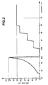
- the motivation for this particular choice of frequency will be better understood on reading the experimental curves of FIGS. 2 to 4 which will now be detailed and which have been obtained with a comb 1 designed to oscillate at around 3890 strokes / minute.
- the curve in Figure 2 represents the amplitude of the oscillations of this comb, as a function of the frequency of the power supply signal 7 of the motor 3, and this for a given value of the effective voltage of this signal. in evidence that for the frequencies higher than 70Hz, the amplitude of the oscillations of the comb 1 is almost constant, and is of the order of 30mm.
- the stator of the single-phase induction motor of such a swinging comb has always been supplied in the aforementioned frequency range, since it is known that in this particular range on the one hand the amplitude of the oscillations is stable and varies very little as a function of the supply frequency of the stator, and on the other hand that the comb oscillates at a fixed frequency, which is independent of the stator supply frequency and which is equal to what is called the natural frequency of the comb.
- FIG. 3 represents the effective intensity of the current consumed by the motor 3 as a function of the frequency of the supply signal 7. This curve makes it possible to note that in the vicinity of the particular frequency of 64.7 Hz, this intensity drops suddenly for reach around 4.4 A, while it was close to 8A in the frequency range usually recommended, that is to say for frequencies above 70Hz.
- FIG. 4 represents the frequency of oscillation of the shaft 2 of the comb as a function of the frequency of the supply signal 7. This curve shows that for frequencies greater than 65.9 Hz, the comb oscillates with a natural frequency of 64 , 7Hz, which corresponds to a comb oscillating very exactly at 3882 strokes / minute.
- the particular frequency of the power signal 7 for which the effective intensity of the current consumed by the single-phase induction motor is minimum ( Figure 3) and the amplitude of oscillations is maximum (Figure 2) therefore corresponds to the natural frequency of oscillation of the beating comb.
- FIG. 4 also makes it possible to highlight that unexpectedly, for frequencies between 62.6 Hz and 64.9 Hz, the oscillation of the comb is not asynchronous as one might have believed, but is on the contrary synchronous with the frequency of the power signal 7 of the stator of the single-phase induction motor.
- the comb is systematically self-starting. For frequencies of the power signal 7 between 64.9Hz and 65.9Hz, it is not possible to oscillate the comb. For frequencies higher than 65.9 Hz, it is necessary to force the comb to start, for example by manually communicating a torque to the shaft of the comb.
- the comb has the advantage of being self-starting, and of consuming a current of lower intensity.
- the concept of proximity to the natural frequency will be defined by the frequency range of the supply signal 7 of the stator of the single-phase induction motor in which the effective intensity of the current consumed by the motor is less than the effective intensity of the current consumed in the frequency range hitherto recommended.
- the vicinity of the natural frequency of the comb (64.7 Hz) will be constituted by the range of frequencies between 63.9 Hz and 64, 8Hz, that is to say in the frequency range [fO, 8Hz; f + O, 1Hz], where f represents the natural frequency of oscillation of the comb.
- This frequency range is not, however, limiting of the invention. It is in fact for the skilled person to determine for a given comb the exact range of frequencies around the natural frequency of oscillation of the comb in which the intensity of the current consumed by the induction motor. single phase fall.
- the frequency of the supply signal will be more particularly adjusted to the natural frequency of the comb with a tolerance of +/- 0.1 Hz.
- the amplitude of the oscillations is greater than that of the oscillations of the comb in its usual asynchronous operating range (frequencies above 70Hz) and the current consumed is lower. It is therefore possible to obtain oscillations of greater amplitude with a single-phase induction motor of lower electrical power.
- Adjusting this amplitude advantageously makes it possible to adapt the beating comb to any type of existing fibrous web, originating from the card on which the comb is mounted.
- the amplitude of the oscillations will be adjusted so as to obtain a sufficient engine torque, to minimize the number of jams of the comb, during operation.
- the drop in intensity of the current consumed by the single-phase induction motor in the narrow frequency range of the invention makes it possible to envisage the production of swinging combs having higher natural frequencies of oscillation, and thereby to increase the rate of work of the cards they equip.
- the intensity of the current consumed by the motor increases with the natural frequency of oscillation of the comb, and this whatever the frequency of supply of the stator. In the frequency range which has hitherto been recommended, it was limited, due to the excessively high current consumption, to the production of combs having a natural oscillation frequency of less than 4000 strokes / minute.
- stator supply frequency range it becomes possible to build combs oscillating at frequencies greater than 4000 strokes / minute, without risk of overheating the motor. single-phase induction.
- the electric power consumed by the motor is lower, it becomes possible to use single-phase induction motors of lower power, that is to say induction motors of lower dimension whose rotor has a lower inertia, which makes it possible to envisage the production of combs having a higher natural frequency of oscillation
- the electronic control system 4 comprises an electronic circuit 8, a microprocessor 9 and a speed controller 10 which delivers the power signal 7 from the stator of the single-phase induction motor.
- the microprocessor 9 manages in known manner a ROM 12 of EPROM type in which the program operating the microprocessor is stored, a random access memory 11, a keyboard 13 and a display 14.
- the frequency of the AC power signal 7 delivered by the variator 10 is fixed by the microprocessor 9 via the control signal 9 a .
- the swinging comb is further equipped with a sensor 5,6 which measures the amplitude of the oscillation of the shaft 2, and delivers to the electronic circuit 8 a variable voltage U whose instantaneous value is a function of the shaft rotation angle 2.
- this sensor was a hall effect magnetic sensor. It could also be a strain gauge mounted directly on the surface of the shaft 2, or any other sensor known to those skilled in the art and fulfilling the same function.
- the function of the electronic circuit 8 is to transform the variable voltage U delivered by the amplitude sensor 5,6 into a first analog signal 8 a characterizing the oscillation frequency of the shaft 2 and into a second digital signal 8 b of which the value is a function of the amplitude of the oscillations of the shaft 2.
- the electronic circuit 8 comprises at input a voltage / current converter constituted by resistance R, and a first RC filter formed by resistance R1 and capacitor C1.
- a first operational amplifier A1 mounted as a comparator receives as input a reference voltage Vref and the output signal of the above-mentioned first filter RC, and delivers for the microprocessor 9 the analog signal 8 a .
- the signal 8 a When the beating comb oscillates, the signal 8 a consists of a train of pulses whose frequency is directly a function of the actual oscillation frequency of the shaft 2.
- the output signal of the first RC filter is also amplified by means of a second operational amplifier A2 is filtered by a second RC filter constituted by the resistor R2 and the capacitor C2.
- the voltage across C2 corresponds to the average value of the variable voltage U delivered by the sensor 5,6, and is therefore proportional to the amplitude of the oscillations of the shaft 2.
- This voltage is converted by means of a converter analog / digital converter 15 which delivers the digital signal 8b aforementioned to the microprocessor 9.
- the microprocessor 9 is able, from the two signals 8 a and 8 b, to acquire at a given instant the value of the frequency and the amplitude of the oscillations of the shaft 2 of the beating comb.
- the operation of the microprocessor will now be detailed from the flow diagram of FIG. 6.
- the microprocessor 9 performs a scan loop of its keyboard 13 while waiting for input (step 16) by an operator with a minimum frequency (Fmin) and a maximum frequency (Fmax ). These two frequencies correspond to the lower and upper limits of a frequency range which is chosen to be wide enough to contain with certainty the natural frequency of oscillation of the comb. With regard to the comb, the operating curves of which have been given in FIGS. 2 to 4, for example, Fmin at 60 Hz and Fmax at 70 Hz will be fixed.
- the microprocessor 9 iteratively controls the variator 10 by the intermediary of the control signal 9 a such that this variator 10 delivers a supply signal 7 whose frequency will vary discontinuously, according to a predetermined frequency increment (dF) over the entire frequency range (Fmin, Fmax).
- This frequency increment (dF) can be set once and for all, or can optionally be entered at the same time as the limits of the frequency range (Fmin, Fmax).
- the microprocessor acquires and stores in random access memory 11 the frequency and the amplitude of the oscillations of the comb by means of signals 8 a and 8 b respectively . This operation of the microprocessor is illustrated by steps 17 to 22 of the flow diagram of FIG. 6.
- the RAM 11 contains a table of all the pairs of values (amplitude, frequency) acquired. From this table, the microprocessor determines the frequency F 0 corresponding to the maximum amplitude acquired (step 23), controls the variator 10 so that the latter delivers a supply signal 7 whose frequency is F 0 ( step 24), and displays this frequency on the display 14 for the operator (step 25).
- the frequency value F 0 which is calculated by the microprocessor corresponds to the natural frequency of the comb, with a tolerance which depends on the value of the frequency increment dF. More precisely, in the worst case, the value F 0 found will differ as much as possible from the real natural frequency of the comb by a value equal to 50% of dF. Consequently, to obtain a frequency F 0 which is equal to the natural frequency of the comb with a tolerance of +/- 0.1 Hz, the frequency increment dF will have to be at most 0.2 Hz.
- this is designed to automatically determine the natural oscillation frequency of the beating comb, no longer from a measurement of the oscillation amplitude of the comb, but from a measurement of the effective intensity of the current consumed by the single-phase induction motor 3.
- This variant embodiment will not be described in detail because it is easily deduced for those skilled in the art from the variant which has been described with reference to FIGS. 5 and 6. It suffices to replace the sensor 5,6 which measures the amplitude of the oscillations with a sensor measuring the effective intensity of the supply signal 7, and modifying step 23 of the flow diagram of FIG. 6, by calculating the frequency F 0 corresponding to the minimum intensity acquired, and no longer to the amplitude maximum oscillation.
- step 21 of systematic storage of the pairs of values acquired by the microprocessor in step 20, it that is to say a frequency associated either with an amplitude or with an intensity according to the variant embodiment of the electronic control system.
- this step 21 will be replaced by a step of storing the amplitude (respectively of the intensity) acquired at a given instant, provided that this amplitude (respectively intensity) is greater (respectively less) than an amplitude ( intensity respectively) previously acquired and stored.
- the invention is also not limited to the production of swing combs for a textile machine, but can more generally be applied to any oscillating mechanical device whose oscillations are maintained by means of a single-phase induction motor.
Landscapes
- Engineering & Computer Science (AREA)
- Textile Engineering (AREA)
- Preliminary Treatment Of Fibers (AREA)
- Apparatuses For Generation Of Mechanical Vibrations (AREA)
- Control Of Ac Motors In General (AREA)
- Treatment Of Fiber Materials (AREA)
- Yarns And Mechanical Finishing Of Yarns Or Ropes (AREA)
- Control Of Multiple Motors (AREA)
Applications Claiming Priority (2)
| Application Number | Priority Date | Filing Date | Title |
|---|---|---|---|
| FR9511629 | 1995-09-28 | ||
| FR9511629A FR2739398B1 (fr) | 1995-09-28 | 1995-09-28 | Dispositif mecanique oscillant perfectionne, notamment peigne battant de machine textile, dont les oscillations sont entretenues au moyen d'un moteur a induction monophase |
Publications (2)
| Publication Number | Publication Date |
|---|---|
| EP0765955A1 true EP0765955A1 (de) | 1997-04-02 |
| EP0765955B1 EP0765955B1 (de) | 1998-09-02 |
Family
ID=9483197
Family Applications (1)
| Application Number | Title | Priority Date | Filing Date |
|---|---|---|---|
| EP96490036A Expired - Lifetime EP0765955B1 (de) | 1995-09-28 | 1996-09-25 | Mechanische Schwingvorrichtung, insbesondere Textilmaschinenhackerkamm dessen Schwingungen mittels eines monofasen Induktionsmotors instandgesetzt sind |
Country Status (7)
| Country | Link |
|---|---|
| US (1) | US5872440A (de) |
| EP (1) | EP0765955B1 (de) |
| JP (1) | JPH09170118A (de) |
| AT (1) | ATE170573T1 (de) |
| DE (1) | DE69600589T2 (de) |
| DK (1) | DK0765955T3 (de) |
| FR (1) | FR2739398B1 (de) |
Families Citing this family (5)
| Publication number | Priority date | Publication date | Assignee | Title |
|---|---|---|---|---|
| FI112298B (fi) * | 1996-12-19 | 2003-11-14 | Kone Corp | Menetelmä ja laitteisto moottorin värähtelyjen vaimentamiseksi |
| DE10149525A1 (de) * | 2000-10-26 | 2002-05-02 | Heidelberger Druckmasch Ag | Verfahren zur Kompensation mechanischer Schwingungen in Maschinen |
| US9719888B2 (en) * | 2012-10-09 | 2017-08-01 | Quantitative Engineering Solutions, LLC | Cotton acquisition and tracking system |
| CH719416A1 (de) | 2022-02-11 | 2023-08-31 | Rieter Ag Maschf | Karde mit einem Beschleunigungssensor zur Messung von Körperschall. |
| CH719417A1 (de) * | 2022-02-11 | 2023-08-31 | Rieter Ag Maschf | Karde mit einem Beschleunigungssensor zur Messung von Körperschall. |
Citations (4)
| Publication number | Priority date | Publication date | Assignee | Title |
|---|---|---|---|---|
| DE1685603A1 (de) * | 1967-10-28 | 1971-08-19 | Schubert & Salzer Maschinen | Hackerantrieb |
| EP0519878A1 (de) * | 1991-06-18 | 1992-12-23 | MONTENERO O.M.T.P. OFFICINA MECCANICA di Finocchi Paolo & C.SNC | Kartenflorkammantriebssystem in Maschinen für die Textilindustrie |
| US5345160A (en) * | 1993-06-02 | 1994-09-06 | Henri Corniere | Variable frequency control system for single phase induction motors |
| US5422557A (en) * | 1992-10-22 | 1995-06-06 | Samsung Electronics Co., Ltd. | Method and apparatus for controlling the speed of a single phase induction motor using frequency variation |
Family Cites Families (9)
| Publication number | Priority date | Publication date | Assignee | Title |
|---|---|---|---|---|
| US3750235A (en) * | 1971-08-04 | 1973-08-07 | Fiber Controls Corp | Textile processing equipment |
| CH601093A5 (de) * | 1976-11-05 | 1978-06-30 | Zellweger Uster Ag | |
| US4181877A (en) * | 1976-11-22 | 1980-01-01 | Westinghouse Electric Corp. | Inertia compensated static motor drive |
| JPS5396423A (en) * | 1977-02-01 | 1978-08-23 | Mitsubishi Electric Corp | Control system for induction motor |
| FR2451658A1 (fr) * | 1979-03-16 | 1980-10-10 | Asa Sa | Installation perfectionnee pour la commande des variations de vitesse des boites a cames de machines textiles |
| US4249120A (en) * | 1979-07-26 | 1981-02-03 | Mcgraw-Edison Co. | Variable speed induction motor control system |
| US5111374A (en) * | 1990-06-22 | 1992-05-05 | The University Of Tennessee Research Corp. | High frequency quasi-resonant DC voltage notching scheme of a PWM voltage fed inverter for AC motor drives |
| US5168202A (en) * | 1991-08-30 | 1992-12-01 | Platt Saco Lowell Corporation | Microprocessor control of electric motors |
| EP0612933B1 (de) * | 1993-02-24 | 1998-05-06 | Shinko Electric Co. Ltd. | Schwingungskontrollanlage für rotierende Maschinen |
-
1995
- 1995-09-28 FR FR9511629A patent/FR2739398B1/fr not_active Expired - Fee Related
-
1996
- 1996-09-25 EP EP96490036A patent/EP0765955B1/de not_active Expired - Lifetime
- 1996-09-25 DE DE69600589T patent/DE69600589T2/de not_active Expired - Lifetime
- 1996-09-25 DK DK96490036T patent/DK0765955T3/da active
- 1996-09-25 AT AT96490036T patent/ATE170573T1/de not_active IP Right Cessation
- 1996-09-26 US US08/721,107 patent/US5872440A/en not_active Expired - Lifetime
- 1996-09-30 JP JP8279978A patent/JPH09170118A/ja active Pending
Patent Citations (4)
| Publication number | Priority date | Publication date | Assignee | Title |
|---|---|---|---|---|
| DE1685603A1 (de) * | 1967-10-28 | 1971-08-19 | Schubert & Salzer Maschinen | Hackerantrieb |
| EP0519878A1 (de) * | 1991-06-18 | 1992-12-23 | MONTENERO O.M.T.P. OFFICINA MECCANICA di Finocchi Paolo & C.SNC | Kartenflorkammantriebssystem in Maschinen für die Textilindustrie |
| US5422557A (en) * | 1992-10-22 | 1995-06-06 | Samsung Electronics Co., Ltd. | Method and apparatus for controlling the speed of a single phase induction motor using frequency variation |
| US5345160A (en) * | 1993-06-02 | 1994-09-06 | Henri Corniere | Variable frequency control system for single phase induction motors |
Also Published As
| Publication number | Publication date |
|---|---|
| DE69600589D1 (de) | 1998-10-08 |
| JPH09170118A (ja) | 1997-06-30 |
| DK0765955T3 (da) | 1998-11-16 |
| DE69600589T2 (de) | 1999-01-28 |
| FR2739398B1 (fr) | 1997-12-19 |
| US5872440A (en) | 1999-02-16 |
| FR2739398A1 (fr) | 1997-04-04 |
| ATE170573T1 (de) | 1998-09-15 |
| EP0765955B1 (de) | 1998-09-02 |
Similar Documents
| Publication | Publication Date | Title |
|---|---|---|
| CH630586A5 (fr) | Appareil pour bobiner un fil. | |
| EP2789976B1 (de) | Elektronischer Antriebsschaltkreis einer Vorrichtung mit Resonator vom Typ MEMS, und Verfahren zu seiner Ingangsetzung | |
| EP0765955B1 (de) | Mechanische Schwingvorrichtung, insbesondere Textilmaschinenhackerkamm dessen Schwingungen mittels eines monofasen Induktionsmotors instandgesetzt sind | |
| FR2586883A1 (fr) | Procede et dispositif d'alimentation electrique d'un transducteur generateur de vibrations tant sonores qu'ultrasonores. | |
| EP0168311B1 (de) | Schleifmaschine mit einem Regelkreis zum Positionieren des Werkzeugschlittens | |
| FR2615213A1 (fr) | Perfectionnements aux machines de teinture | |
| FR2511767A1 (fr) | Appareil magnetique a induction pour la mesure d'un debit d'ecoulement d'un liquide | |
| EP0014164B1 (de) | Viskosimeter und Viskosistat | |
| FR2617433A1 (fr) | Dispositif de commande d'une rangee de marteaux et procede d'alimentation en courant d'un moteur | |
| FR2653060A1 (fr) | Installation pour regler la tension de la nappe dans une rotative. | |
| FR2656436A1 (fr) | Procede de traitement par vibration des pieces et dispositif pour la mise en óoeuvre de ce procede. | |
| EP0802403B1 (de) | Vorrichtung zur Messung eines Motordrehmomentes | |
| EP0023164B1 (de) | Vorrichtung, um die Nadel eines Schwingungsviskosimeters in Schwingungen zu versetzen | |
| EP0468862B1 (de) | Regelverfahren für die Rotationsgeschwindigkeit der Trommel einer Zentrifugiermaschine als Funktion der Unwucht und Maschine zur Verwendung dieses Verfahrens | |
| CH642404A5 (fr) | Installation de regulation de la section de la meche de fibres sortant d'une machine d'etirage. | |
| CH657553A5 (en) | Method and device for determining the deflection of an electrical-discharge cutting wire | |
| EP2044680A2 (de) | Verfahren und vorrichtung zur steuerung der drehzahl des rotors eines piezoelektrischen motors | |
| FR2580442A1 (fr) | Dispositif de regulation d'un moteur electrique a courant continu et applications a un mesureur d'effort et a un dispositif d'exercice physique | |
| EP1637723A1 (de) | System zur Versorgung die Brennkraftmaschine eines Kraftfahrzeuges mit Kraftstoff und Kraftstoffdruckregelverfahren für eine solche Brennkraftmaschine | |
| CH302598A (fr) | Procédé de mesure continue d'une grandeur variable et dispositif pour sa mise en oeuvre. | |
| FR2607651A1 (fr) | Dispositif d'alimentation d'un generateur d'ultrasons, en particulier pour un appareil de detartrage des dents | |
| FR2568693A1 (fr) | Dispositif d'entrainement d'un miroir dans un mouvement alternatif | |
| FR2607156A1 (fr) | Dispositif de securite pour machine a tricoter rectiligne | |
| CH721335A2 (fr) | Procédé et système de mesure d'un paramètre de fonctionnement d'un oscillateur pour montre mécanique | |
| CH288775A (fr) | Procédé et dispositif de contrôle d'un niveau liquide. |
Legal Events
| Date | Code | Title | Description |
|---|---|---|---|
| PUAI | Public reference made under article 153(3) epc to a published international application that has entered the european phase |
Free format text: ORIGINAL CODE: 0009012 |
|
| AK | Designated contracting states |
Kind code of ref document: A1 Designated state(s): AT BE CH DE DK GB IT LI |
|
| 17P | Request for examination filed |
Effective date: 19970920 |
|
| GRAG | Despatch of communication of intention to grant |
Free format text: ORIGINAL CODE: EPIDOS AGRA |
|
| RAP1 | Party data changed (applicant data changed or rights of an application transferred) |
Owner name: THIBEAU |
|
| 17Q | First examination report despatched |
Effective date: 19971126 |
|
| GRAG | Despatch of communication of intention to grant |
Free format text: ORIGINAL CODE: EPIDOS AGRA |
|
| GRAH | Despatch of communication of intention to grant a patent |
Free format text: ORIGINAL CODE: EPIDOS IGRA |
|
| GRAH | Despatch of communication of intention to grant a patent |
Free format text: ORIGINAL CODE: EPIDOS IGRA |
|
| GRAA | (expected) grant |
Free format text: ORIGINAL CODE: 0009210 |
|
| AK | Designated contracting states |
Kind code of ref document: B1 Designated state(s): AT BE CH DE DK GB IT LI |
|
| REF | Corresponds to: |
Ref document number: 170573 Country of ref document: AT Date of ref document: 19980915 Kind code of ref document: T |
|
| ITF | It: translation for a ep patent filed | ||
| REG | Reference to a national code |
Ref country code: CH Ref legal event code: NV Representative=s name: BOVARD AG PATENTANWAELTE Ref country code: CH Ref legal event code: EP |
|
| GBT | Gb: translation of ep patent filed (gb section 77(6)(a)/1977) |
Effective date: 19980903 |
|
| REF | Corresponds to: |
Ref document number: 69600589 Country of ref document: DE Date of ref document: 19981008 |
|
| REG | Reference to a national code |
Ref country code: DK Ref legal event code: T3 |
|
| PLBE | No opposition filed within time limit |
Free format text: ORIGINAL CODE: 0009261 |
|
| STAA | Information on the status of an ep patent application or granted ep patent |
Free format text: STATUS: NO OPPOSITION FILED WITHIN TIME LIMIT |
|
| 26N | No opposition filed | ||
| REG | Reference to a national code |
Ref country code: GB Ref legal event code: IF02 |
|
| PGFP | Annual fee paid to national office [announced via postgrant information from national office to epo] |
Ref country code: AT Payment date: 20020820 Year of fee payment: 7 |
|
| PGFP | Annual fee paid to national office [announced via postgrant information from national office to epo] |
Ref country code: DK Payment date: 20020821 Year of fee payment: 7 |
|
| PGFP | Annual fee paid to national office [announced via postgrant information from national office to epo] |
Ref country code: CH Payment date: 20020911 Year of fee payment: 7 |
|
| PGFP | Annual fee paid to national office [announced via postgrant information from national office to epo] |
Ref country code: GB Payment date: 20020917 Year of fee payment: 7 |
|
| PG25 | Lapsed in a contracting state [announced via postgrant information from national office to epo] |
Ref country code: GB Free format text: LAPSE BECAUSE OF NON-PAYMENT OF DUE FEES Effective date: 20030925 Ref country code: AT Free format text: LAPSE BECAUSE OF NON-PAYMENT OF DUE FEES Effective date: 20030925 |
|
| PG25 | Lapsed in a contracting state [announced via postgrant information from national office to epo] |
Ref country code: LI Free format text: LAPSE BECAUSE OF NON-PAYMENT OF DUE FEES Effective date: 20030930 Ref country code: DK Free format text: LAPSE BECAUSE OF NON-PAYMENT OF DUE FEES Effective date: 20030930 Ref country code: CH Free format text: LAPSE BECAUSE OF NON-PAYMENT OF DUE FEES Effective date: 20030930 |
|
| REG | Reference to a national code |
Ref country code: DK Ref legal event code: EBP |
|
| GBPC | Gb: european patent ceased through non-payment of renewal fee |
Effective date: 20030925 |
|
| REG | Reference to a national code |
Ref country code: CH Ref legal event code: PL |
|
| PGFP | Annual fee paid to national office [announced via postgrant information from national office to epo] |
Ref country code: DE Payment date: 20100910 Year of fee payment: 15 |
|
| PGFP | Annual fee paid to national office [announced via postgrant information from national office to epo] |
Ref country code: IT Payment date: 20110926 Year of fee payment: 16 |
|
| PGFP | Annual fee paid to national office [announced via postgrant information from national office to epo] |
Ref country code: BE Payment date: 20110923 Year of fee payment: 16 |
|
| BERE | Be: lapsed |
Owner name: *THIBEAU Effective date: 20120930 |
|
| REG | Reference to a national code |
Ref country code: DE Ref legal event code: R119 Ref document number: 69600589 Country of ref document: DE Effective date: 20130403 |
|
| PG25 | Lapsed in a contracting state [announced via postgrant information from national office to epo] |
Ref country code: BE Free format text: LAPSE BECAUSE OF NON-PAYMENT OF DUE FEES Effective date: 20120930 Ref country code: DE Free format text: LAPSE BECAUSE OF NON-PAYMENT OF DUE FEES Effective date: 20130403 |
|
| PG25 | Lapsed in a contracting state [announced via postgrant information from national office to epo] |
Ref country code: IT Free format text: LAPSE BECAUSE OF NON-PAYMENT OF DUE FEES Effective date: 20120925 |